Design
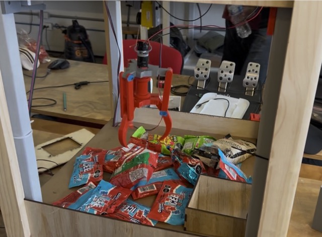
Claw Machine
A type of arcade vending game where players use a joystick to control a mechanical claw, attempting to grab prizes.
Design Process
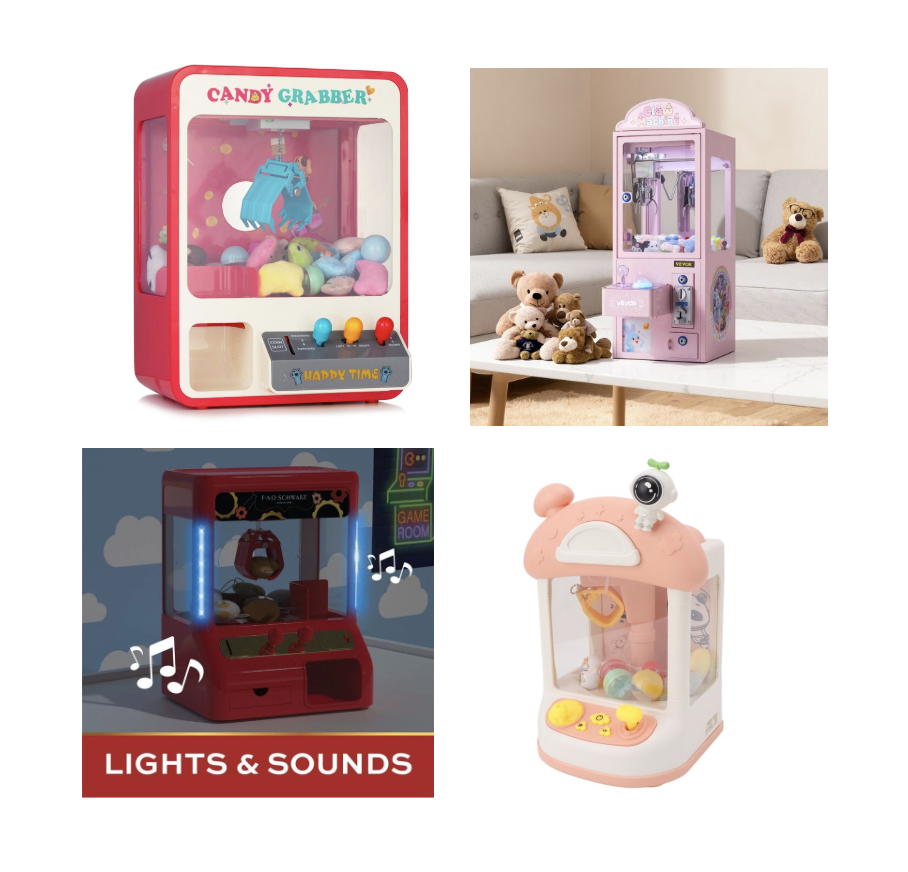
To begin designing the machine, I first created a moodboard to define the visual direction I wanted for the project. At the same time, I established the main design requirements for the machine:
- Modularity
- Avoiding the use of glue
- Organic aesthetic
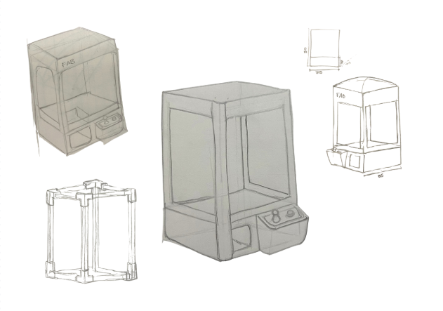
After that, I started sketching different ideas for the claw machine.
Material Selection
The most challenging part was finding a complete solution that met all my requirements, especially because I did not want the screws to be visible. At first, I considered three possible materials for the enclosure:
- 3D printing
- Wood
- Metal
After analysing the different options, I decided to build it out of wood. This choice allowed me to complete the 3D model in SolidWorks. Once I had figured out how to make almost all the parts, I started assembling the box.
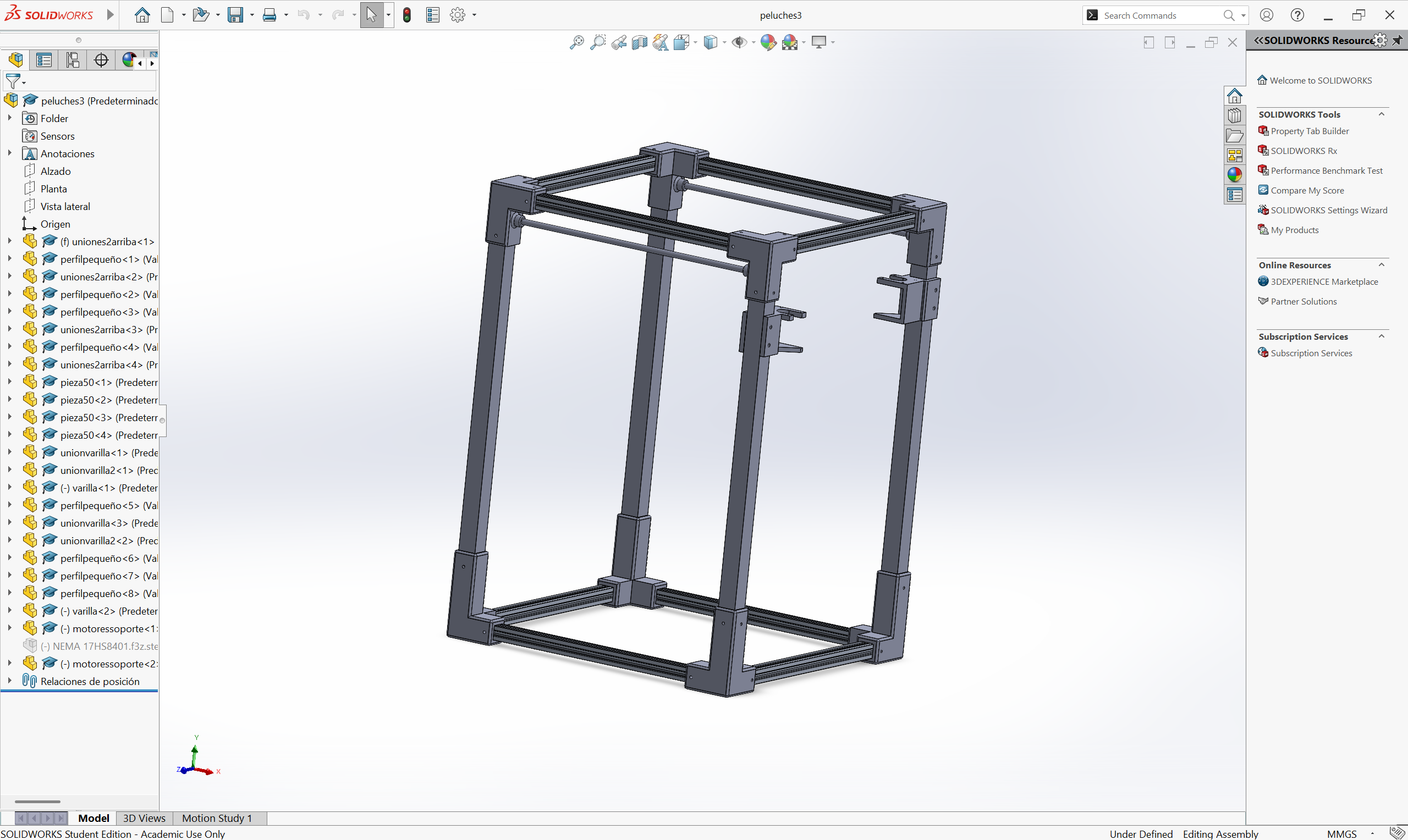
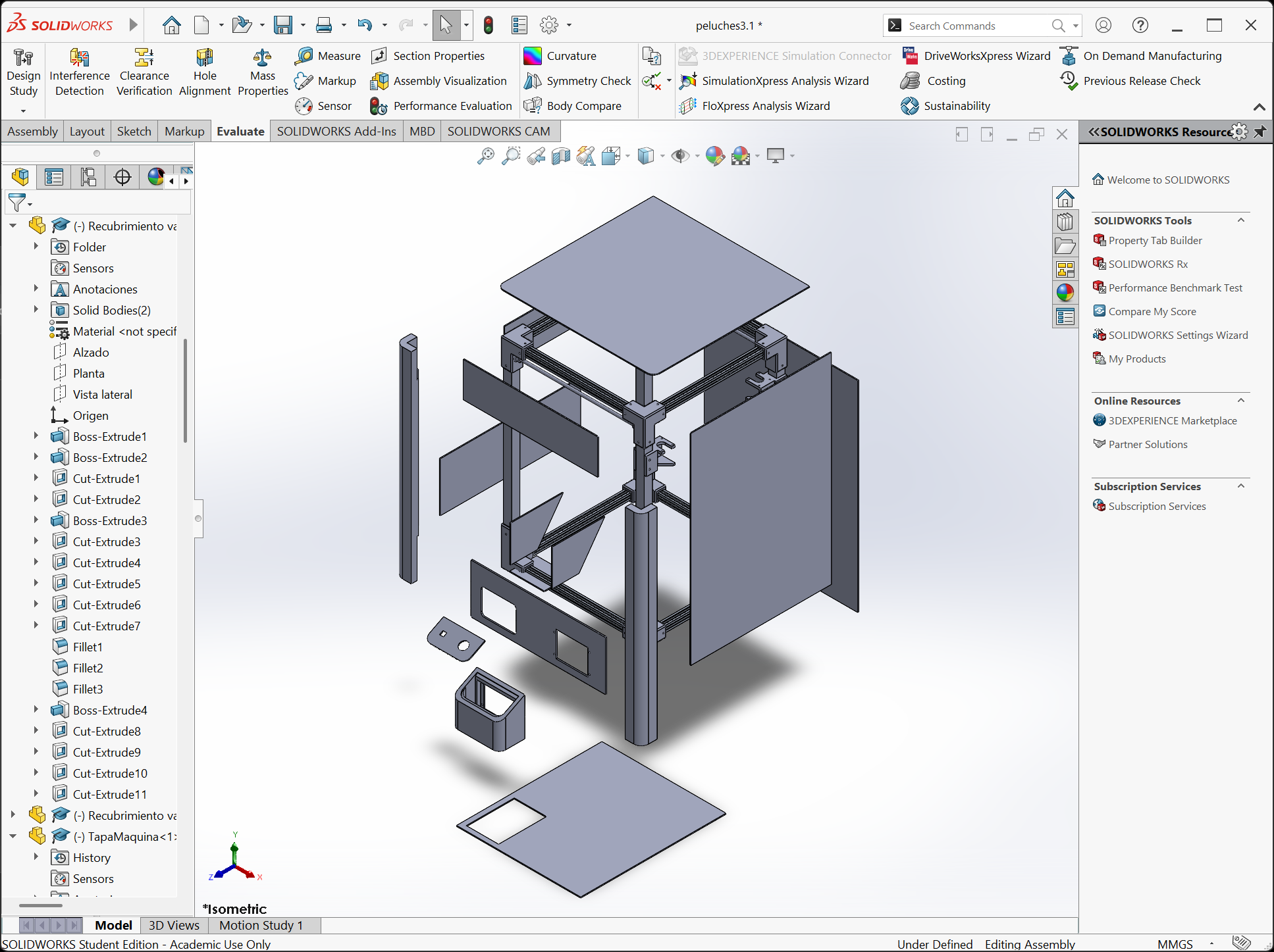
3D Model — SolidWorks
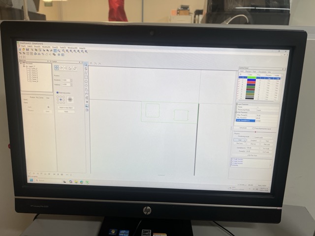
SolidWorks
I normally use SolidWorks to plan and test how I want to build a product. It provides me with the measurements and parts that I need.
SOFTWARE & TOOLS
- SolidWorks — 3D parametric modelling
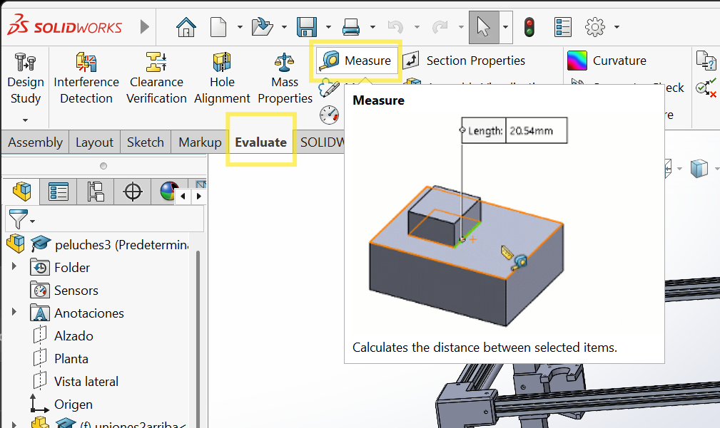
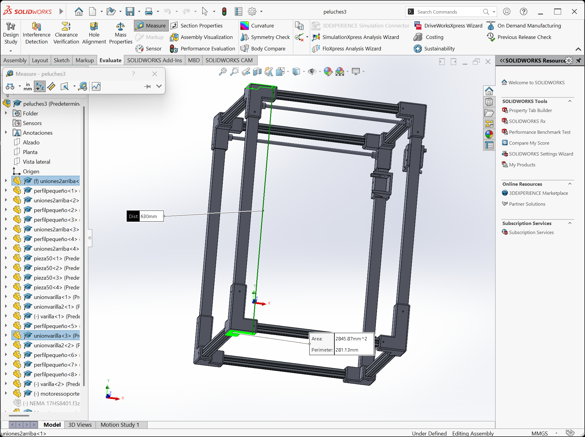
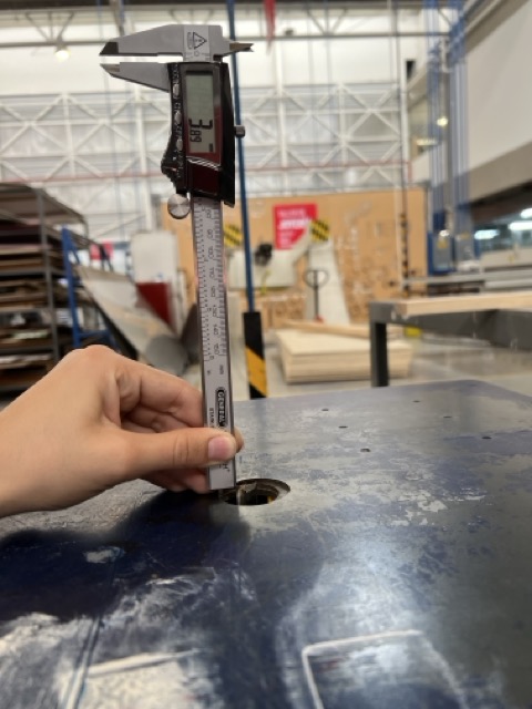
- Measure — dimension extraction from the team assembly
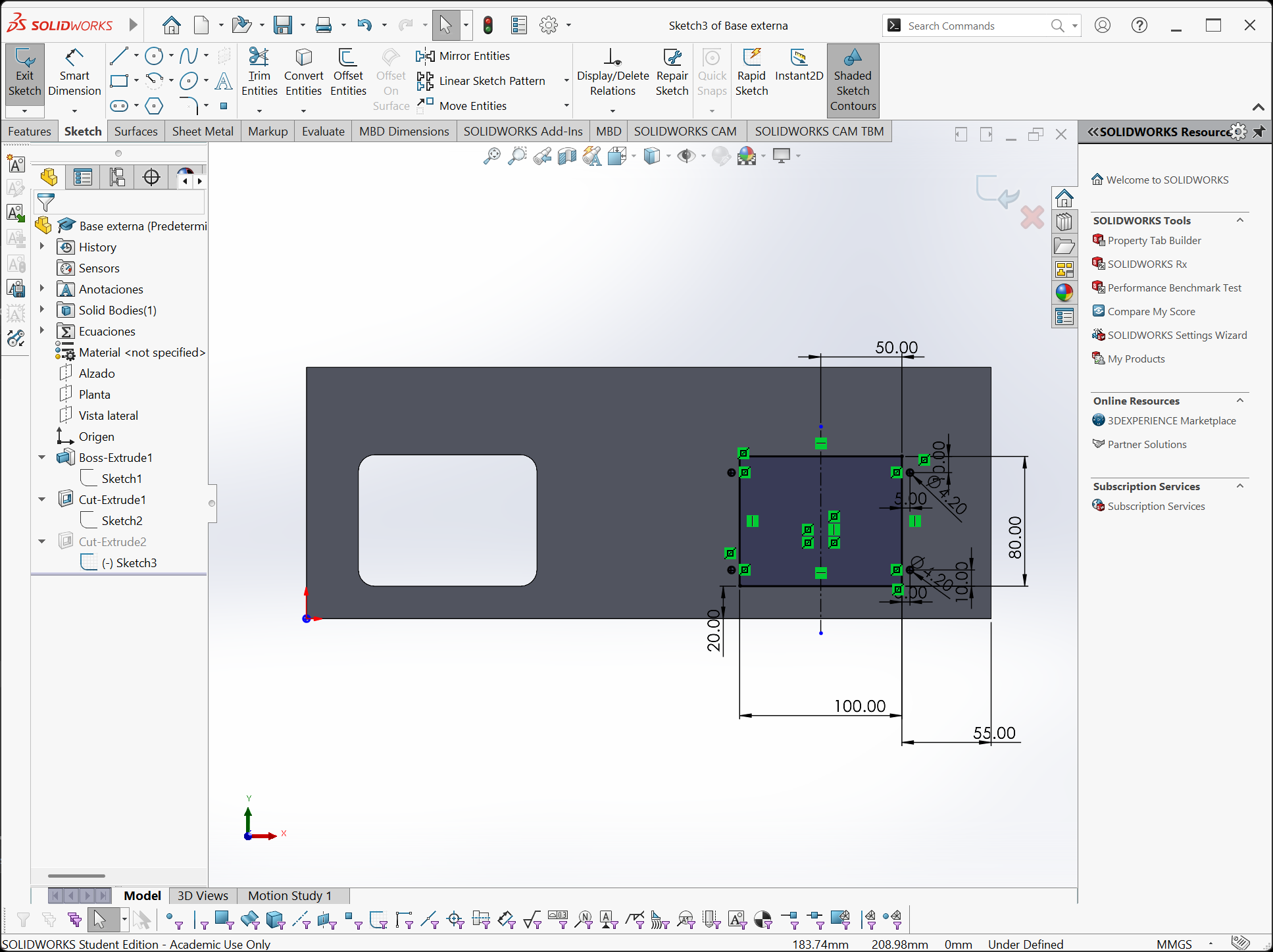
- Extrude Boss / Cut — building and hollowing solids
- Fillet — adding organic rounded edges
- Assembly — checking fit between all pieces
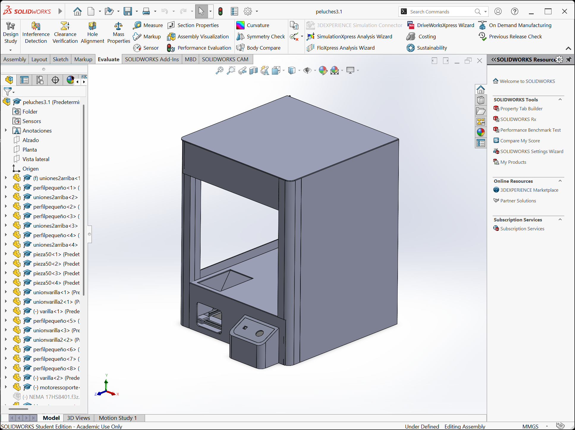
DESIGN WORKFLOW
- 01 Open team assembly → extract dimensions with Measure tool.
- 02 Model each structural piece individually based on sketches.
- 03 Build a sub-assembly to check that pieces fit together.
- 04 Iterate — adjust measurements until joints are correct.
Here you can find the general process of how I made the 3D model. I used the same tools I learned in the 3D modeling week, check the page if you want a more detailed explanation of how to build in SolidWorks.
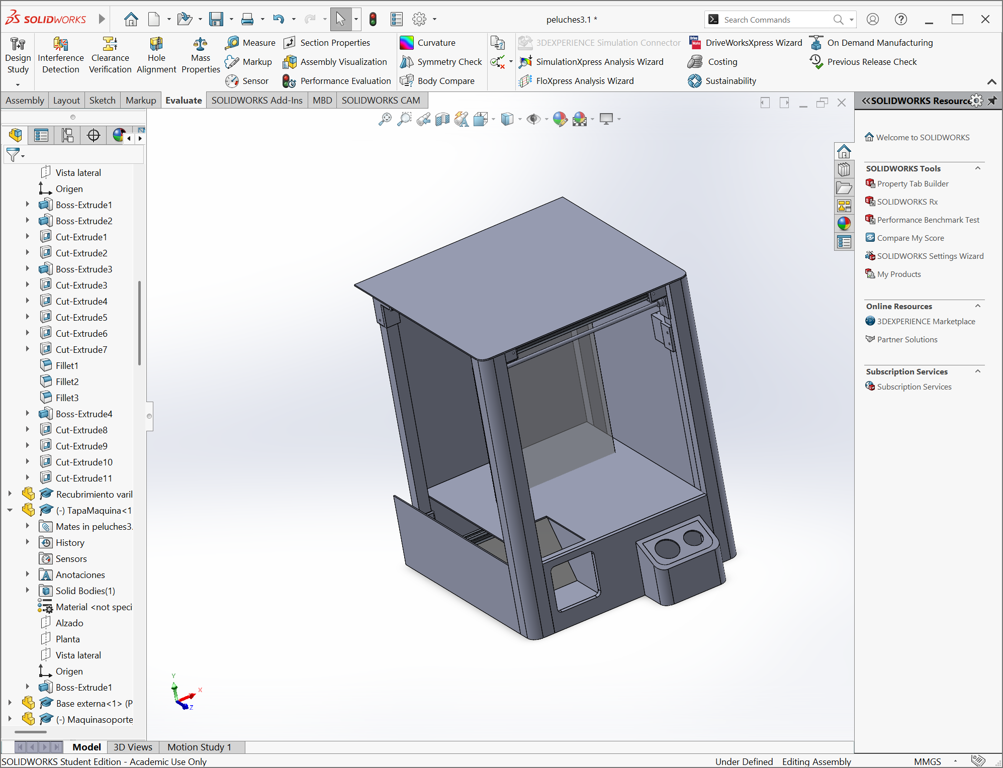
Problem
At first I designed a machine that was supposed to have a disposing structure under the metal structure, but then my team sent me the 3D model of the machine and I had to change some things.
Structure Fabrication
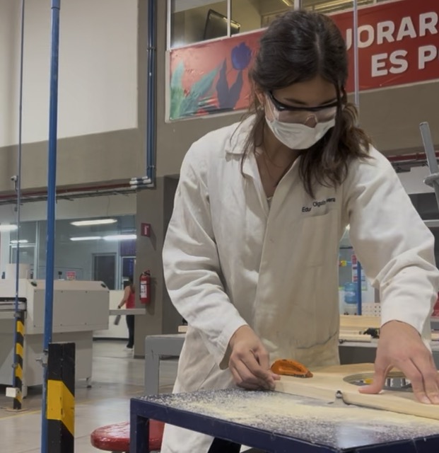
Safety Measures
If you work with machines it is important to wear the correct equipment: overalls, safety boots, safety glasses and preferably a face mask (otherwise you could end up with a sore throat like I did). Also make sure to pay full attention when using the machines to prevent accidents.
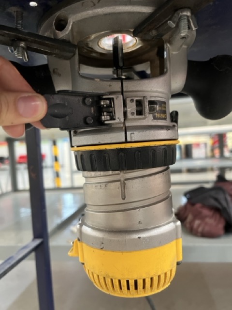
MACHINES USED
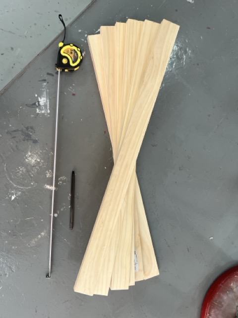
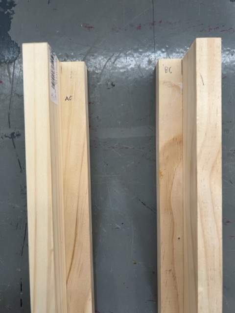
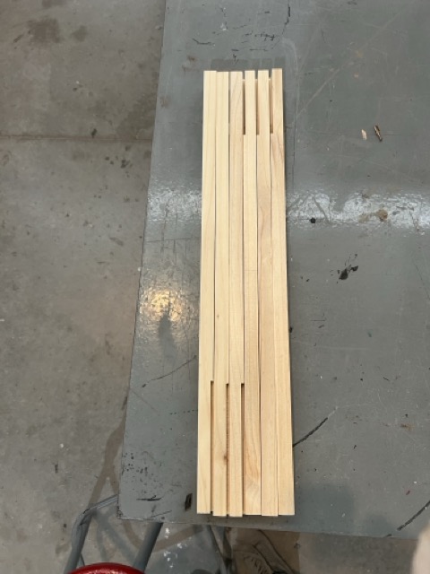
- Miter Saw — crosscut pine boards to length
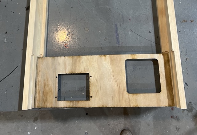
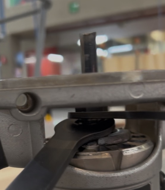
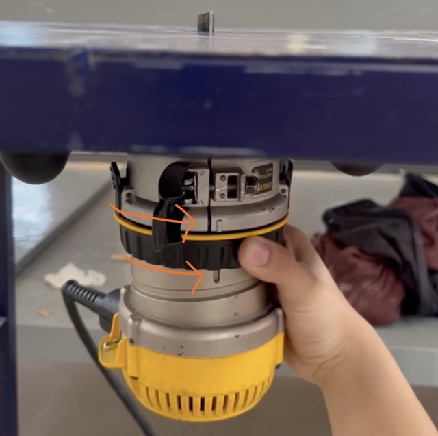
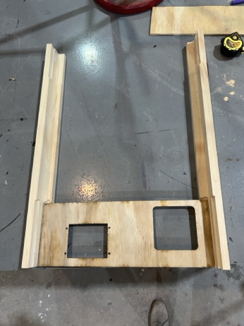
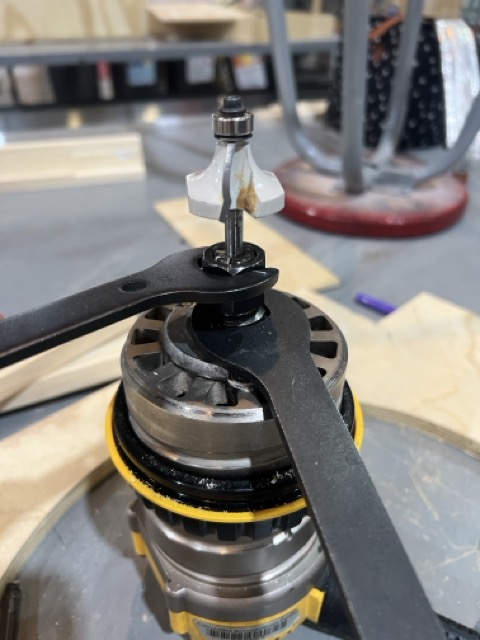
- Router Table — mill grooves for panel insertion
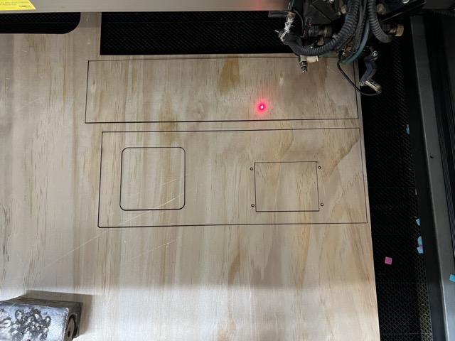
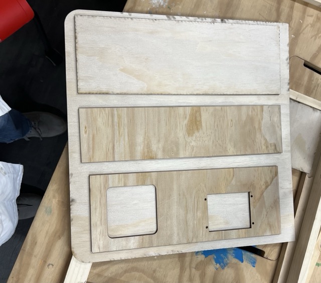
- Laser Cutter — cut 4 mm plywood front panels
- Band Saw — cut brackets and extension pieces
- Dremel — trim metal corner brackets to size
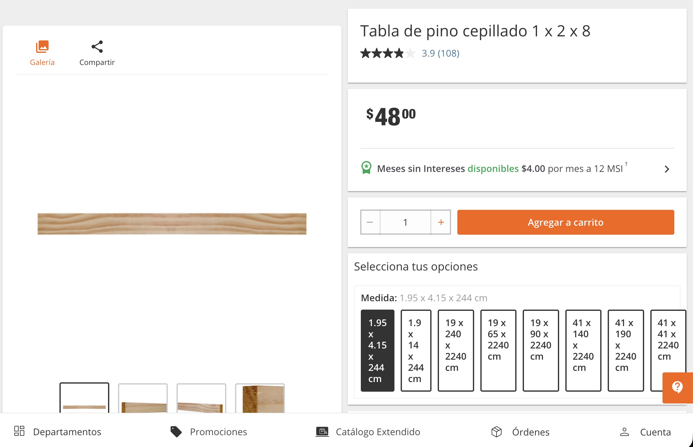
MATERIALS
- Pine wood boards — 1.22 m × 2 (main frame)
- 4 mm plywood (triplay) — front panels
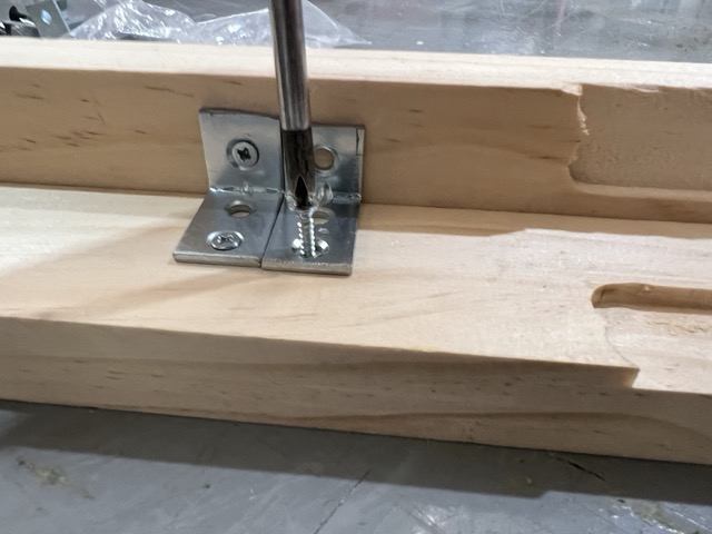
- Metal corner brackets — structural joints
- Flat-head wood screws
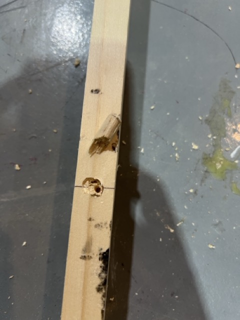
- Wooden dowels (first joint attempt)
- Clear acetate sheet — front window panel
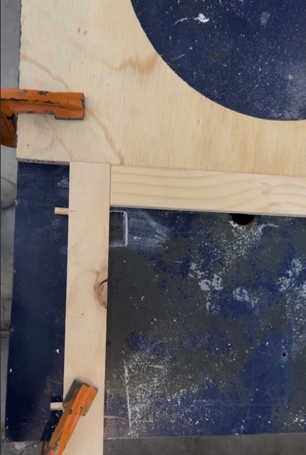
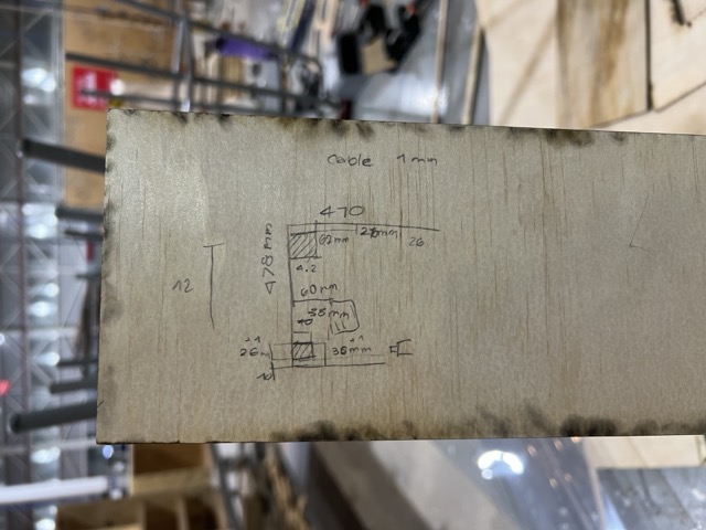
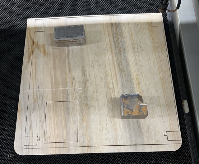
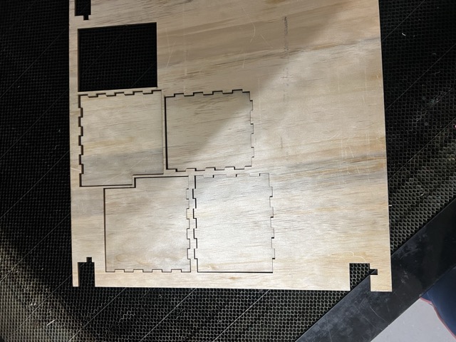
Below are the detailed steps I followed to fabricate the structure. The process combined miter cutting, router milling, laser cutting, and wood joinery into one integrated workflow.
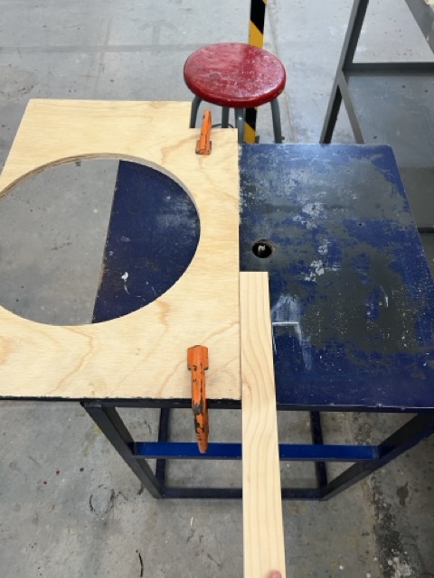
General Recommendation
Try testing your project on scrap pieces first to avoid wasting material.
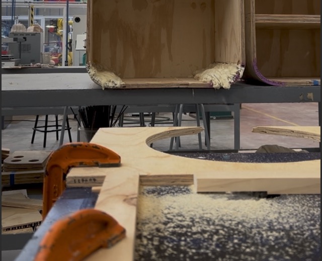
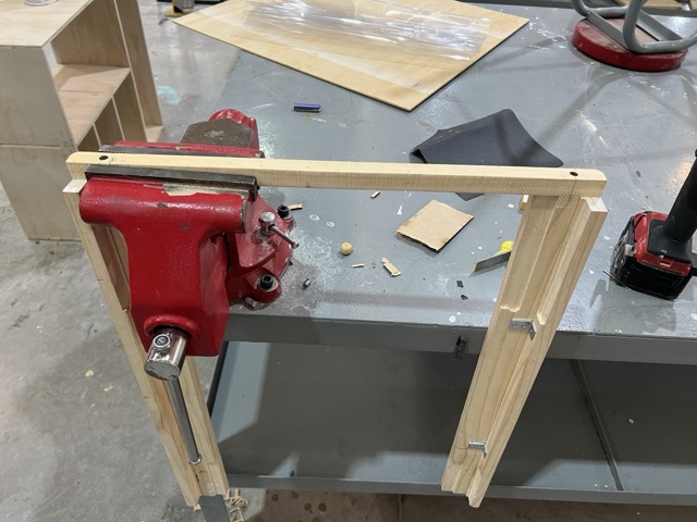
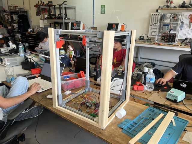
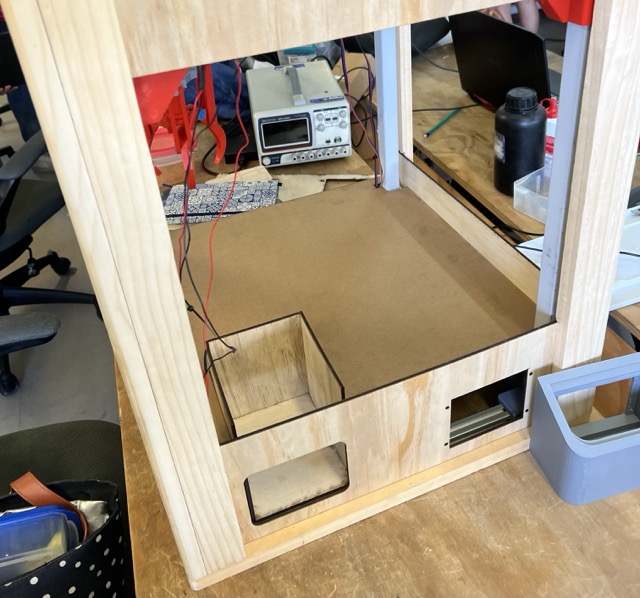
Problem
Since we had limited time to build the machine, I based the box design on the measurements my team sent me. However, when I finished and compared it to the machine's frame, I realized the frame was slightly taller, which meant my box didn't fit.
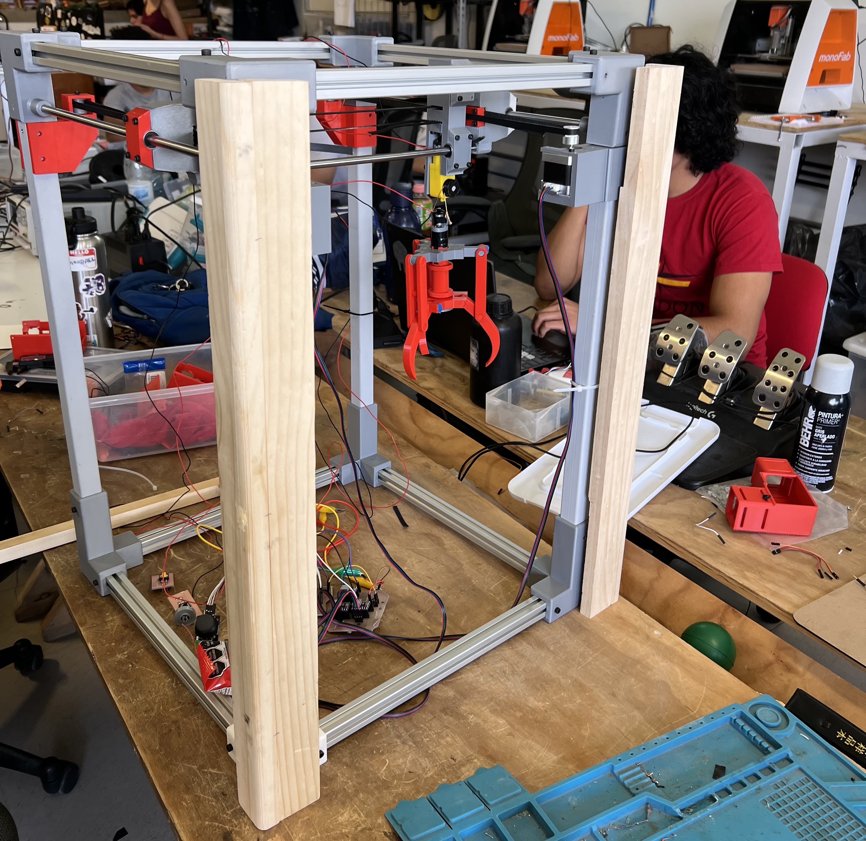
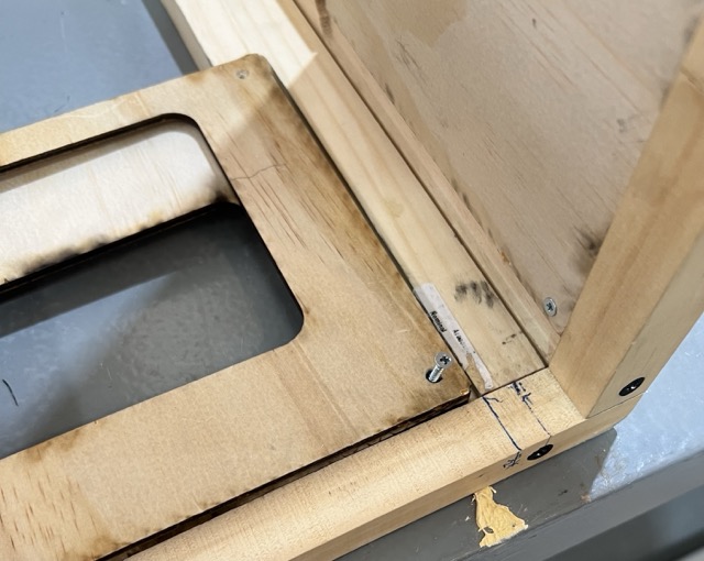
Solution
I used a spare board, cutting two pieces to the width and length of the machine. I cut these in half with a band saw and screwed them to the underside of the machine. In the end, the problem had a silver lining: it gave the structure more stability.
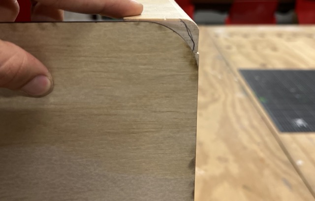
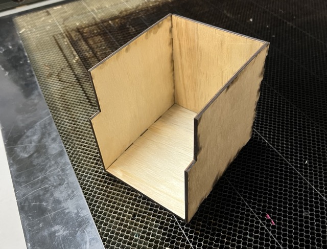
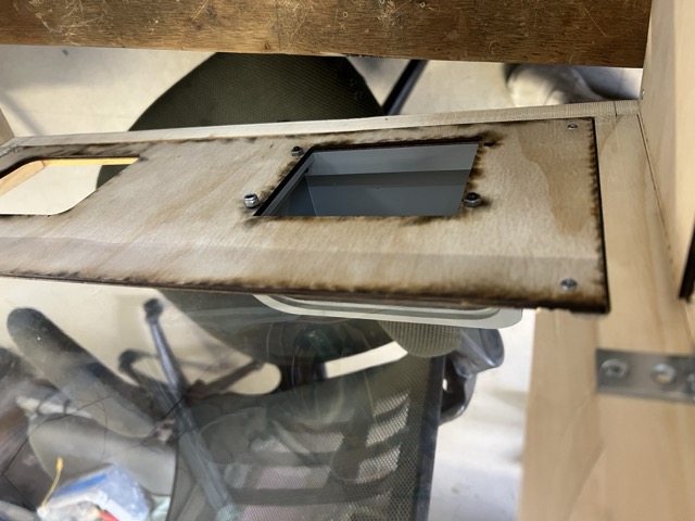
Details
After I had the structure pieces, I started working on the final details. First I had to solve some problems, here is the process:
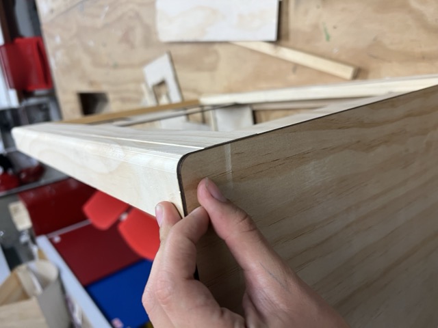
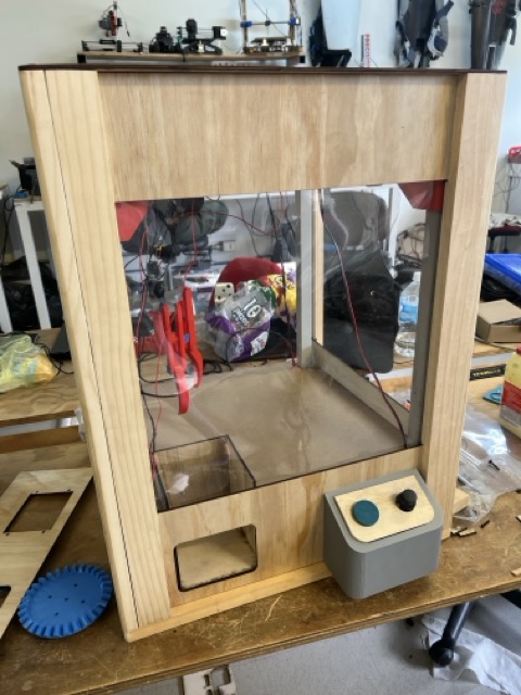
Final Result
At the end I really liked how it turned out.