12. Group Machine Design
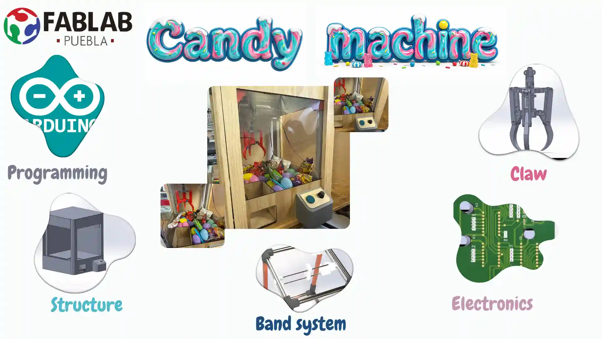
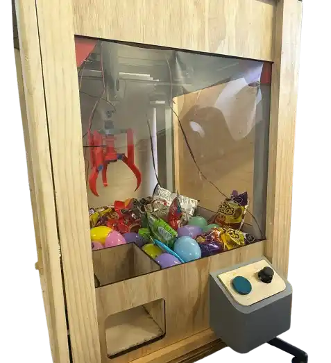
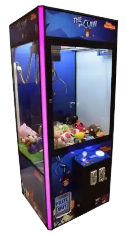
Our idea was to make a machine that has a claw for candy, taking inspiration from those found in shopping malls.
Individual Contributions
The team was organized with the following roles to ensure a successful build:
- Danna Paola García Sánchez: Structural Design & Electronics.
- Antonio Martínez Martínez: Movement mechanism design.
- Rafael Lee Romero: Claw design.
- Carlos Gutiérrez Martínez: Structural assembly.
- Nicole Friederichs Espinosa: Exterior structure design and fabrication.
Mechanical Materials
| Quantity | Component | Value / Model | Description |
|---|---|---|---|
8 | Aluminum Profile | 20x20x300 mm | Main horizontal frame structure. |
4 | Metal bar | 26x26x500 mm | Vertical gantry support. |
4 | Linear Bearings | LM8UU | Linear motion guide for the axes. |
25 | Screws | M3 | General assembly for 3D printed parts. |
25 | Screws | M4 | Profile mounting and motor support. |
Electronic Components
This is the list of electronic components used for the control board and the motion system of the candy claw machine:
| Quantity | Component | Value / Model | Description |
|---|---|---|---|
1 | Microcontroller | Pi Pico 2 | Main logic and motor control. |
3 | Motor Driver | DRV8825 | Stepper driver for X and Y axes. |
1 | Voltage Regulator | AMS1117-3.3V | 3.3V logic supply. |
3 | Stepper Motor | NEMA 17 | High-torque axis drive. |
1 | DC Gearmotor | TT Motor (Yellow) | Basic plastic gearmotor for robotics. |
1 | Micro Gearmotor | Pololu Style | Compact metal gearmotor for precise control. |
With these components, we ensure stable control and enough power to handle the mechanical movements of the machine.
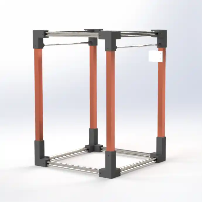
The first thing that was carried out was the basic structure with the joints and the 20 mm profiles and the 26 mm bars. This taking into account that in Fab Lab Puebla we have 20 mm aluminum profiles.
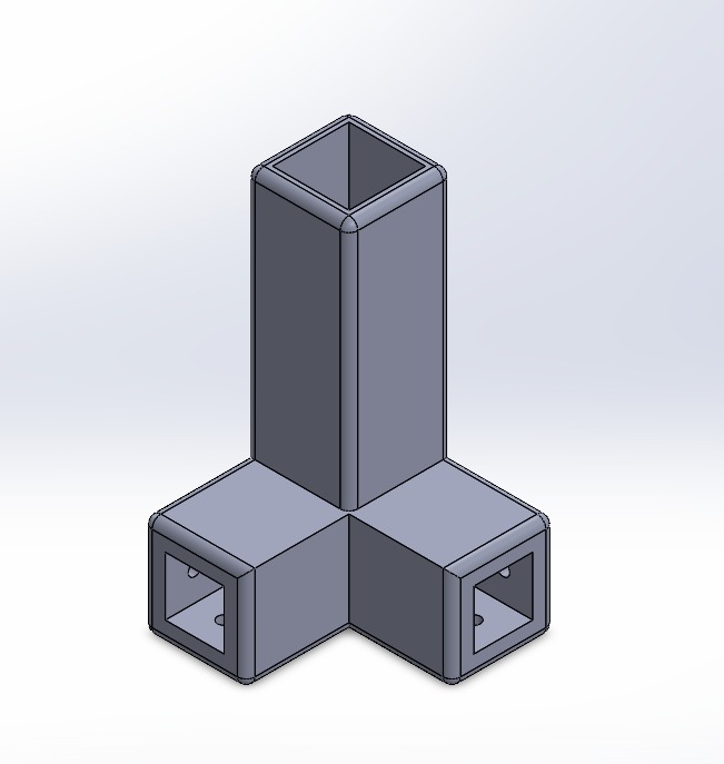
The support parts for the NEMA motor were also made, we used the NEMA datasheet, and that is how the basic structure of our machine ended up.
How it was built
1. Vertical Support Structure
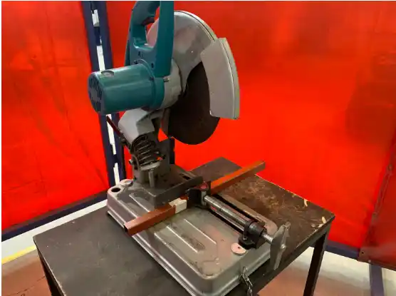
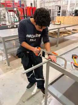
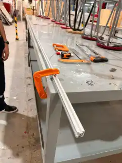
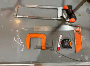
For the gantry base and the vertical supports, metal bars precision-cut using a circular metal saw were used. Dimensions were standardized to 50 mm to ensure the symmetry of the structure.
Once the segments were obtained, the fastening perforations were made. Using the connection elbows as a guide or template, the joining points were marked and drilled to ensure the centers matched.
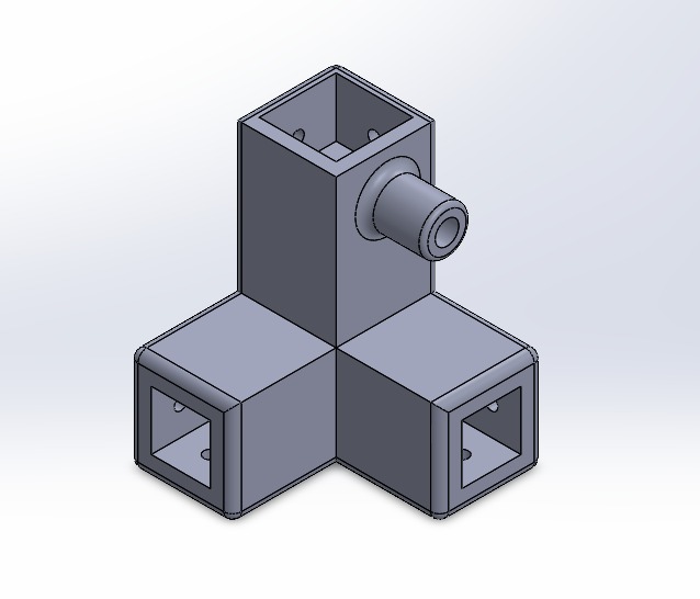
To allow the direct anchoring of the bolts, a manual threading process was performed using an M4 x 0.7 mm tap. This procedure consisted of:
- The gradual insertion of the tool to generate the internal thread.
- Advancing until overcoming the conical section of the tap tip, ensuring a functional thread throughout its depth.
- Cleaning the hole to allow a fluid threading of the M4 screws.
2. Aluminum Profile Frame
The horizontal structure was formed using 20x20 mm aluminum profiles. Sizing was initially done with a hacksaw, followed by a lathe facing process to ensure perfectly perpendicular cuts at 35 mm.
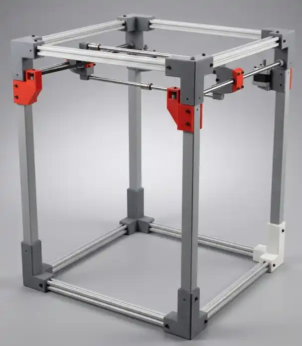
To guarantee a tight and aesthetic coupling between the profiles and the connectors, deburring and surface finishing with fine files was carried out. This eliminated irregularities on the cut faces, allowing the parts to fit optimally without mechanical play.
3. Assembly and Adjustment
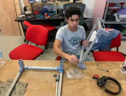
The final assembly was carried out by integrating the profiles into their respective joining elbows using a fastening nut system. The method consisted of presenting the screw with the nut at the end to facilitate its insertion into the profile slot. Once positioned at the required technical height, the final tightening was carried out, achieving a rigid and aligned structure, ready to receive the LM8UU linear bearings and the traction system.
Claw
Regarding the claw, an articulated mechanism was designed that would work with a central actuator to transition from rotational to linear motion, so that, with a central base point, it moves while another remains static, thus allowing the mechanical design itself to achieve the closing of the tips.
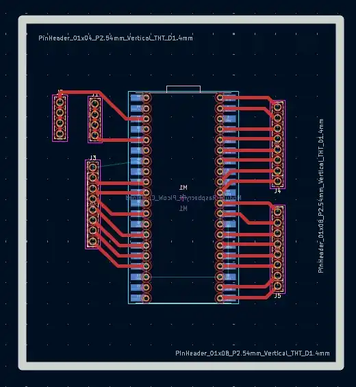
Electronics
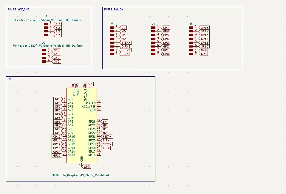
For the electronics, 3 boards were designed: one for the Pi Pico 2 where there were output pins; this design was made in KiCad because in this software the Pico footprint includes the holes to drill the board to place female pins to be able to attach and remove the Pico.
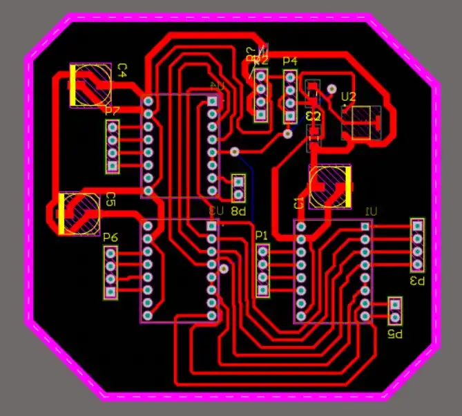
Afterwards, the board with the drivers (DRV8825) was made, 2 for the X axis and one for the Y axis; this is how the drivers were connected:
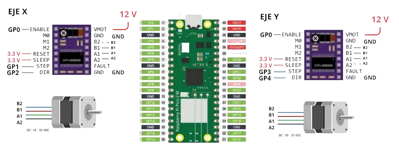
Then we connected a joystick to move both axes; it is important that the joystick outputs must go to analog pins.
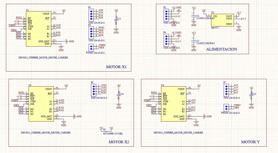
To power the reset and sleep pins, a voltage regulator (AMS1117) is placed which will lower the voltage from 12v to 3.3v; it was important to place the capacitors at the input and output of the regulator.
Code
#include <AccelStepper.h>

#define ENA_PIN   0
#define STEP_X    1
#define DIR_X     2
#define STEP_Y    3
#define DIR_Y     4

#define JOY_X     27
#define JOY_Y     26

const float MAX_SPEED  = 400.0;
const float ACCEL      = 800.0;

AccelStepper motorX(AccelStepper::DRIVER, STEP_X, DIR_X);
AccelStepper motorY(AccelStepper::DRIVER, STEP_Y, DIR_Y);

enum EstadoMov { DETENIDO, POSITIVO, NEGATIVO };
EstadoMov estadoX = DETENIDO;
EstadoMov estadoY = DETENIDO;

const long META_LEJANA = 1000000;
bool origenGuardado = false;

const int AIN1 = 8; const int AIN2 = 9; const int PWMA = 10;
const int BIN1 = 11; const int BIN2 = 12; const int PWMB = 13;
const int STBY = 14;
const int pinBoton = 15;

const long amarilloBaja = 700;
const long amarilloSube = 800;
const long poluluCerrar  = 1550;
const long poluluAbrir   = 1500;

const int potenciaAmarillo = 100;
const int potenciaPolulu   = 255;

bool estadoAnteriorBoton;

void setup() {
  Serial.begin(115200);

  while (!Serial && millis() < 4000);

  pinMode(ENA_PIN, OUTPUT);
  digitalWrite(ENA_PIN, LOW);

  motorX.setMaxSpeed(MAX_SPEED);
  motorX.setAcceleration(ACCEL);
  motorY.setMaxSpeed(MAX_SPEED);
  motorY.setAcceleration(ACCEL);

  pinMode(pinBoton, INPUT);

  pinMode(AIN1, OUTPUT); pinMode(AIN2, OUTPUT); pinMode(PWMA, OUTPUT);
  pinMode(BIN1, OUTPUT); pinMode(BIN2, OUTPUT); pinMode(PWMB, OUTPUT);
  pinMode(STBY, OUTPUT);
  digitalWrite(STBY, HIGH);

  delay(100);
  estadoAnteriorBoton = digitalRead(pinBoton);

  Serial.println("\n=== PICO 2 INICIADA Y CONECTADA ===");
  Serial.println("PASO 1: Mueve los NEMA con el joystick a la posicion de soltar.");
  Serial.println("PASO 2: Escribe 'O' (y presiona Enter) para FIJAR EL ORIGEN.");
  Serial.println("ATENCION: La garra esta BLOQUEADA hasta que guardes el origen.");
}

void loop() {
  if (Serial.available() > 0) {
    char comando = Serial.read();
    if (comando == 'O' || comando == 'o') {
      motorX.setCurrentPosition(0);
      motorY.setCurrentPosition(0);
      origenGuardado = true;
      Serial.println("\n>>> [EXITO] ORIGEN GUARDADO. BOTON DESBLOQUEADO <<<");
      Serial.println("Ya puedes empezar a jugar.");
    }
  }

  bool estadoActualBoton = digitalRead(pinBoton);

  if (estadoActualBoton == HIGH && estadoAnteriorBoton == LOW) {
    delay(50);
    if (digitalRead(pinBoton) == HIGH) {
      if (origenGuardado) {
        ejecutarRutinaYProgramarRetorno();
      } else {
        Serial.println("\n[ERROR] No puedes usar la garra aun. Fija el origen enviando 'O' primero.");
      }
    }
  }
  estadoAnteriorBoton = estadoActualBoton;

  gestionarJoystick();

  motorX.run();
  motorY.run();
}

void gestionarJoystick() {
  int lecturaX = analogRead(JOY_Y);
  int lecturaY = analogRead(JOY_X);
  int limiteSup = 600;
  int limiteInf = 400;

  if (lecturaX > limiteSup) {
    if (estadoX != POSITIVO) { motorX.moveTo(motorX.currentPosition() + META_LEJANA); estadoX = POSITIVO; }
  } else if (lecturaX < limiteInf) {
    if (estadoX != NEGATIVO) { motorX.moveTo(motorX.currentPosition() - META_LEJANA); estadoX = NEGATIVO; }
  } else if (estadoX != DETENIDO) {
    motorX.stop(); estadoX = DETENIDO;
  }

  if (lecturaY > limiteSup) {
    if (estadoY != POSITIVO) { motorY.moveTo(motorY.currentPosition() + META_LEJANA); estadoY = POSITIVO; }
  } else if (lecturaY < limiteInf) {
    if (estadoY != NEGATIVO) { motorY.moveTo(motorY.currentPosition() - META_LEJANA); estadoY = NEGATIVO; }
  } else if (estadoY != DETENIDO) {
    motorY.stop(); estadoY = DETENIDO;
  }
}

void ejecutarRutinaYProgramarRetorno() {
  Serial.println("\n>>> INICIANDO RUTINA DE GARRA...");

  moverAmarillo(false, amarilloBaja);
  delay(2000);

  moverPolulu(true, poluluCerrar);
  delay(500);

  moverAmarillo(true, amarilloSube);
  delay(3000);

  Serial.println(">>> Regresando al origen con la carga...");
  motorX.moveTo(0);
  motorY.moveTo(0);

  while (motorX.distanceToGo() != 0 || motorY.distanceToGo() != 0) {
    motorX.run();
    motorY.run();
  }

  Serial.println(">>> En origen. Esperando 2 segundos...");
  delay(2000);

  moverPolulu(false, poluluAbrir);
  Serial.println(">>> Garra abierta. Premio soltado.");

  Serial.println(">>> Control manual reactivado.");
}

void moverAmarillo(bool sube, long ms) {
  digitalWrite(AIN1, sube ? LOW : HIGH);
  digitalWrite(AIN2, sube ? HIGH : LOW);
  analogWrite(PWMA, potenciaAmarillo);
  delay(ms);
  frenarMotor(true);
}

void moverPolulu(bool sube, long ms) {
  digitalWrite(BIN1, sube ? LOW : HIGH);
  digitalWrite(BIN2, sube ? HIGH : LOW);
  analogWrite(PWMB, potenciaPolulu);
  delay(ms);
  frenarMotor(false);
}

void frenarMotor(bool esAmarillo) {
  if (esAmarillo) {
    digitalWrite(AIN1, HIGH); digitalWrite(AIN2, HIGH);
    analogWrite(PWMA, 0);
  } else {
    digitalWrite(BIN1, HIGH); digitalWrite(BIN2, HIGH);
    analogWrite(PWMB, 0);
  }
}
FILES
Download the source files created during this week: