What is a CNC?
A CNC (Computer Numerical Control) machine is a motorized tool controlled by a computer that executes pre-programmed sequences of commands to manufacture parts with high precision. Unlike manual machining, where an operator moves the tools by hand using wheels and levers, a CNC machine uses software to translate a digital design into physical movement.
Building a CNC
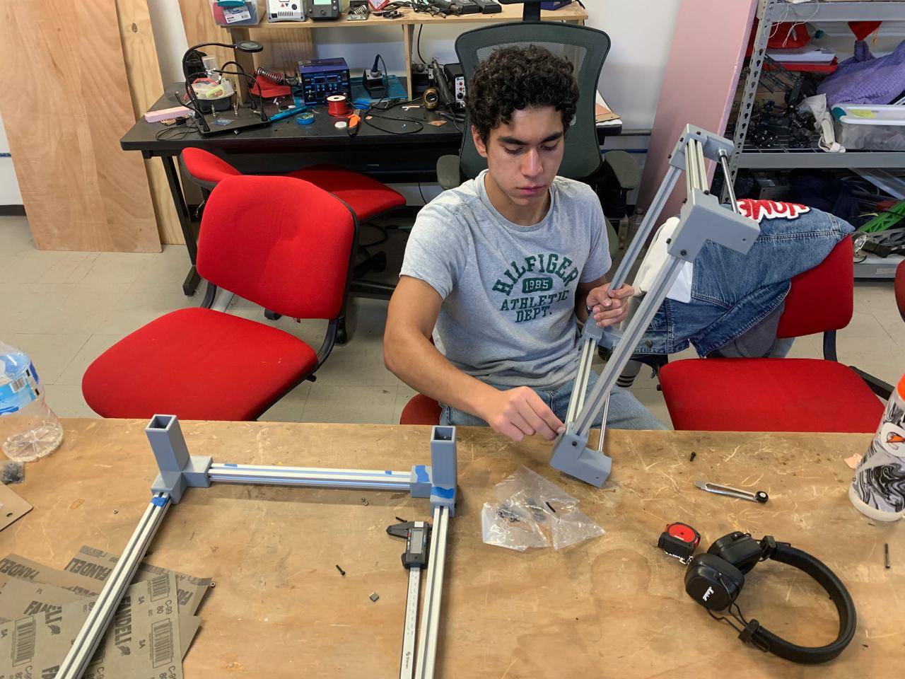
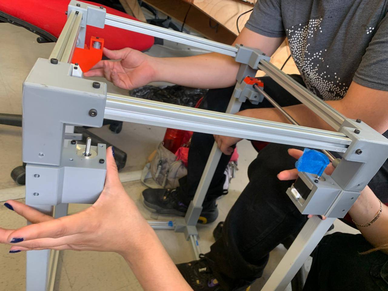
This week we worked as a team to create a candy claw, similar to the ones for plush toys in shopping malls. My part of the job consisted of preparing the physical structure, from cutting the profiles to the final assembly.
2D Vectorization Process
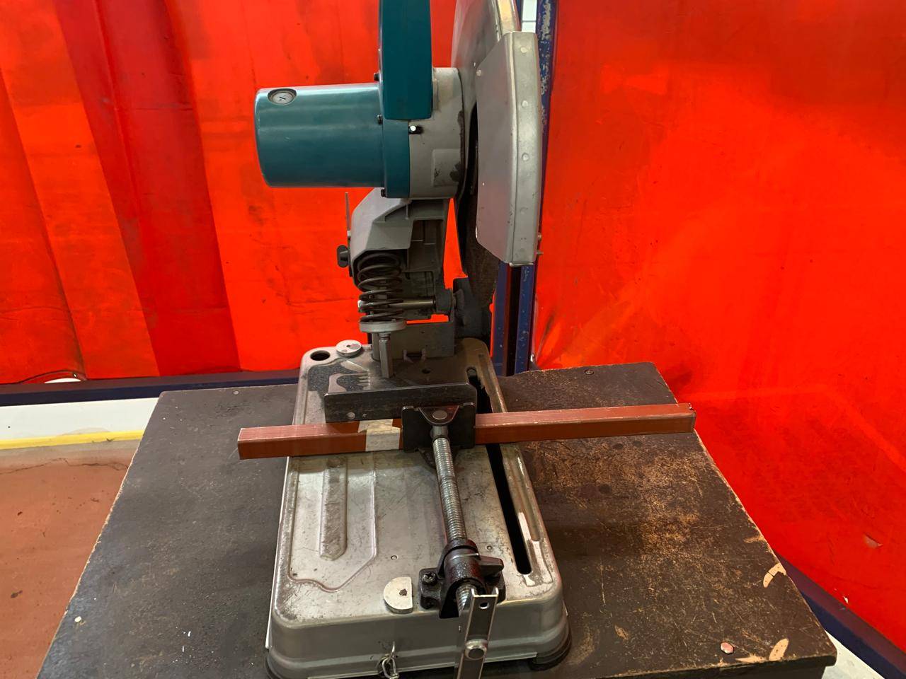
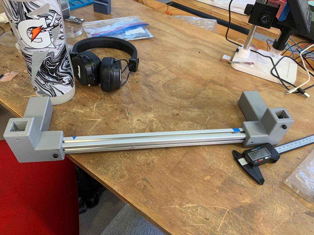
Vertical supports
For the gantry base and vertical supports,I used precision-cut metal bars, cut with a circular saw. The dimensions were standardized to 50 mm to ensure the symmetry of the structure.
Trace Bitmap
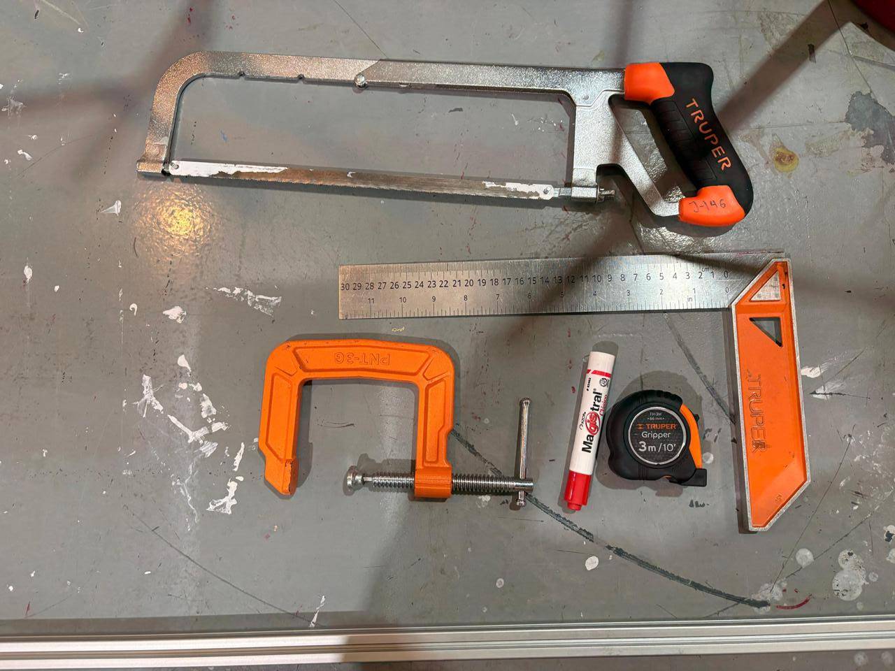
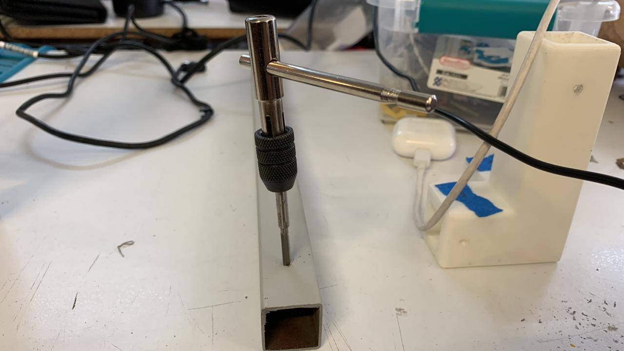
To cut the profiles, use a hacksaw to ensure a clean and straight cut, as well as a carpenter's ruler to ensure a 90-degree angle. We used 20 x 20 profiles with a length of 35 mm.
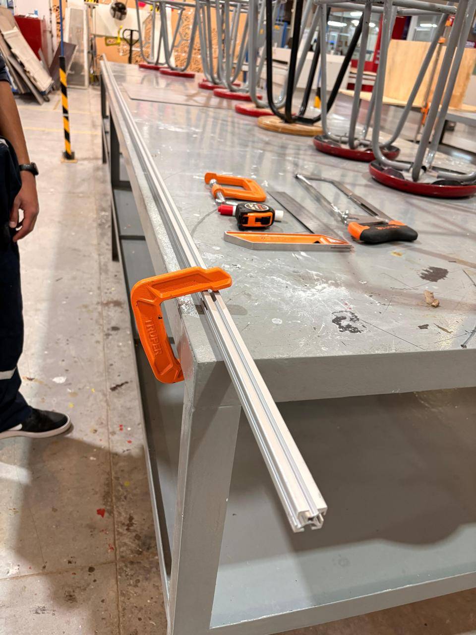
C-clamp
To be able to cut the profiles without making mistakes, I used a C-clamp to immobilize the piece.
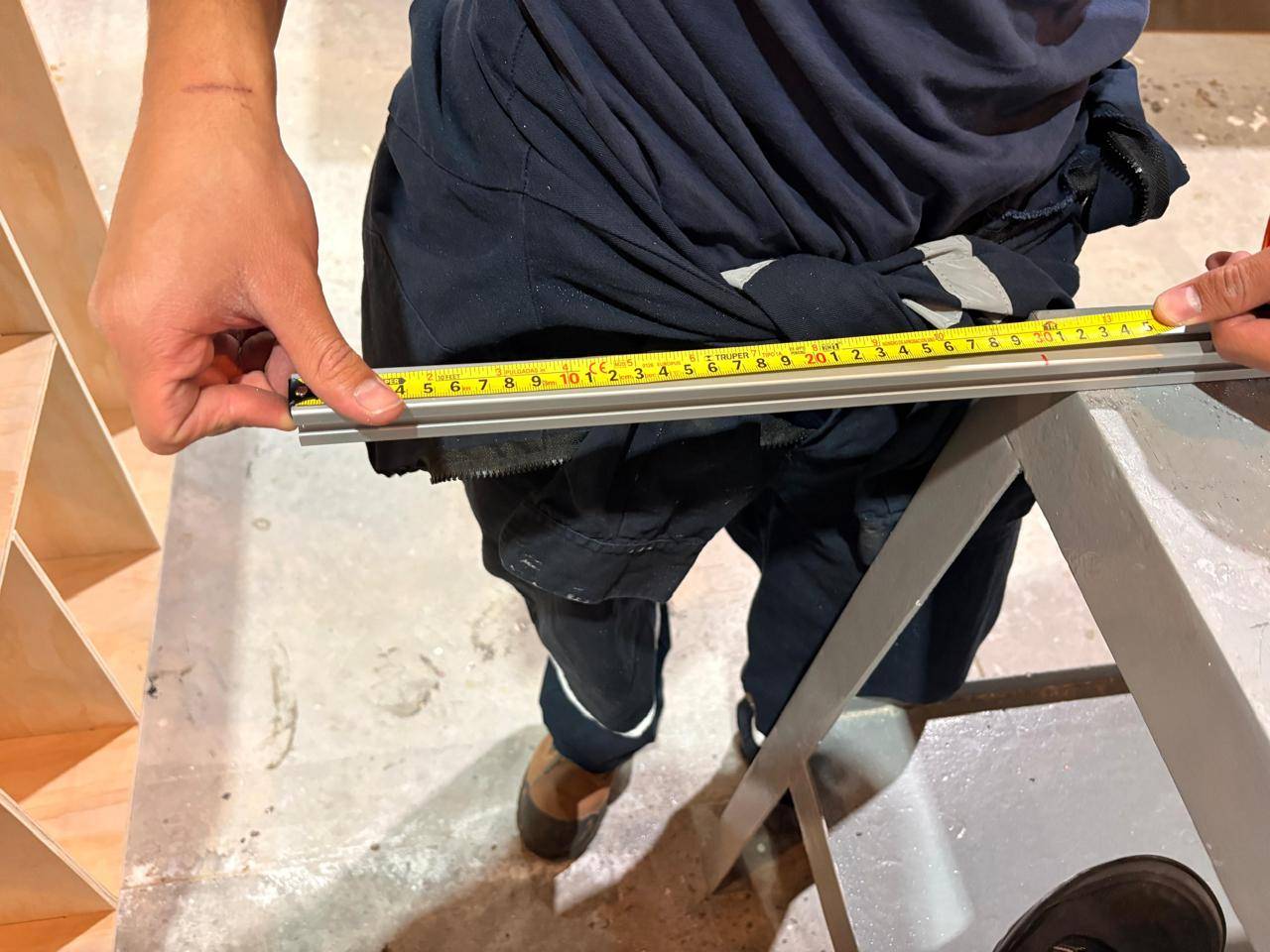
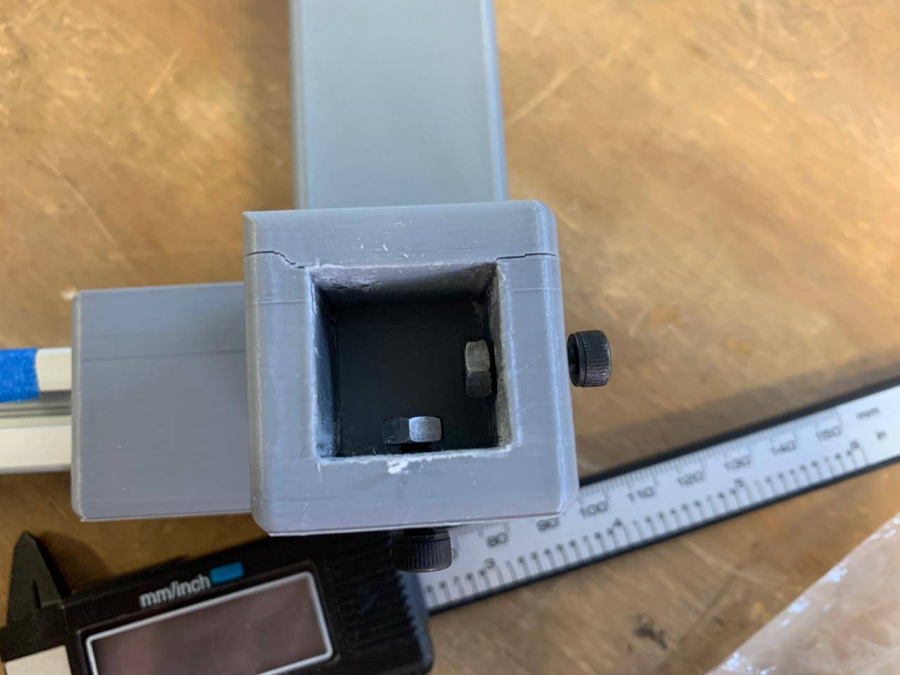
Meassuring
Measure the profiles with a tape measure and then check the cutting angle with a carpenter's ruler, ensuring an exact length of 35 mm in each piece.
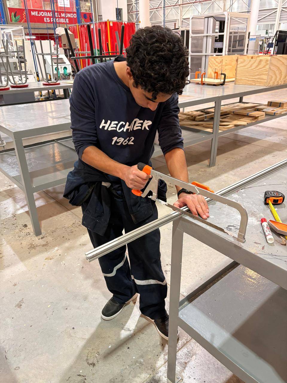
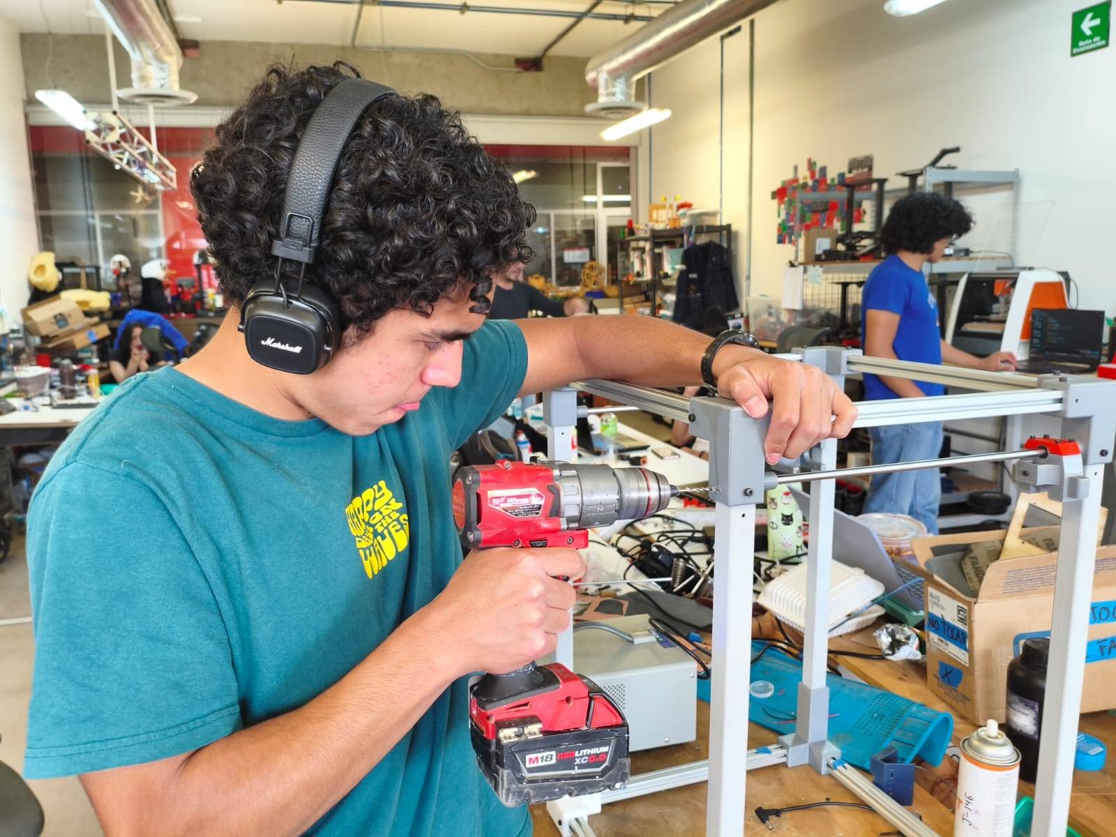
Cutting
I proceeded to cut the profiles carefully with a hacksaw to avoid warping the piece.
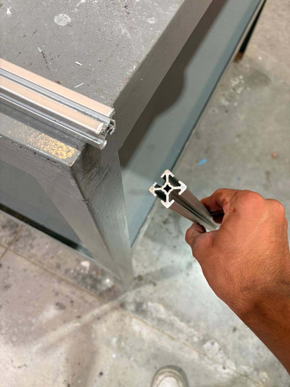
Surface result
Although the cuts came out very clean, the faces of the profiles had to be smoothed to ensure that they were completely flat.
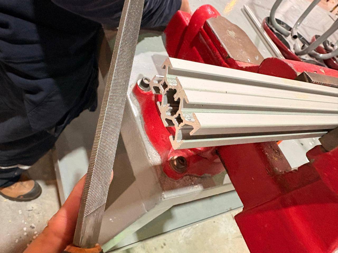
Final step
To achieve this superior finish, use a file to personally control the process, thus giving it a clean finish.
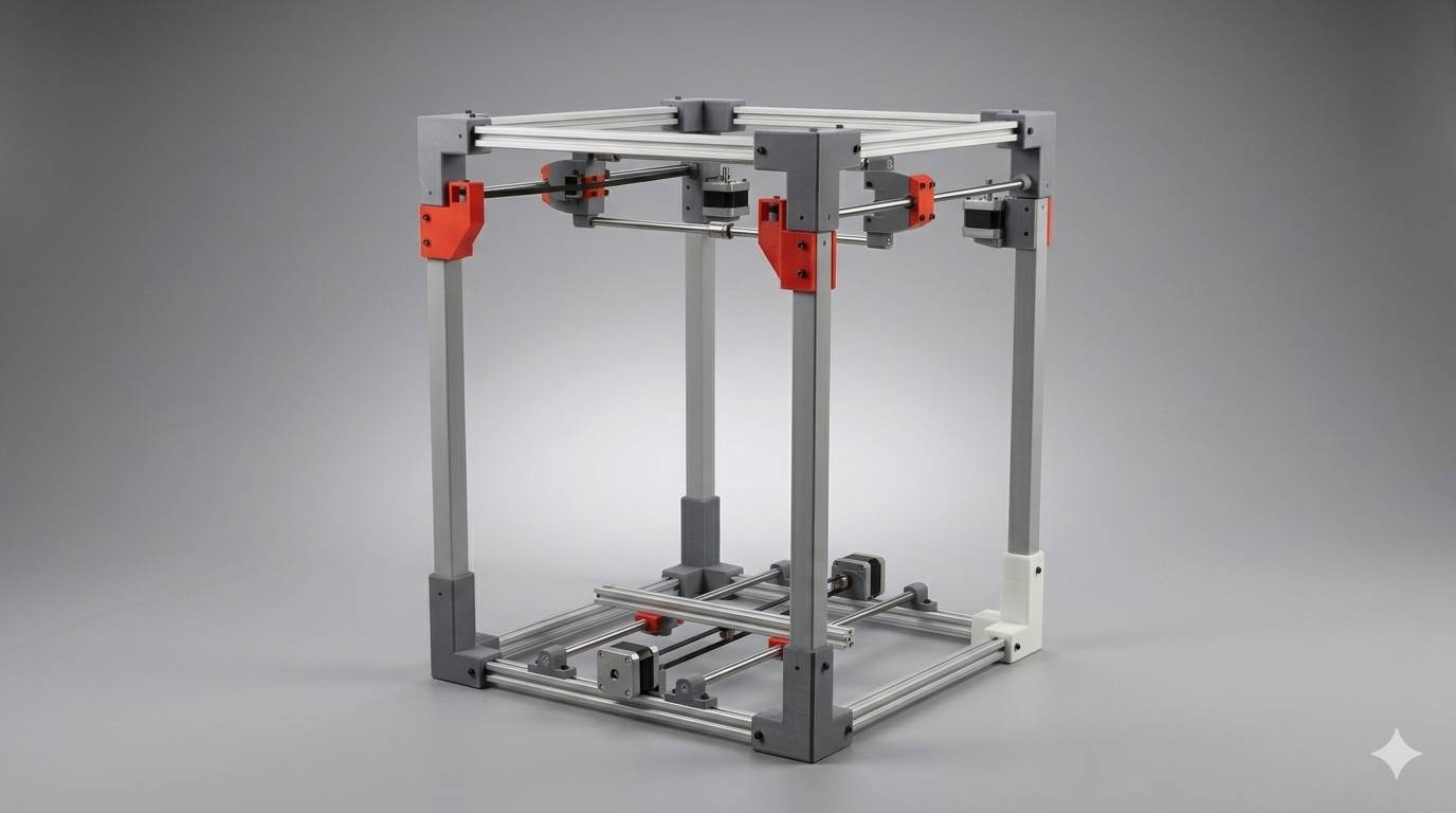
[ CNC_MACHINING: FINAL STRUCTURE ]
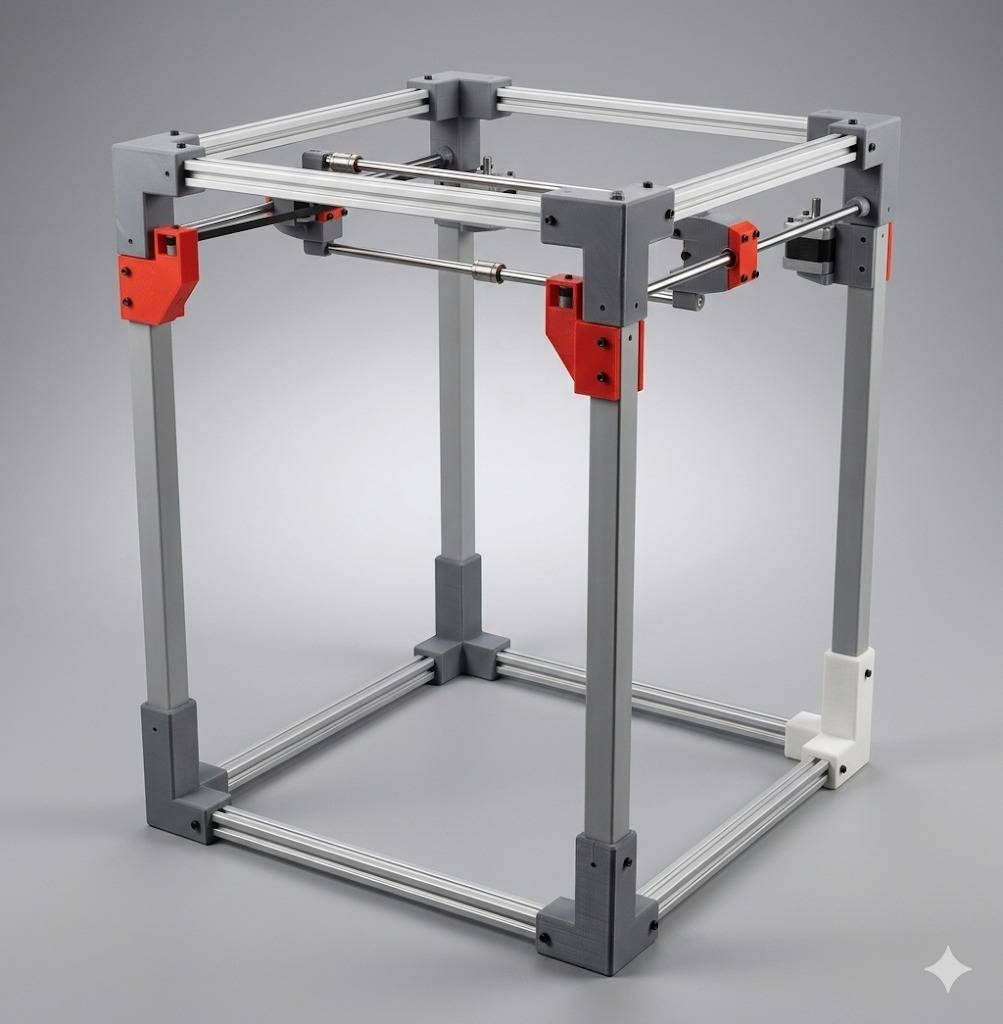
DET_01: ISO_VIEW_MASTER
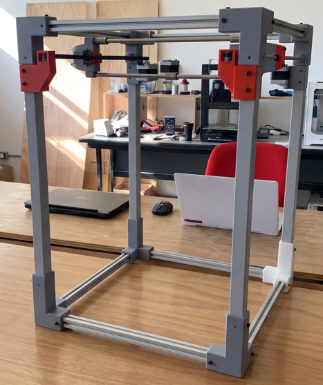
DET_02: TOP_SURFACE_FINISH