12. Machine Design
Design
This week we worked together with other members of FabLab Puebla; we wanted to create a machine inspired by a claw machine. If you want to see the complete machine's documentation, you can view it on the GROUP PAGE.
My part of the development consisted of designing the base structure of the machine in SolidWorks. First, I created the joints, taking into account that I would use 20 mm profiles for the base squares and 26 mm bars for the machine's height. In the joints, I added holes for screws to ensure the pieces were more secure.
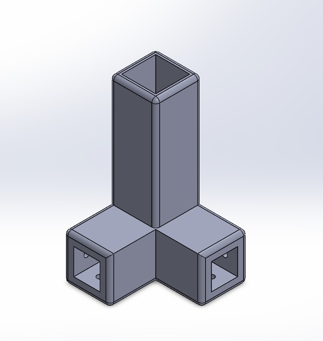
For the bottom joints, the 26 mm tube was inserted 6 cm deep. For the top joints, I did the same, but the 26 mm bar only enters about 2.5 cm; this was to avoid losing height for the carriage design since we want a claw that moves up and down. I also added small connectors to place the smooth rod.
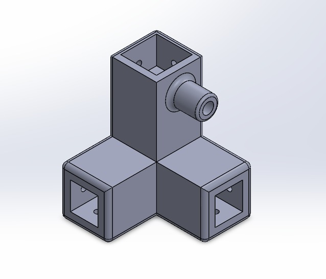
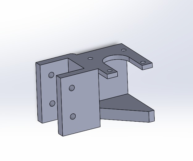
I was also in charge of designing a piece where the 26 mm bar could be placed to serve as the support for our NEMA motor.
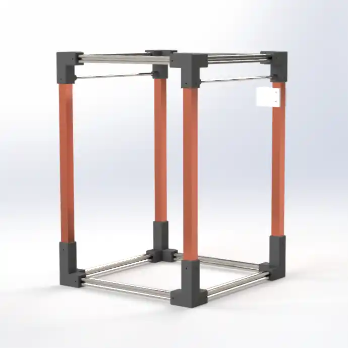
Finally, I was responsible for the machine's assembly so my teammates could dimension it to create their corresponding tasks.
Electronics
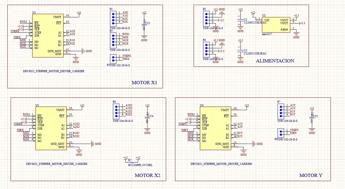
Another task I was responsible for was the electronics. We will use 3 NEMA motors: 1 for the X-axis and 2 for the Y-axis. To control them, we used DRV8825 drivers and a Pi Pico 2.
First, I designed the motor board in Altium; this is what the schematic looks like.Afterwards, the board with the drivers (DRV8825) was made, 2 for the X axis and one for the Y axis. To power the reset and sleep pins, a voltage regulator (AMS1117) is placed which will lower the voltage from 12v to 3.3v; it was important to place the capacitors at the input and output of the regulator; this is how the drivers were connected:
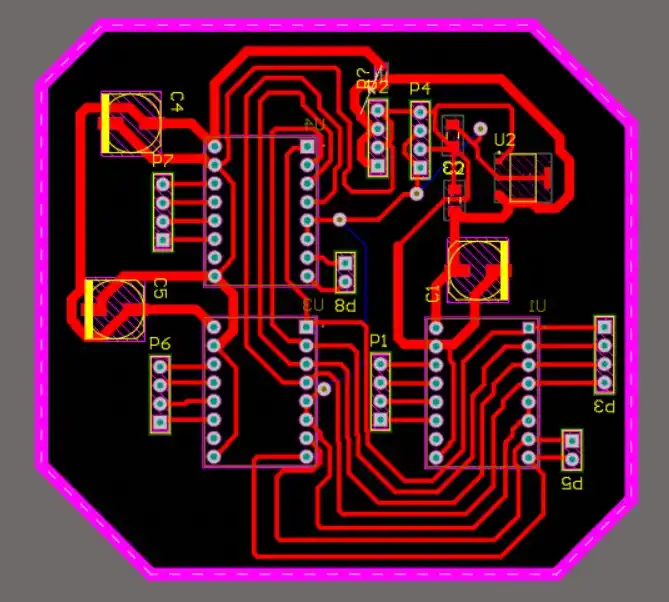
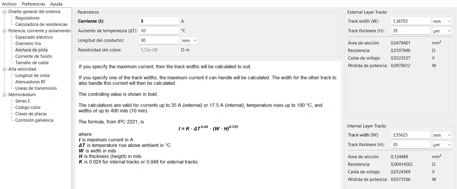
For the sections where the motor voltage (12V) is connected, I set a track width of 2 mm according to the KiCad calculator.
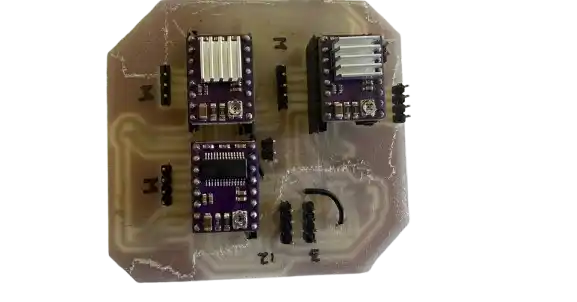
To make the Pico board, I used KiCad because I wanted to include the perforations for female headers to be able to attach and remove my Pico. This option was simpler in KiCad because the Pico footprint already includes the holes. I only placed the Pico pins and the output pins.
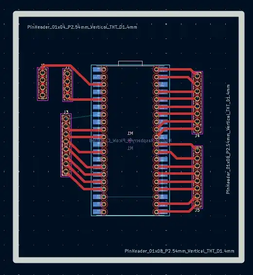
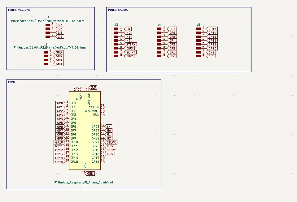
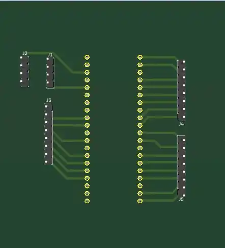
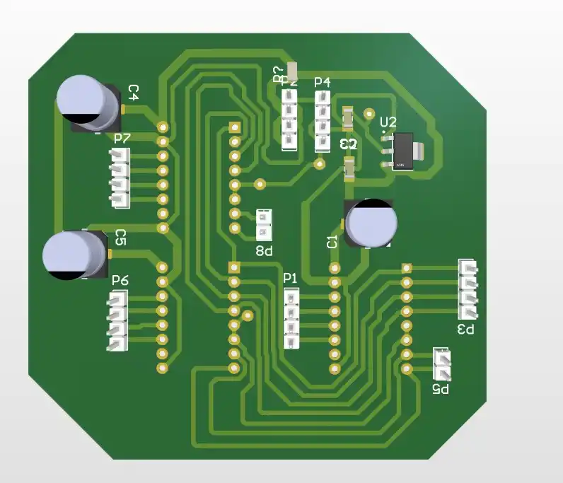
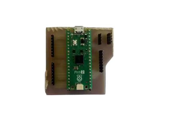
This was the final result of the boards.
Code to test
#include <AccelStepper.h>

#define enablePin 0
#define stepPin1  1
#define dirPin1   2
#define stepPin2  3
#define dirPin2   4

// Movement settings
const float vMax = 800.0;    // A little slower for stability
const float accel = 1600.0;   // Smooth acceleration
const long tramo = 5000;     // Steps per lap

AccelStepper stepper1(1, stepPin1, dirPin1);
AccelStepper stepper2(1, stepPin2, dirPin2);

// Direction variables
int dir1 = 1;
int dir2 = -1;

void setup() {
  pinMode(enablePin, OUTPUT);
  digitalWrite(enablePin, LOW);

  stepper1.setMaxSpeed(vMax);
  stepper1.setAcceleration(accel);

  stepper2.setMaxSpeed(vMax);
  stepper2.setAcceleration(accel);

  stepper1.moveTo(tramo);
  stepper2.moveTo(-tramo);
}

void loop() {
  if (!stepper1.isRunning()) {
    dir1 *= -1;
    long nuevaMeta1 = (dir1 == 1) ? tramo : 0;
    stepper1.moveTo(nuevaMeta1);
  }

  if (!stepper2.isRunning()) {
    dir2 *= -1;
    long nuevaMeta2 = (dir2 == 1) ? 0 : -tramo;
    stepper2.moveTo(nuevaMeta2);
  }

  stepper1.run();
  stepper2.run();
}