Final Project
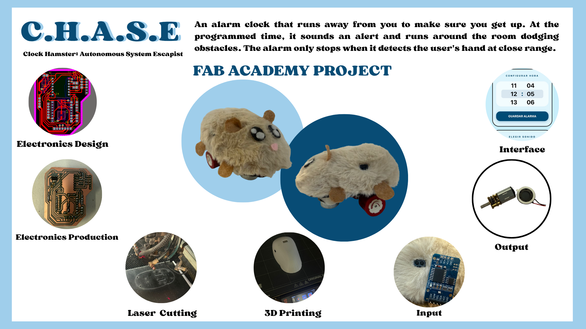
My favorite activity is sleeping. I often turn off my alarm to keep sleeping, but because of that, I sometimes arrive late to places. That is why I wanted to make an alarm for my project that would be harder for me to turn off, so I thought of an alarm that tries to escape.
My boyfriend always says I am like a hamster (small and easily scared), so I thought I would love for my project to be shaped like a hamster to make it funny.
I think I could do the electronics with a Xiao, use molds to make the hamster shape, and laser cutting for the internal structure, as well as 3D printing. I also want to make an interface to set the alarms.
This is a bit of what I think I could do, but as I advance in the Fab path, I will clarify my ideas.
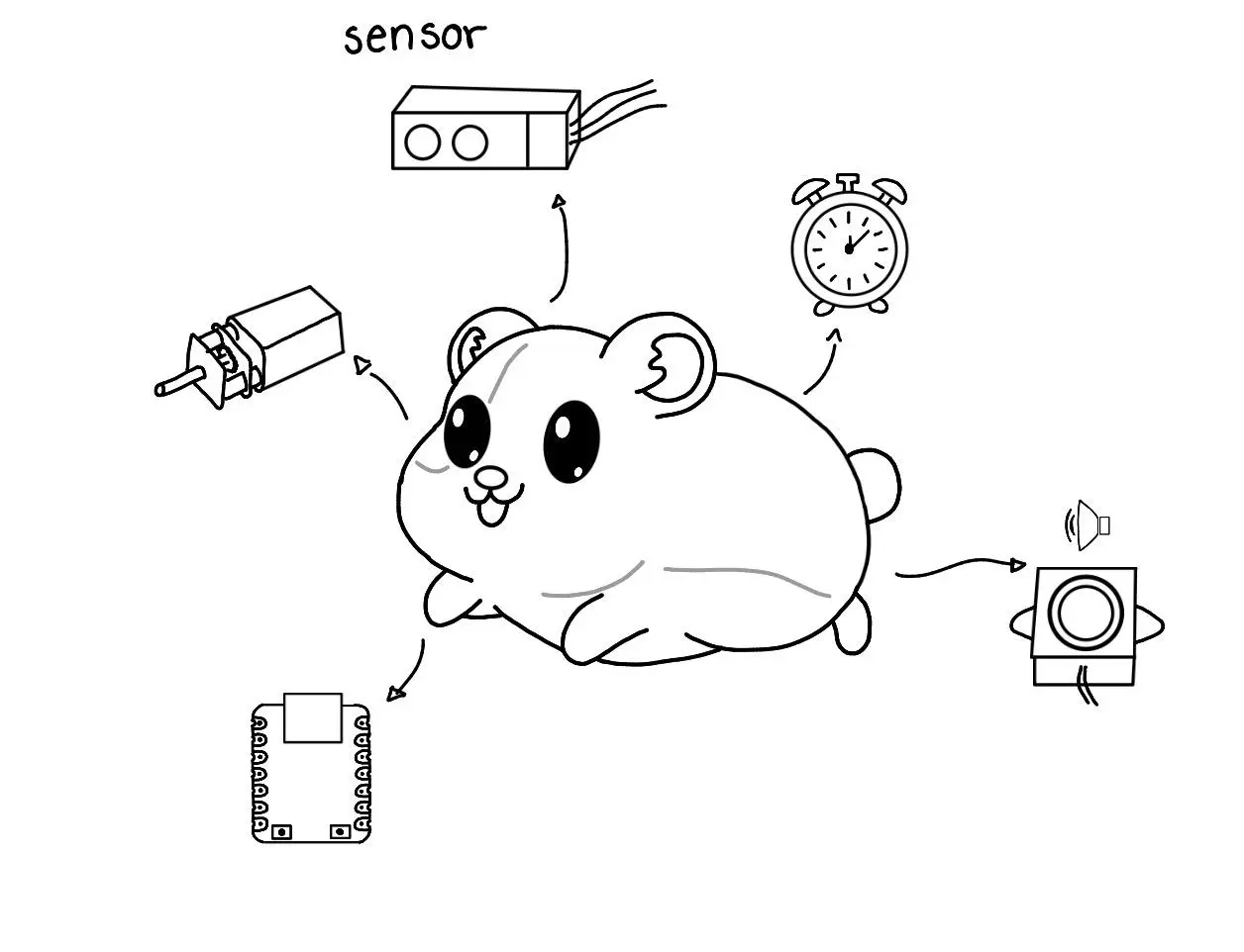
Systems integrating my project:
- Motion System: Includes the motors and drivers to allow movement through the environment.
- Navigation System: I will place sensors so that it tries to flee from the user.
- Control System: A clock sensor and a microcontroller to read the time to activate the alarm.
- Structure: Includes the design and 3D printing of the hamster shape.
Plan for the next weeks:
- Computer-Aided Design: Design the 3D model of the hamster and the internal structure.
- Computer-Controlled Cutting: Prototype the internal structure using MDF to test the fit of the components.
- Electronics Design/Production: Design a PCB for the Xiao that connects the motor drivers and sensors.
- Molding and Casting: Create the final exterior "skin" of the hamster (likely using silicone or resin for a soft finish).
- Input Devices: Add sensors so the hamster tries to run away.
- Output Devices: Control the DC motors for the wheels and the buzzer for the alarm sound.
- Interface and Application Programming: Build a simple web or mobile interface to connect to the Xiao and configure the alarm time.
APRIL 2026
BILL OF MATERIALS
| Item | Details | Qty | Unit Price ($) | Source/Link |
|---|---|---|---|---|
| PCB | ||||
| Female pin | - | 25 | - | - |
| 10k resistor | 1206 smd | 1 | - | - |
| 0 resistor | 1206 smd | 3 | - | - |
| AMSL117 3.3v regulator | - | 1 | - | - |
| 0.1uF capacitor | 1206 smd | 2 | - | - |
| TB67H451AFNG | - | 1 | - | - |
| Attiny | 412 | 1 | - | - |
| XIAO-ESP32C6 | - | 1 | 7 | UElectronics |
| Mechanical | ||||
| PLA filament | - | - | 20 | InovaMarket |
| Black acrylic | 40.6 x 30.5 x 0.3 centimeters | 1 | 23 | Amazon |
| Plush fabric | - | 1 | 17 | - |
| Mini Wheel | - | 1 | 1.40 | AliExpress |
| Electronic Components | ||||
| Micro DC motor | 6V 300 RPM | 2 | 4 | AliExpress |
| RTC sensor | - | 1 | 4 | MercadoLibre |
| Copper | - | 1 | 6 | AliExpress |
| Speaker | - | 1 | 0.45 | AliExpress |
| DFplayer Mini MP3 | - | 1 | 2 | UElectronics |
| Analogic Sensor | 4-50 cm | 3 | 3 | AliExpress |
| Battery | 9V- 4200 mWh | 1 | 17 | Steren |
| TOTAL COST: $118.85 | ||||
MY FINAL PROJECT
3D DESIGN
SOLIDWORKS
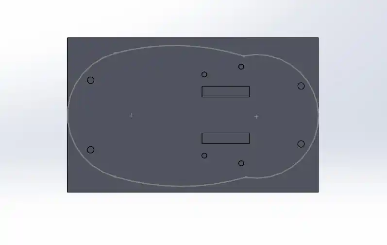
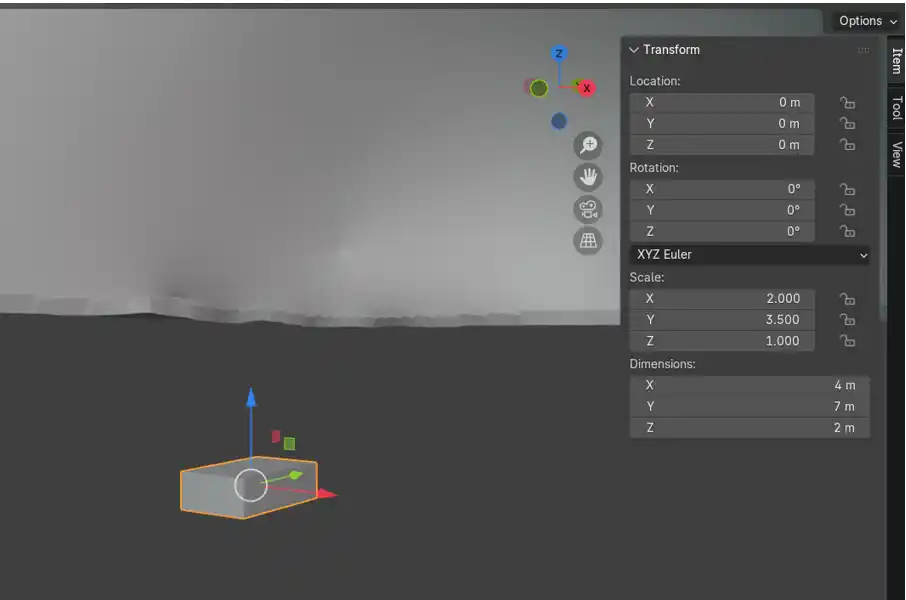
The first thing I did for my project was the shell in Blender to be able to visualize the available space I had, I made the base in SolidWorks to be able to add dimensions to my hamster, the base turned out like this:
To be able to see a little more about how to use SolidWorks you can check my WEEK02.
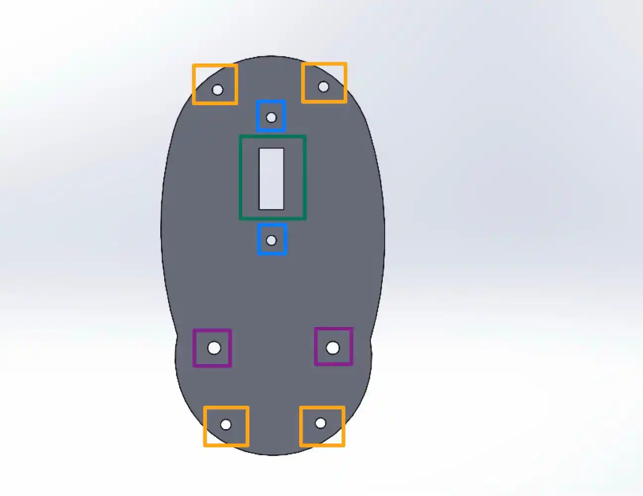
Where each of the parts has a function which is the following:
- Orange: to be able to place the screws with which we join the base and the shell.
- Blue: to be able to screw the N20 motor supports, where what I did was a support to give height to the motors and so the wheels do not stick out so much from the body.
- Green: to pass the cables with which we power the motors.
- Purple: to place the screws for the caster wheel that gives upper support to the base.
Then in SolidWorks I made a small sketch for the shell shape taking into account the size of the base, this is how my small sketch turned out.
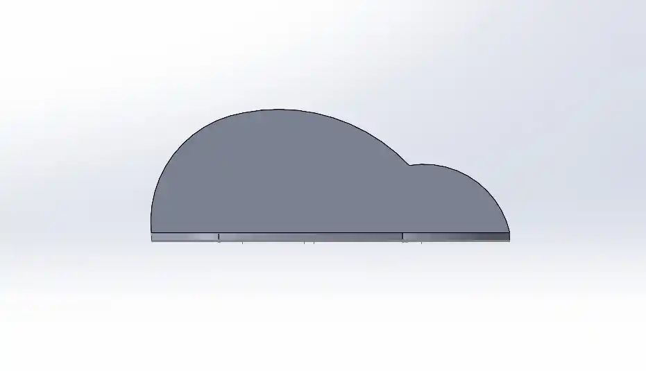
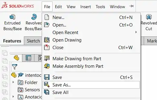
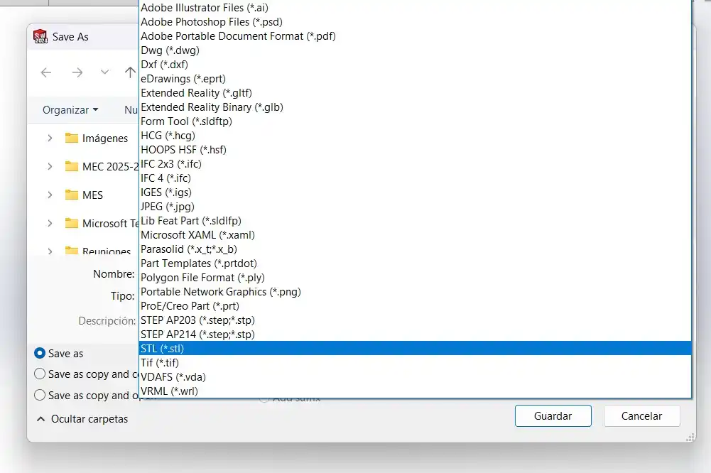
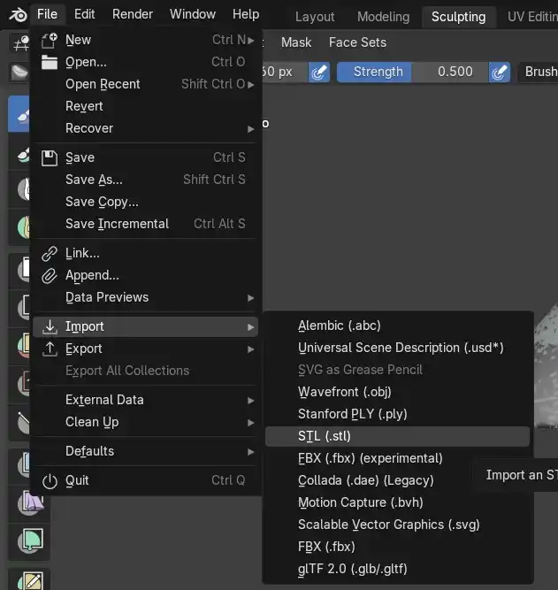
As you can see it looks too square this is because I did it in SolidWorks and here it is hard to make more organic shapes, so I saved it as an STL following these steps:
- Files> Save As..
- In the type menu we select STL.
BLENDER
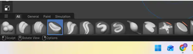
- We download the Blender application and open a new file and do the following: File > Import > STL
- In the Sculpting menu we can start to modify the square shape we made in SolidWorks, we do this with the bottom tools we have underneath.
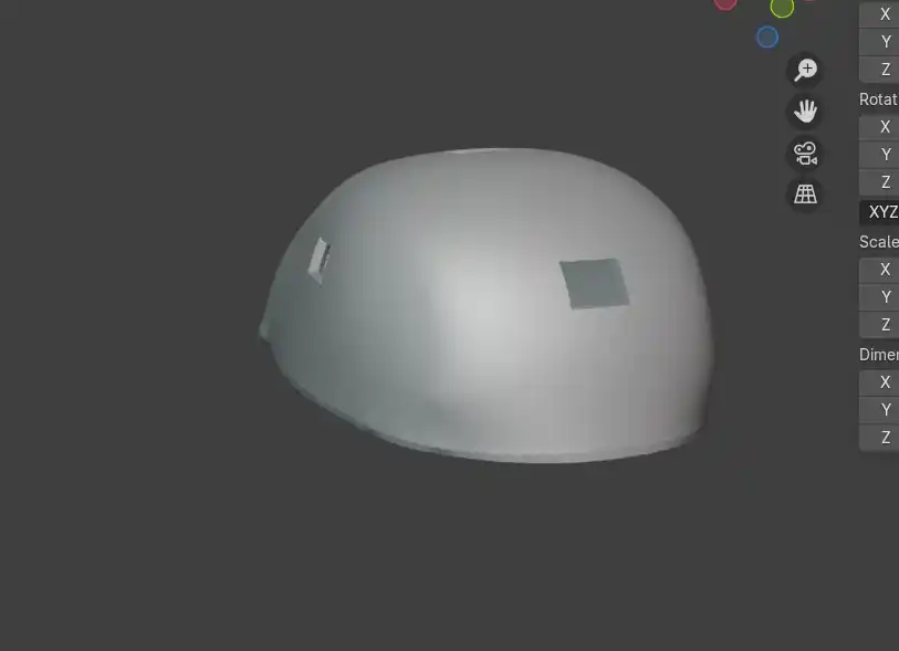
The result was the following: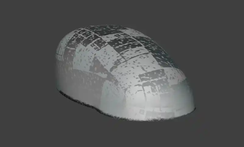

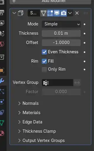
- But I needed the figure to be hollow and of greater thickness to be able to 3D print it, so to be able to have those modifications I did the following:
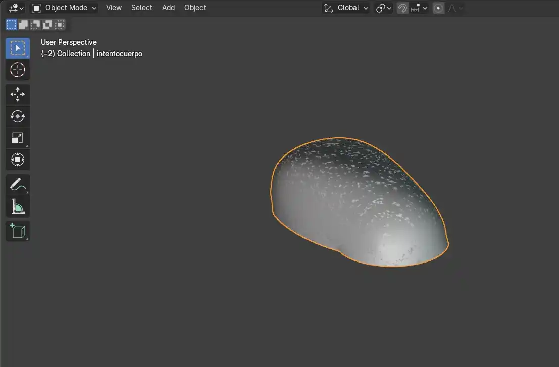
- Press the TAB key to switch modes, where we have two EDIT MODE and OBJECT MODE, to be able to give thickness to our shell we have to go to OBJECT mode and select the entire mesh.
- Then in the right menu on the blue wrench a modifiers menu will open.
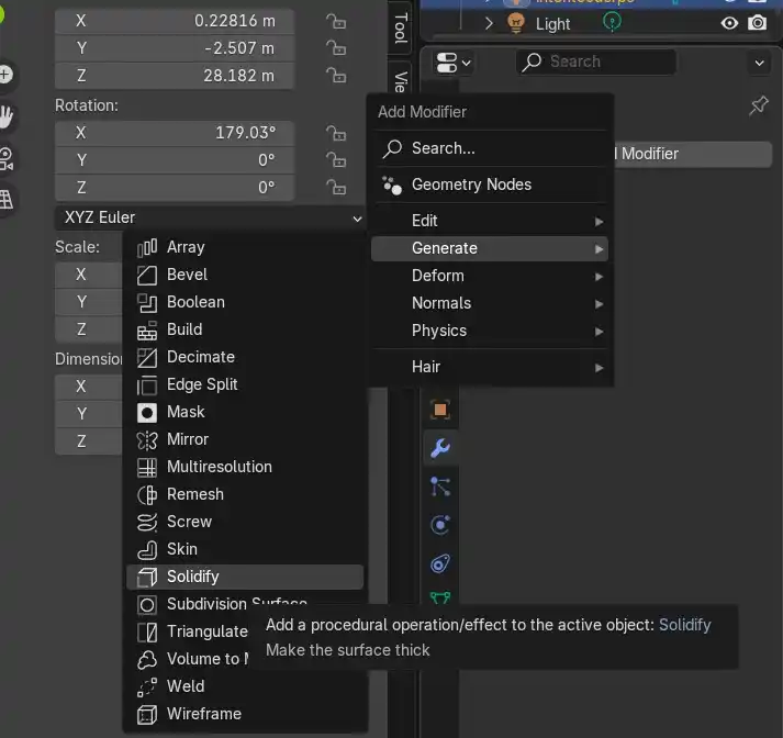
- Generate > Solidify
- We change the thickness according to the one we need which to be able to print it correctly can be between 0.8 to 1.2 mm but since the units are different in Blender we can see this by observing the change that our piece has.
- To confirm this operation on our figure we must press Ctrl + A and that's it we already have the first part of our hamster, only that we also must make the holes to put the sensors and the joints where we will put the screws to fit the base.
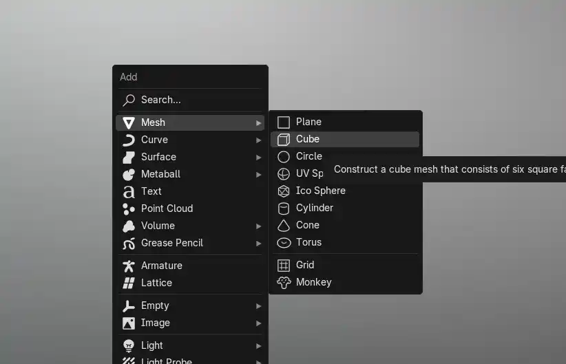
- In object mode we press Shift + A > Mesh > Cube.
- A cube will appear in the middle of our piece and in the right menu we can modify the dimensions of the cube.
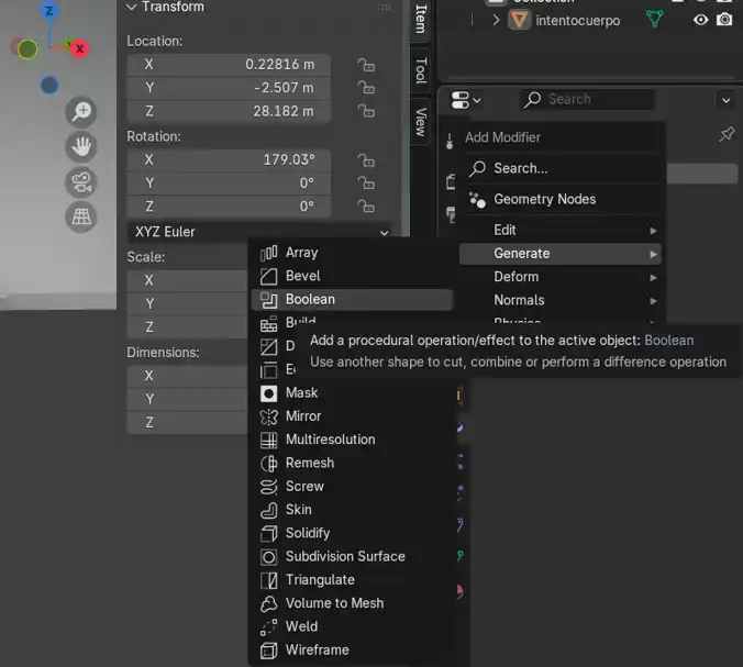
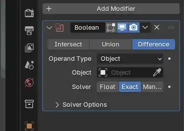
- We position where we are going to want the holes for the sensors and again we go to the blue wrench > Add Modifier > Generate > Boolean.
- We select Difference in Operand Type our main figure is selected and then with the eyedropper we select the cube we made to make the hole, this cube has to go through the whole figure and to confirm the operation Ctrl + A.
- Then we delete the cube and that is how my piece turned out with the holes for the three sensors.
- The only step we are missing is to put the screw joints where we do the following: Shift + A > Mesh > Cylinder. In the dimensions menu we put the radius according to the screws we are going to use.
- Then in edit mode we select the top face of the cylinder and press I and move our cursor inwards to make a new circle, then we press E and move the cursor downwards to make the hole.
- This is how the screw joints turned out and to fully join them to the main body what I did was select the main body > Modifier > Boolean > Union > With the eyedropper we select all the screw joints and to confirm it Ctrl + A.
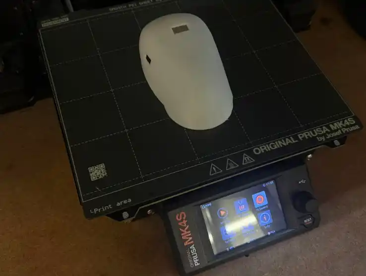
3D PRINTING
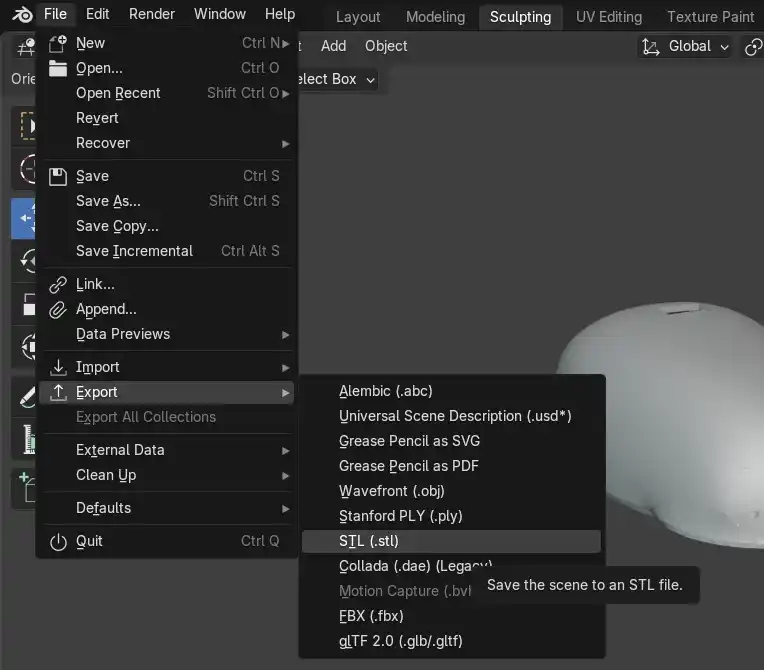
I exported my finished Blender model as STL: File> Export> STL and opened it in Prusa Slicer, to know more about the settings to 3D print you can see my WEEK05.
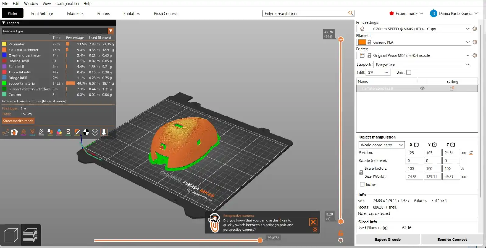
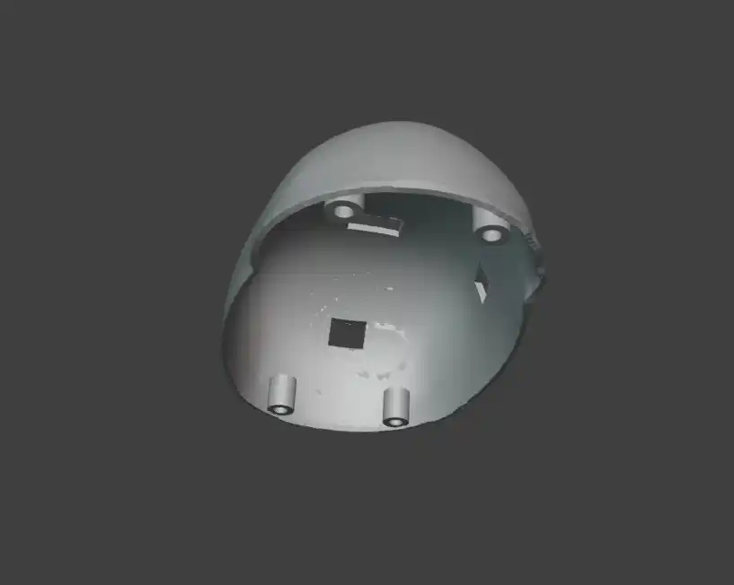
The result of my print was this
Since I had the 3D printed shell what I did was cover it with plush type fabric to give it a cuter touch the first version was this.

Although because of the color they told me it looked more like a rat so I decided to change the fabric and this is how it ended up, this is the version before I trimmed the excess fabric.

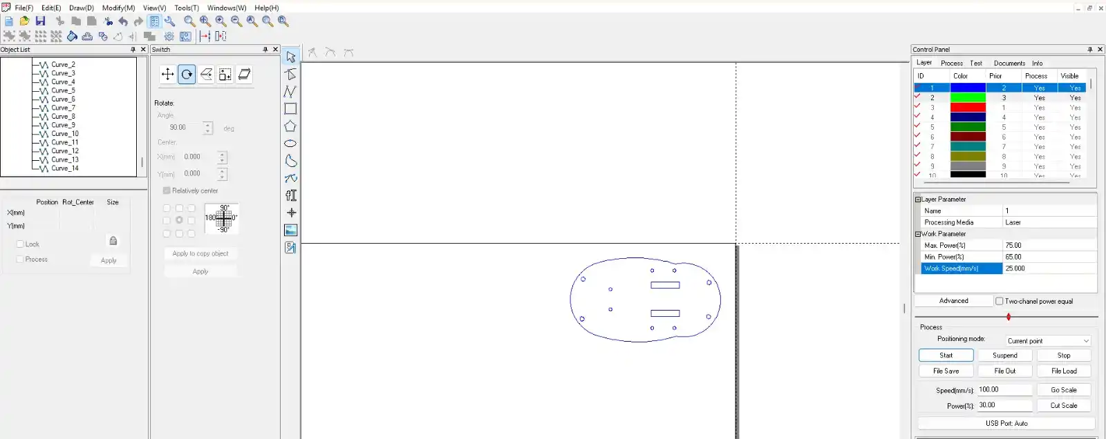
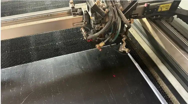
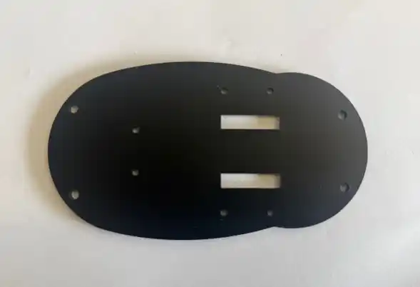
LASER CUTTING
For the base I decided to cut it with black acrylic to know more about how the laser cutter works you can see my WEEK03, the parameters to cut acrylic were the following:
- Max. Power % = 75
- Max. Power % = 65
- Work Speed = 25
INPUT
For inputs I used three things a capacitive sensor so that this serves as a button so that when it detects an increase in capacitance when the user grabs the hamster it turns off besides an RTC with which we can detect the time so that the speaker begins to sound and the motors move when it is equal to the time that the user set in the interface and finally the sensors that help prevent the hamster from getting trapped.
CAPACITIVE SENSOR
First I did some tests which I did during my WEEK09, this is the schematic of how the sensor works.
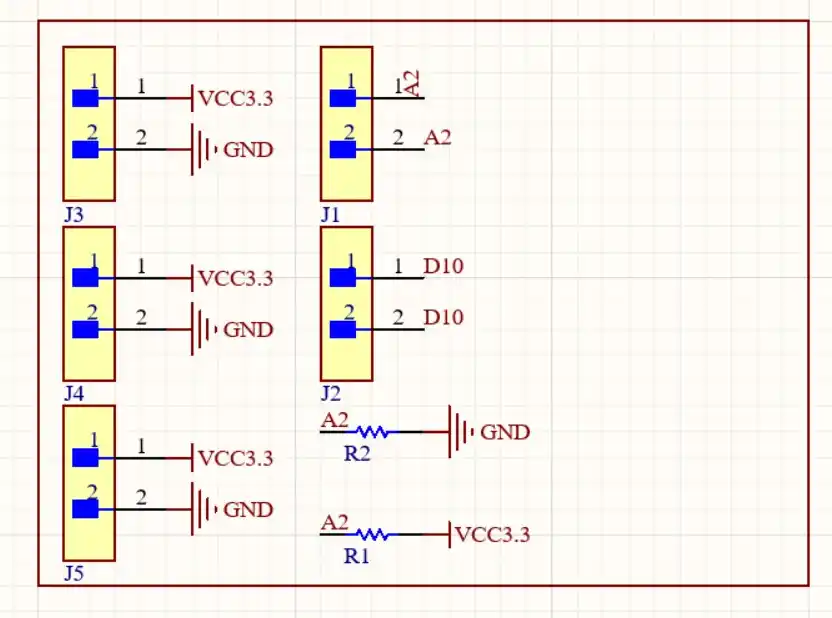
CODE
long result;            // Stores the total sum of samples
int analog_pin = A2;    // Receiver pin where capacitance is measured
int tx_pin = D10;       // Transmitter pin

void setup() {
  // Configures the transmitter pin as data output
  pinMode(tx_pin, OUTPUT);

  Serial.begin(115200);

  delay(1000);
}

long tx_rx() {
  int read_high;    // Variable for reading with active pulse
  int read_low;     // Variable for reading with deactivated pulse
  int diff;         // Difference between charge and discharge
  long sum = 0;     // Accumulator for all samples
  int N_samples = 100; // Number of measurements to average and reduce noise

  for (int i = 0; i < N_samples; i++) {

    digitalWrite(tx_pin, HIGH);
    read_high = analogRead(analog_pin);

    delayMicroseconds(100);

    digitalWrite(tx_pin, LOW);
    read_low = analogRead(analog_pin);

    diff = read_high - read_low;

    sum += diff;
  }

  return sum; // Returns the total of the 100 samples
}

void loop() {
  result = tx_rx();

  // Converts the summed value (approx range 15000-25000) to a scale of 0 to 1024
  long mapped_result = map(result, 15000, 25000, 0, 1024);

  Serial.print("Raw (Crudo): ");
  Serial.print(result);
  Serial.print(" | Mapped (Escalado): ");
  Serial.println(mapped_result);

  delay(50);
}
RESULT
Then I placed it on the internal part of my shell and did some tests of how much the values change when you place your hand over the hamster.
I2C SENSOR (RTC)
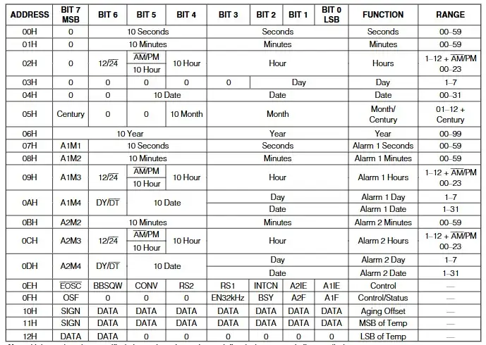
The first thing I did was test the Real-Time Clock (RTC) sensor for my hamster alarm clock, since with this reading the hamster will start ringing. This uses I2C communication. During WEEK09 you can find more information.
I used the dedicated pins on the XIAO (SDA and SCL). The microcontroller requests information from a specific address (e.g., 0x68), and the RTC responds by sending packets of bytes representing seconds, minutes, and hours.
The image below shows the registers through which the RTC operates; you can find this map in the datasheet.
#include <stdio.h>
#include "hardware/i2c.h"
#include "pico/binary_info.h"

// Hardware Configuration
#define I2C_PORT i2c1
#define PIN_SDA 6
#define PIN_SCL 7
#define DS3231_ADDR 0x68

// BCD conversion functions
uint8_t bcdToDec(uint8_t val) { return ((val / 16 * 10) + (val % 16)); }

void setup() {
  Serial.begin(115200);

// Wait for serial monitor
  while (!Serial && millis() < 3000);

// Initialize I2C
  i2c_init(I2C_PORT, 100 * 1000);
  gpio_set_function(PIN_SDA, GPIO_FUNC_I2C);
  gpio_set_function(PIN_SCL, GPIO_FUNC_I2C);

// Active pull-ups
  gpio_pull_up(PIN_SDA);
  gpio_pull_up(PIN_SCL);

  Serial.println("--- MODO LECTURA: Reloj DS3231 Activo ---");
}

void loop() {
  uint8_t reg = 0x00; // Start recording (seconds)
  uint8_t data[3];    // Buffer for [0]=sec, [1]=min, [2]=hours

  i2c_write_blocking(I2C_PORT, DS3231_ADDR, ®, 1, true);

  int bytes_read = i2c_read_blocking(I2C_PORT, DS3231_ADDR, data, 3, false);

  if (bytes_read < 0) {
    Serial.println("Error: No se detecta el reloj. Revisa cables.");
  } else {
// Convert data from BCD to Decimal
    uint8_t segundos = bcdToDec(data[0]);
    uint8_t minutos  = bcdToDec(data[1]);
    uint8_t horas    = bcdToDec(data[2] & 0x3F); // Mask for 24h format

    Serial.print("\nHora actual: ");

    if (horas < 10) Serial.print('0');
    Serial.print(horas);
    Serial.print(':');

    if (minutos < 10) Serial.print('0');
    Serial.print(minutos);
    Serial.print(':');

    if (segundos < 10) Serial.print('0');
    Serial.print(segundos);

    Serial.print("\t");
  }

  delay(1000);
}
RESULT
ANALOGIC SENSOR
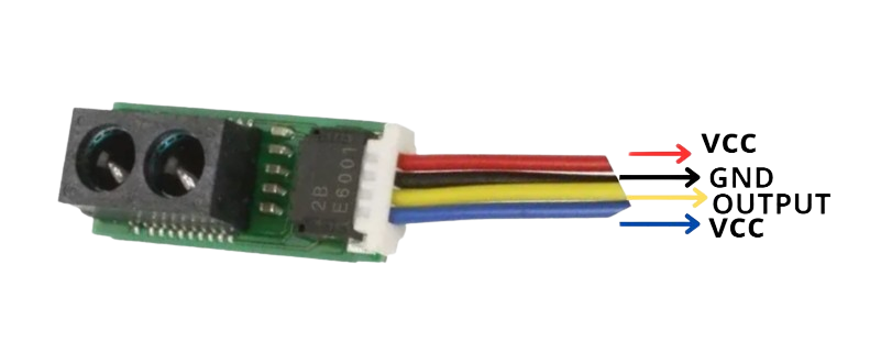
The Sharp sensor is connected as follows: the blue arrow can also be connected to a programming pin so that we can activate and deactivate it in operation; having it connected to VCC, the sensor will always be active.
CODE
const int sensorPin = A2;

void setup() {
  Serial.begin(115200);

  analogReadResolution(12);

  pinMode(sensorPin, INPUT);
  Serial.println("GP2Y0E02A Sensor ready...");
}

void loop() {
  // 1. Read raw value (0 - 4095)
  int rawValue = analogRead(sensorPin);

  // 2. Convert to Voltage (3.3V Reference)
  float voltage = rawValue * (3.3 / 4095.0);

  // 3. Calculate distance in cm using the datasheet slope
  // Using the linear equation: y = mx + b
  // Based on datasheet points: (0.55V, 50cm) and (2.2V, 4cm)
  float distanceCm = (voltage - 2.2) * (50.0 - 4.0) / (0.55 - 2.2) + 4.0;

  Serial.print("Voltage: ");
  Serial.print(voltage, 2);
  Serial.print("V | Distance: ");

  // 4. Range validation and output
  if (distanceCm > 55) {
    Serial.println("Fuera de rango (Lejos)");
  } else if (distanceCm < 3) {
    Serial.println("Fuera de rango (Cerca)");
  } else {
    Serial.print(distanceCm, 1);
    Serial.println(" cm");
  }

  delay(100);
}
RESULT
Although since I used the xiaoesp32 c6 and it only has three analog pins and one of the analog pins was already occupied by the capacitive button I didn't have any more left so I decided to make a board with an attiny that would be in charge of reading the value of the three sensors and then communicating it via I2C to my xiao.
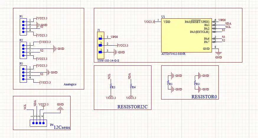
HOW TO PROGRAM THE ATTINY
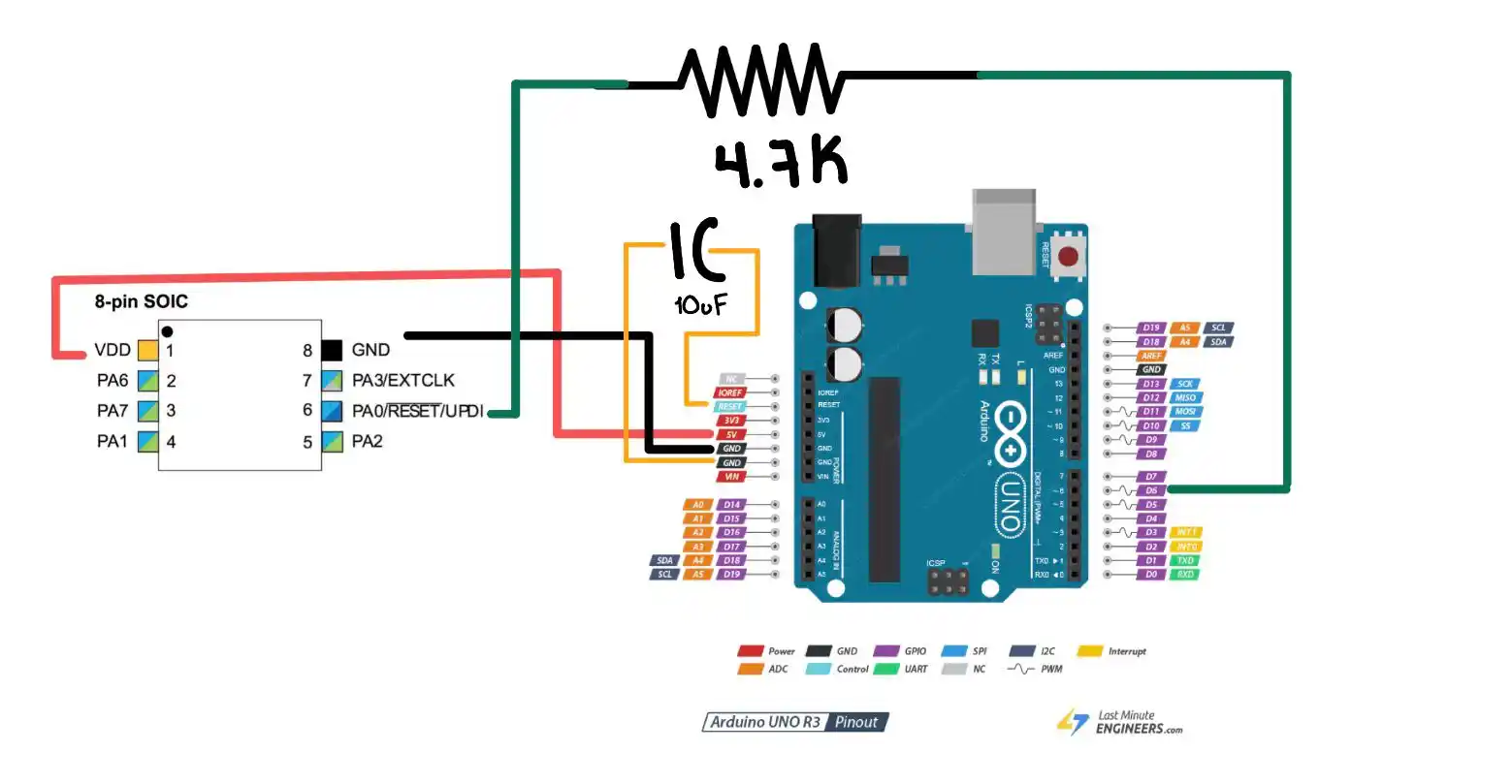
To program it it is important that we have these three pins to connect it to an Arduino uno: VCC, GND AND UPDI.
The steps to program the attiny are the following:
- We have to make the following connection with the Arduino uno
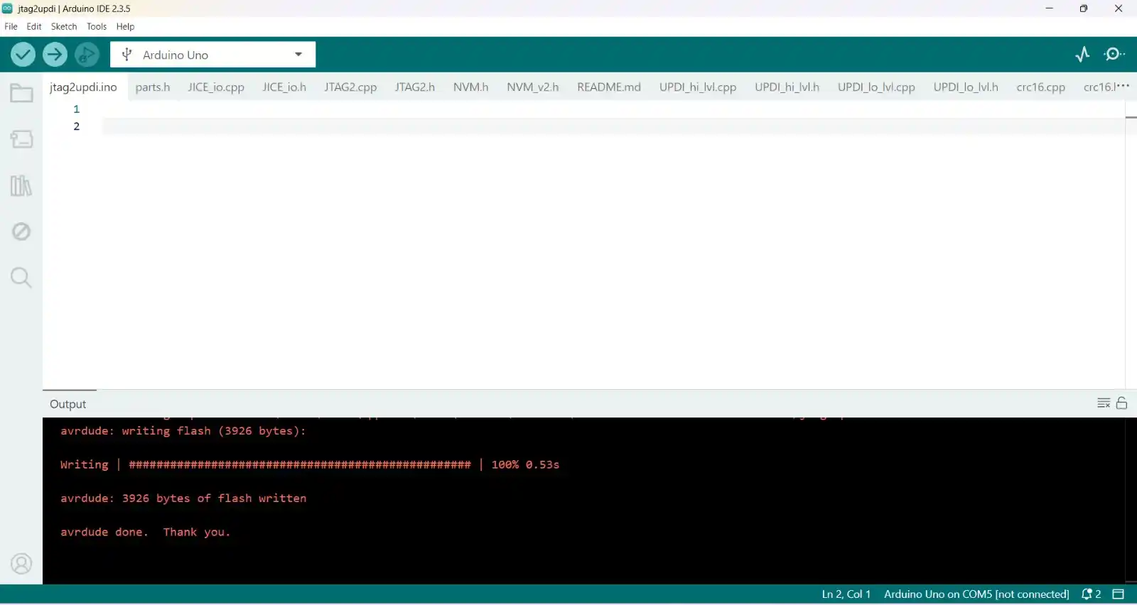
- Then we download from github the jtag2updi file that we have to unzip and open in Arduino.
- When we open it a file will appear that will have many files inside.
- We upload this file to our Arduino.
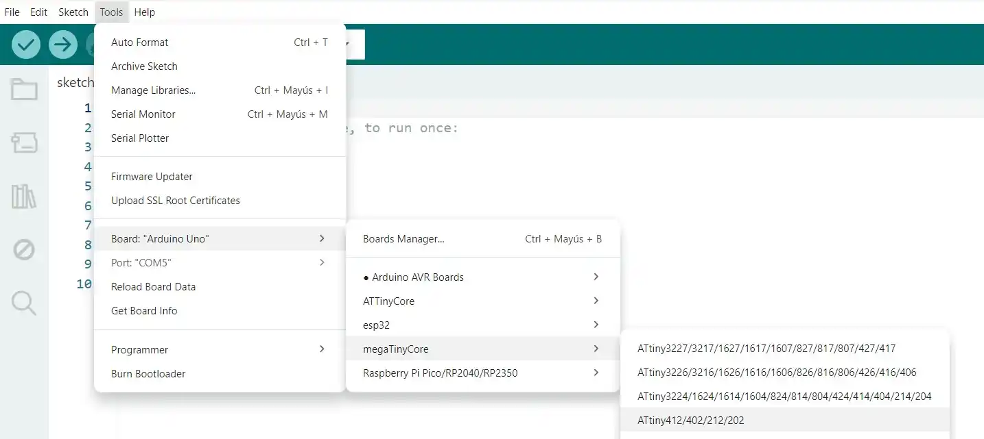
- Then in File> Preferences.
- In the "Additional Boards Manager URLs" section, we paste the following link: http://drazzy.com/package_drazzy.com_index.json
- In Tools > Board > Boards Manager, we search for “megaTinyCore” and install it.
- We go to Tools > Board > megaTinyCore and select "ATtiny412/402/212/202".
- In Tools > Programmer, we select "jtag2updi (megaTinyCore)".
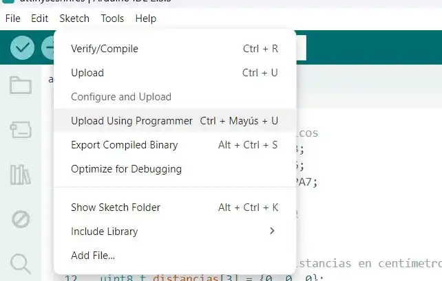
- To program it we go to Sketch> Upload Using Programmer
The code I uploaded to my attiny to detect the distance of our sensors was the following:
CODE
#include <Wire.h>
const int SLAVE_ADDRESS = 8;

void setup() {

  Serial.begin(115200);

  delay(2000);
  Serial.println("Iniciando maestro I2C en ESP32-C6...");

  Wire.begin();
}

void loop() {

  Wire.requestFrom(SLAVE_ADDRESS, 3);

  if (Wire.available() == 3) {

    uint8_t distIzq = Wire.read();
    uint8_t distDer = Wire.read();
    uint8_t distAtras = Wire.read();

    Serial.print("Izquierda: ");
    Serial.print(distIzq);
    Serial.print(" cm | Derecha: ");
    Serial.print(distDer);
    Serial.print(" cm | Atrás: ");
    Serial.print(distAtras);
    Serial.println(" cm");
  } else {
    Serial.println("Error: No se recibieron los datos del ATtiny412.");
  }


  delay(100);
}
OUTPUTS
For the outputs I have 2 which are the motors and the speaker, which are activated when the rtc detects that it is the same time that the user set in the interface, previously I tested the TB67H451AFNG for the output of my motors in WEEK 10.
MOTORS
I'm going to use small DC motors for when I escape, so do the following; for more information you can see my WEEK 10.
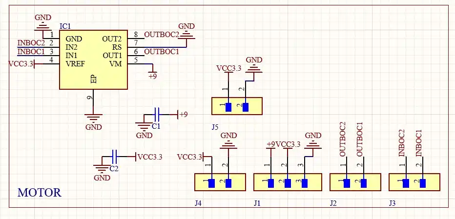
For my DC motor, I made the H-bridge using the TB67H451AFNG; this is the schematic of my H-bridge.
CODE
const int IN1 = 27; // PINS WHERE WE ARE GOING TO CONNECT THE MOTOR INPUTS
const int IN2 = 28;

void setup() {  // We configure both pins as OUTPUT
  pinMode(IN1, OUTPUT);
  pinMode(IN2, OUTPUT);
  detenerMotor();
}

void loop() {

  moverMotor(200); // We move the motor at a power of
  // in one direction for 2 seconds
  delay(2000);

  detenerMotor();// We stop the motor
  delay(1000);

  moverMotor(-200);// We start turning in the other direction
  delay(2000);

  detenerMotor();
  delay(1000);
}

void moverMotor(int velocidad) {
  if (velocidad > 0) {
    analogWrite(IN1, velocidad); // Function to make it turn to the right
    analogWrite(IN2, 0);// Sends IN2 to 0, so that one has no signal
  } else if (velocidad < 0) {
    analogWrite(IN1, 0); // Sets IN1 to 0, so that one has no signal
    analogWrite(IN2, abs(velocidad));// Function to make it turn to the left
  } else {
    detenerMotor();
  }
}

void detenerMotor() {
  analogWrite(IN1, 0);// Sets both IN to 0 so the motor does not turn
  analogWrite(IN2, 0);
}
RESULT
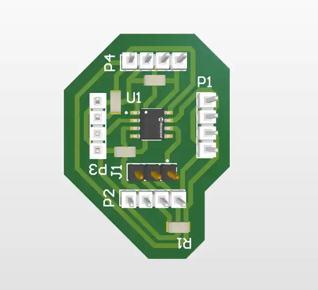
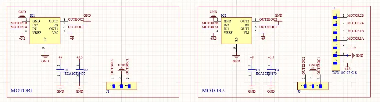
But for my project I took charge of making my board for two motors where my schematic is the following:
The code I tested for the operation of the H-bridge was the following:
// Motor 1 pins
const int motor1A = D10;
const int motor1B = D9;

// Motor 2 pins
const int motor2A = D8;
const int motor2B = D7;

// Rotation speed
int velocidad = 50;

void setup() {
  // Set motor pins as outputs
  pinMode(motor1A, OUTPUT);
  pinMode(motor1B, OUTPUT);
  pinMode(motor2A, OUTPUT);
  pinMode(motor2B, OUTPUT);
  detener();
}

void loop() {
  // Test cycle: forward, backward, left, right

  moverAdelante(velocidad);
  delay(2000);

  detener();
  delay(500);

  moverAtras(velocidad);
  delay(2000);

  detener();
  delay(500);

  girarIzquierda(velocidad);
  delay(1000);

  detener();
  delay(500);

  girarDerecha(velocidad);
  delay(1000);

  detener();
  delay(3000);
}


// Movement functions

// Function to move forward
void moverAdelante(int vel) {
  analogWrite(motor1A, vel);
  analogWrite(motor1B, 0);

  analogWrite(motor2A, vel);
  analogWrite(motor2B, 0);
}

// Function to move backward
void moverAtras(int vel) {
  analogWrite(motor1A, 0);
  analogWrite(motor1B, vel);

  analogWrite(motor2A, 0);
  analogWrite(motor2B, vel);
}

// Function to turn left
void girarIzquierda(int vel) {
  analogWrite(motor1A, 0);
  analogWrite(motor1B, vel);

  analogWrite(motor2A, vel);
  analogWrite(motor2B, 0);
}

// Function to turn right
void girarDerecha(int vel) {
  analogWrite(motor1A, vel);
  analogWrite(motor1B, 0);

  analogWrite(motor2A, 0);
  analogWrite(motor2B, vel);
} // ¡Aquí faltaba esta llave!

// Function to stop the motors
void detener() {
  analogWrite(motor1A, 0);
  analogWrite(motor1B, 0);
  analogWrite(motor2A, 0);
  analogWrite(motor2B, 0);
}
SPEAKER
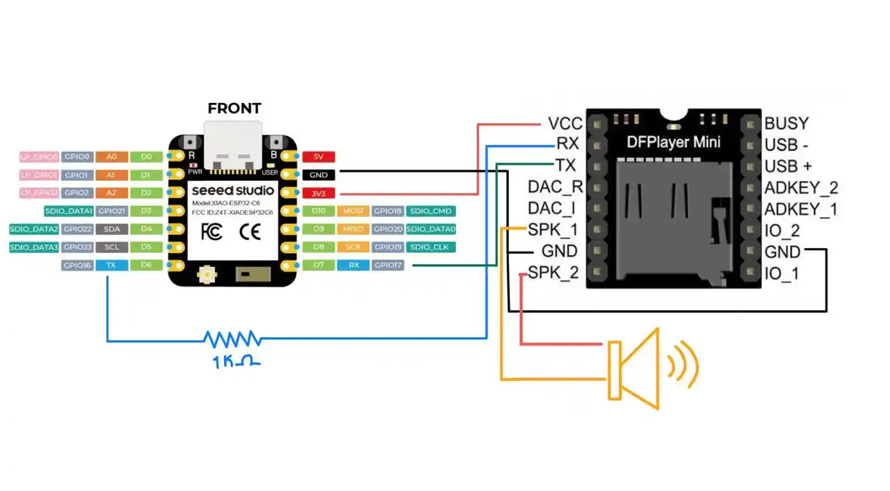
For the speaker to sound what I used was the DFplayer Mini MP3 Player module which I connected in the following way with my XIAO.
The steps you have to follow to play sounds are the following:
- Save the sounds you need in mp3.
- Use a micro sd and change the name of the files to 0001.mp3, 0002.mp3 and so on.
- Test the operation of the speaker with the following code
#include <Arduino.h>
#include <DFRobotDFPlayerMini.h>

HardwareSerial mySerial(1);
DFRobotDFPlayerMini myDFPlayer;

// Configure the maximum speaker volume, which will depend on the resistance of your speaker
const int VOLUMEN_MAXIMO = 15;

// Amount of time the audio will be played
unsigned long tiempoAnterior = 0;
const unsigned long INTERVALO = 15000; // 15 seconds

int pistaActual = 1;
bool secuenciaTerminada = false;

void setup() {
  Serial.begin(115200);
  mySerial.begin(9600, SERIAL_8N1, D7, D6);

  Serial.println("Starting audio system...");

  if (!myDFPlayer.begin(mySerial)) {
    Serial.println("Error: DFPlayer not detected.");
    while(true);
  }

  // Configure the volume
  myDFPlayer.volume(VOLUMEN_MAXIMO);

  myDFPlayer.play(pistaActual);

  tiempoAnterior = millis();
}

void loop() {
  if (!secuenciaTerminada) {

    unsigned long tiempoActual = millis();

    // Loop to play sound 1, sound 2 and sound 3
    if (tiempoActual - tiempoAnterior >= INTERVALO) {

      tiempoAnterior = tiempoActual;
      pistaActual++;

      if (pistaActual <= 3) {
        Serial.print("15 seconds have passed. Playing track ");
        Serial.println(pistaActual);
        myDFPlayer.play(pistaActual);
      } else {
        Serial.println("Track 3 reached. Sequence finished.");
        secuenciaTerminada = true;
      }
    }
  }
}
RESULT
SYSTEM INTEGRATION
To avoid having so many jumpers for what I did was align the connection pins of the H-bridge with the output pins of my main board where my xiao and my speaker module are located.
This is how the assembly of my boards turned out
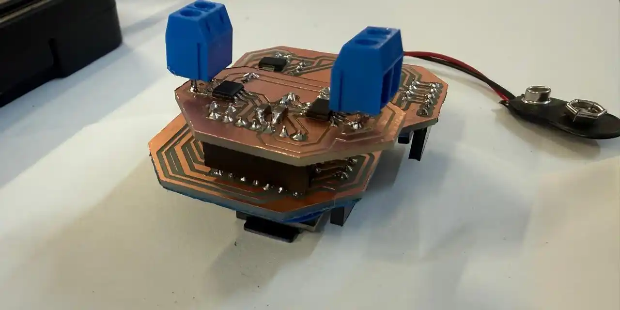
Since I couldn't avoid the cables for my distance sensors what I did was make a third board where the attiny is that is in charge of reading the sensors processes the values and communicates it with I2C to the main board where I tried to have the fewest cables possible which were VCC, GND,SCL AND SDA.
ASSEMBLY
I did some tests of how the structure moves
INTERFACE
To make the interface, I made it with HTML and it communicated using MQTT so that the user could set the alarm there at which the hamster should start ringing.
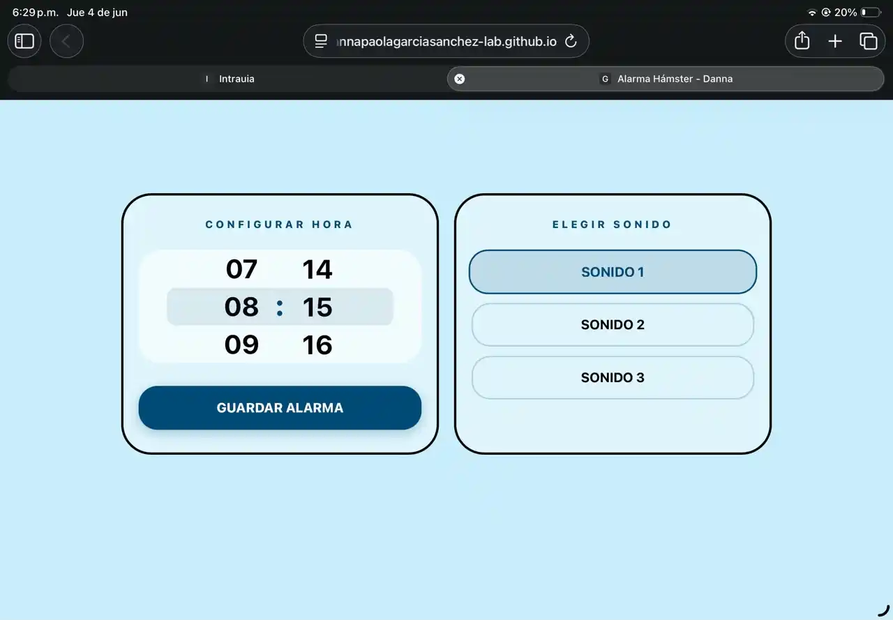
To make the carousel with that style on my page, I asked Gemini how to do it with the help of the following prompt:
“Make me the HTML code for a carousel with numbers in the style of the carousel that the iPhone has in its alarm app.”
CODE
1.- The <meta name="viewport"> tags serve to optimize the view on iPhone and prevent the user from zooming when touching the screen.
2.- The body uses Flexbox (display: flex) and justify-content: center to ensure the entire interface stays perfectly centered on the screen, regardless of the phone size.
<!DOCTYPE html>
<html lang="es">
<head>
    <meta charset="UTF-8" />
    <meta name="viewport" content="width=device-width, initial-scale=1.0, maximum-scale=1.0, user-scalable=no" />
    <meta name="apple-mobile-web-app-capable" content="yes" />
    <meta name="apple-mobile-web-app-status-bar-style" content="black-translucent" />
    <title>Alarma Hámster - Danna</title>

    <script src="https://unpkg.com/mqtt/dist/mqtt.min.js"></script>
    <style>
        :root {
            --bg: #C9EEFB;
            --strong-blue: #004B75;
            --text-main: #000000;
        }

        * {
            box-sizing: border-box;
            margin: 0;
            padding: 0;
            -webkit-tap-highlight-color: transparent;
        }

        body {
            font-family: -apple-system, BlinkMacSystemFont, 'Inter', sans-serif;
            background-color: var(--bg);
            color: var(--text-main);
            min-height: 100vh;
            display: flex;
            align-items: center;
            justify-content: center;
            padding: env(safe-area-inset-top) env(safe-area-inset-right) env(safe-area-inset-bottom) env(safe-area-inset-left);
        }
3.- scroll-snap-type: y mandatory; Forces the numbers to "snap" exactly in the center when scrolling.
4.- ::-webkit-scrollbar { display: none; } serves to hide the side scrollbar.
        .picker-wrapper {
            display: flex;
            align-items: center;
            justify-content: center;
            gap: 10px;
            background-color: rgba(255, 255, 255, 0.6);
            padding: 15px 25px;
            border-radius: 30px;
            position: relative;
            height: 150px;
            overflow: hidden;
            width: 100%;
        }

        .picker-wrapper::after {
            content: "";
            position: absolute;
            top: 50%; left: 10%; right: 10%;
            height: 50px;
            transform: translateY(-50%);
            background: rgba(0, 75, 117, 0.1);
            border-radius: 12px;
            pointer-events: none;
        }

        .picker-column {
            height: 150px;
            overflow-y: scroll;
            scroll-snap-type: y mandatory;
            scrollbar-width: none;
            width: 70px;
            -webkit-overflow-scrolling: touch;
        }

        .picker-column::-webkit-scrollbar { display: none; }

        .picker-item {
            height: 50px;
            display: flex;
            align-items: center;
            justify-content: center;
            font-size: 2.2rem;
            font-weight: 700;
            scroll-snap-align: center;
            scroll-snap-stop: always;
            color: var(--text-main);
        }
    </style>
</head>
5.- The dashboard-container divides the interface into two panels (.panel classes): one for the time and another for the sounds.
6.- The <div id="col-hours"> start empty because the numbers are included with JavaScript.
7.- The data-sonido="1" function serves to store the sound without the user seeing it in the button text, there are sound 1, sound 2, and sound 3.
<body>
    <div class="dashboard-container">
        <div class="panel">
            <div class="label">Configurar Hora</div>
            <div class="picker-wrapper">
                <div class="picker-column" id="col-hours"></div>
                <div class="colon">:</div>
                <div class="picker-column" id="col-minutes"></div>
            </div>
            <button id="btn-set-alarm" class="btn btn-inactive">Guardar Alarma</button>
        </div>

        <div class="panel">
            <div class="label">Elegir Sonido</div>
            <div class="sound-options">
                <button class="sound-btn selected" data-sonido="1">SONIDO 1</button>
                <button class="sound-btn" data-sonido="2">SONIDO 2</button>
                <button class="sound-btn" data-sonido="3">SONIDO 3</button>
            </div>
        </div>
    </div>
8.- mqtt.connect(broker) connects the web page directly to the HiveMQ public server via WebSockets.
9.- The initPicker function serves to print from 00 to 23 (hours) and from 00 to 59 (minutes).
10.- val = i < 10 ? '0' + i : i serves to add a leading zero if the number is a single digit.
    <script>
        const broker = "wss://broker.hivemq.com:8884/mqtt";
        const client = mqtt.connect(broker);
        const topicAlarm = "danna/alarma";

        client.on("connect", () => {
            console.log("Conectado al broker MQTT");
        });

        function initPicker(id, max) {
            const col = document.getElementById(id);
            col.innerHTML = '<div class="picker-spacer"></div>';
            for(let i = 0; i <= max; i++) {
                let val = i < 10 ? '0' + i : i;
                col.innerHTML += `<div class="picker-item">${val}</div>`;
            }
            col.innerHTML += '<div class="picker-spacer"></div>';
        }

        initPicker('col-hours', 23);
        initPicker('col-minutes', 59);
11.- soundButtons.forEach detects which sound button was pressed and saves its value (1, 2, or 3) in the sonidoSeleccionado variable.
12.- Math.round(hCol.scrollTop / 50) is the logic to know which time was chosen. It takes the scrolled pixels and divides them by 50 to get the exact index.
13.- client.publish packages the three data points and sends the final string to the MQTT topic (for example: "07:30-2") Which would be alarm 7:30 sound 2.
        let sonidoSeleccionado = "1";
        const soundButtons = document.querySelectorAll('.sound-btn');

        soundButtons.forEach(btn => {
            btn.addEventListener('click', () => {
                soundButtons.forEach(b => b.classList.remove('selected'));
                btn.classList.add('selected');
                sonidoSeleccionado = btn.getAttribute('data-sonido');
            });
        });

        const btnSetAlarm = document.getElementById("btn-set-alarm");

        btnSetAlarm.addEventListener("click", () => {
            const hCol = document.getElementById('col-hours');
            const mCol = document.getElementById('col-minutes');

            const hIndex = Math.round(hCol.scrollTop / 50);
            const mIndex = Math.round(mCol.scrollTop / 50);

            const hours = hIndex < 10 ? '0' + hIndex : hIndex;
            const minutes = mIndex < 10 ? '0' + mIndex : mIndex;

            const alarmPayload = `${hours}:${minutes}-${sonidoSeleccionado}`;

            client.publish(topicAlarm, alarmPayload);
            console.log("Alarma publicada:", alarmPayload);

            btnSetAlarm.classList.replace("btn-inactive", "btn-active");
            btnSetAlarm.innerText = "¡Enviado!";

            setTimeout(() => {
                btnSetAlarm.classList.replace("btn-active", "btn-inactive");
                btnSetAlarm.innerText = "Guardar Alarma";
            }, 2000);
        });
    </script>
</body>
</html>
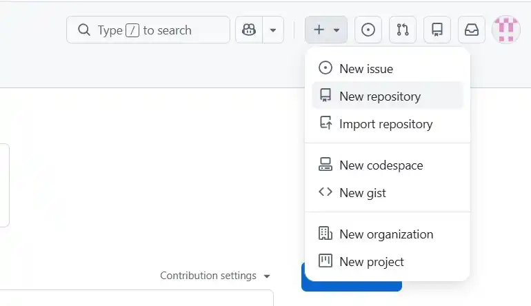
To be able to open my application on my phone, I uploaded it to GitHub with the following steps:
- Save the HTML code and name it index.html
- Log in to your GitHub account.
- In the upper right corner, click the + icon and select New repository.
- Give it a name and mark it as public.
- Click the green Create repository button.
- Look for the option that says "...or uploading an existing file".
- Drag your index.html file there and then click the green Commit changes button.
- On the page of your new repository, go to the Settings tab.
- In the left side menu, look for the section that says Pages.
- Where it says "Branch", you will see a drop-down menu that says "None". Change it by selecting main.
- Click Save.
- Copy the link that appears and open it wherever you want.
FINAL RESULT
In the end, I only took care of joining all the small things that I had previously tested into a final code that was:
- Interface where the user sets the time.
- RTC that is responsible for knowing the time.
- Motors for movement.
- Sensors to know where to go.
- Speaker to place the sound.
- Capacitive button to stop the movement and the sound.
CODE
#include <WiFi.h>
#include <PubSubClient.h>
#include <DFRobotDFPlayerMini.h>
#include <HardwareSerial.h>
#include <Wire.h>

const char* ssid = "INFINITUM0B53_2.4";
const char* password = "fTUXCH4CMR";

const char* mqtt_server = "broker.hivemq.com";
const char* mqtt_topic = "danna/alarma";
WiFiClient espClient;
PubSubClient client(espClient);

HardwareSerial mySerial(1);
DFRobotDFPlayerMini myDFPlayer;
const int VOLUMEN_MAXIMO = 15;

const int analog_pin = A2;
const int tx_pin = D3;

const int motor1A = D10;
const int motor1B = D9;
const int motor2A = D0;
const int motor2B = D1;
int velocidad = 50;

const int ATTINY_ADDRESS = 8;
const int DS3231_ADDR = 0x68;

struct Alarma {
  int hora;
  int minuto;
  int sonido;
  bool activa;
};

const int MAX_ALARMAS = 10;
Alarma misAlarmas[MAX_ALARMAS];

bool alarmaSonando = false;
int minutoUltimaAlarma = -1;
unsigned long tiempoUltimoEscaneo = 0;

long tx_rx() {
  int read_high;
  int read_low;
  int diff;
  long sum = 0;
  int N_samples = 100;

  for (int i = 0; i < N_samples; i++) {
    digitalWrite(tx_pin, HIGH);
    read_high = analogRead(analog_pin);
    delayMicroseconds(100);

    digitalWrite(tx_pin, LOW);
    read_low = analogRead(analog_pin);

    diff = read_high - read_low;
    sum += diff;
  }
  return sum;
}

void moverAdelante(int vel) {
  analogWrite(motor1A, vel); analogWrite(motor1B, 0);
  analogWrite(motor2A, vel); analogWrite(motor2B, 0);
}

void moverAtras(int vel) {
  analogWrite(motor1A, 0); analogWrite(motor1B, vel);
  analogWrite(motor2A, 0); analogWrite(motor2B, vel);
}

void girarIzquierda(int vel) {
  analogWrite(motor1A, 0); analogWrite(motor1B, vel);
  analogWrite(motor2A, vel); analogWrite(motor2B, 0);
}

void girarDerecha(int vel) {
  analogWrite(motor1A, vel); analogWrite(motor1B, 0);
  analogWrite(motor2A, 0); analogWrite(motor2B, vel);
}

void detener() {
  analogWrite(motor1A, 0); analogWrite(motor1B, 0);
  analogWrite(motor2A, 0); analogWrite(motor2B, 0);
}

uint8_t bcdToDec(uint8_t val) {
  return ((val / 16 * 10) + (val % 16));
}

void obtenerHoraRTC(int &hora, int &minuto, int &segundo) {
  Wire.beginTransmission(DS3231_ADDR);
  Wire.write(0x00);
  Wire.endTransmission();

  Wire.requestFrom(DS3231_ADDR, 3);
  if (Wire.available() >= 3) {
    segundo = bcdToDec(Wire.read());
    minuto = bcdToDec(Wire.read());
    hora = bcdToDec(Wire.read() & 0x3F);
  }
}

void setup_wifi() {
  Serial.print("Conectando a ");
  Serial.println(ssid);
  WiFi.begin(ssid, password);
  while (WiFi.status() != WL_CONNECTED) { delay(500); Serial.print("."); }
  Serial.println("\nWiFi conectado.");
}

void reconnect() {
  while (!client.connected()) {
    Serial.print("Intentando conexión MQTT...");
    String clientId = "ESP32C6Client-" + String(random(0xffff), HEX);
    if (client.connect(clientId.c_str())) {
      Serial.println("conectado");
      client.subscribe(mqtt_topic);
    } else {
      delay(5000);
    }
  }
}

void callback(char* topic, byte* payload, unsigned int length) {
  String mensaje = "";
  for (int i = 0; i < length; i++) mensaje += (char)payload[i];

  if (mensaje.length() >= 7) {
    int h = mensaje.substring(0, 2).toInt();
    int m = mensaje.substring(3, 5).toInt();
    int s = mensaje.substring(6, 7).toInt();

    bool actualizada = false;
    for (int i = 0; i < MAX_ALARMAS; i++) {
      if (misAlarmas[i].activa && misAlarmas[i].hora == h && misAlarmas[i].minuto == m) {
        misAlarmas[i].sonido = s;
        actualizada = true;
        break;
      }
    }

    if (!actualizada) {
      for (int i = 0; i < MAX_ALARMAS; i++) {
        if (!misAlarmas[i].activa) {
          misAlarmas[i].hora = h; misAlarmas[i].minuto = m;
          misAlarmas[i].sonido = s; misAlarmas[i].activa = true;
          break;
        }
      }
    }
  }
}

void rutinaHamster() {
  if (millis() - tiempoUltimoEscaneo > 5000) {
    Serial.println("Escaneando entorno...");

    girarDerecha(velocidad);
    delay(1500);
    detener();
    delay(100);

    Wire.requestFrom(ATTINY_ADDRESS, 3);
    if (Wire.available() == 3) {
      uint8_t distIzq = Wire.read();
      uint8_t distDer = Wire.read();
      uint8_t distAtras = Wire.read();

      if (distIzq >= distDer && distIzq >= distAtras) {
        girarIzquierda(velocidad);
        delay(500);
      }
      else if (distDer >= distIzq && distDer >= distAtras) {
        girarDerecha(velocidad);
        delay(500);
      }
      else {
        moverAtras(velocidad);
        delay(1000);
      }
    }
    tiempoUltimoEscaneo = millis();
  }

  moverAdelante(velocidad);
}

void setup() {
  Serial.begin(115200);

  pinMode(tx_pin, OUTPUT);

  pinMode(motor1A, OUTPUT); pinMode(motor1B, OUTPUT);
  pinMode(motor2A, OUTPUT); pinMode(motor2B, OUTPUT);
  detener();

  for (int i = 0; i < MAX_ALARMAS; i++) misAlarmas[i].activa = false;

  Wire.begin();
  setup_wifi();
  client.setServer(mqtt_server, 1883);
  client.setCallback(callback);

  mySerial.begin(9600, SERIAL_8N1, D7, D6);
  if (!myDFPlayer.begin(mySerial)) {
    Serial.println("Error en DFPlayer.");
  } else {
    myDFPlayer.volume(VOLUMEN_MAXIMO);
  }
}

void loop() {
  if (!client.connected()) reconnect();
  client.loop();

  int horaActual = 0, minutoActual = 0, segundoActual = 0;
  obtenerHoraRTC(horaActual, minutoActual, segundoActual);

  if (!alarmaSonando) {
    for (int i = 0; i < MAX_ALARMAS; i++) {
      if (misAlarmas[i].activa && horaActual == misAlarmas[i].hora && minutoActual == misAlarmas[i].minuto) {
        if (minutoActual != minutoUltimaAlarma) {
          Serial.println("¡DESPIERTA!");
          myDFPlayer.loop(misAlarmas[i].sonido);
          alarmaSonando = true;
          tiempoUltimoEscaneo = millis();
          break;
        }
      }
    }
  }

  if (alarmaSonando) {
    long valorRAW = tx_rx();

    if (valorRAW >= 6500) {
      Serial.print("Hamster atrapado. Valor RAW: ");
      Serial.println(valorRAW);

      myDFPlayer.pause();
      detener();
      alarmaSonando = false;
      minutoUltimaAlarma = minutoActual;
      delay(500);
    } else {
      rutinaHamster();
    }
  }

  if (minutoActual != minutoUltimaAlarma && !alarmaSonando) {
    minutoUltimaAlarma = -1;
  }
}
PACKAGING
For the packaging, I thought that if the product were to be launched in the future, it could be packaged as if it were in a crib, considering it's a device to wake you up and looks cute. What I did was get a wooden crib and paint it, and then I used a vinyl cutter to make the letters C.H.A.S.E. To learn how to use the vinyl cutter, you can see my WEEK03.