For this week's assignment, I had to implement an output; in my case, I used a DC motor, an OLED screen, and a servomotor.
I used the board I made in week 8 but since some tracks broke because I dropped it, I had to make it again, although I removed the heart shape.
1. OUTPUTS
Digital outputs can be in two states: HIGH or LOW, where HIGH is high voltage like 3.3 or 5,
which are the typical outputs of microcontrollers, or low voltage; both help to turn devices like LEDs on and off.
Digital outputs also serve to control other devices; to learn more information, you can see the GROUP PAGE.
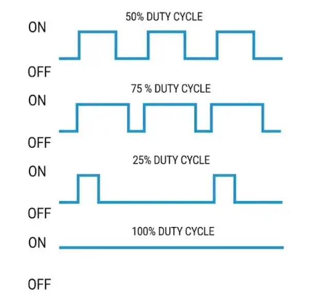
There are also PWM outputs, which work by rapidly alternating between on (5V/3.3V) and off (0V). An important concept of PWM outputs is the Duty Cycle.
Duty Cycle: It is the percentage of time that the signal remains high (HIGH) during a complete cycle.
If you have a 100% duty cycle, the signal is always HIGH (constant 5V).
If you have a 50% duty cycle, the signal spends half the time on and half off, which gives an average voltage of 2.5V.
For this week, I used 3 outputs: a DC motor, an OLED, and a servo motor.
Energy Consumption
To calculate the energy consumption of my three outputs, I used the formula P = V * I, considering the voltage they were going to be powered at and the current they need to function.
DC motor
Current = 2A
Voltage = 5V
P = 5 * 2 P = 10 W
Servo Motor
Current = 0.5A
Voltage = 5V
P = 5 * 0.5 P = 2.5 W
OLED
Current = 0.08A
Voltage = 5V
P = 5 * 0.08 P = 0.4 W
2. DEVICES
DC MOTOR
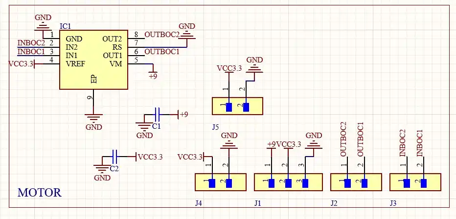
For my DC motor, I made the H-bridge using the TB67H451AFNG; this is the schematic of my H-bridge.
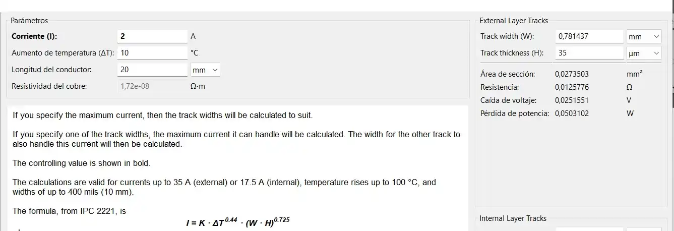
To know the size my tracks should have, I
calculated how much current would pass through the tracks when using the motor; I used the KiCad track calculator where
I set the current to approximately 2A, in case my motor jams or something like that. With these parameters, I got a width of 0.8 mm.
The two inputs of the H-bridge connect to the outputs of my board from week 8 to be able to indicate direction; it is important that common grounds are connected."
CODE
const int IN1 = 27; // PINS WHERE WE ARE GOING TO CONNECT THE MOTOR INPUTS
const int IN2 = 28;

void setup() {  // We configure both pins as OUTPUT
  pinMode(IN1, OUTPUT);
  pinMode(IN2, OUTPUT);
  detenerMotor();
}

void loop() {

  moverMotor(200); // We move the motor at a power of
  // in one direction for 2 seconds
  delay(2000);

  detenerMotor();// We stop the motor
  delay(1000);

  moverMotor(-200);// We start turning in the other direction
  delay(2000);

  detenerMotor();
  delay(1000);
}

void moverMotor(int velocidad) {
  if (velocidad > 0) {
    analogWrite(IN1, velocidad); // Function to make it turn to the right
    analogWrite(IN2, 0);// Sends IN2 to 0, so that one has no signal
  } else if (velocidad < 0) {
    analogWrite(IN1, 0); // Sets IN1 to 0, so that one has no signal
    analogWrite(IN2, abs(velocidad));// Function to make it turn to the left
  } else {
    detenerMotor();
  }
}

void detenerMotor() {
  analogWrite(IN1, 0);// Sets both IN to 0 so the motor does not turn
  analogWrite(IN2, 0);
}
RESULT
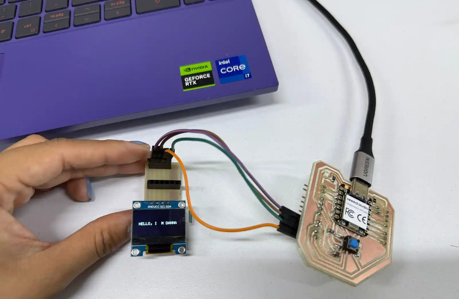
OLED
I also used the OLED, but the libraries I tried to use with Arduino
didn't work with my Xiao RP2350 because the libraries used the first I2C channel, which were
the pins found underneath my XIAO, D13 and D14; so, since I didn't use these pins on my board, I switched to Visual to program it there.
The display OLED only has four pins to allow the display management.
VCC: Power Pin.
GND: Connect to microcontroller's ground.
SCL: I2C communication clock.
SDA: I2C Data line.
I2C is a two-wire serial communication protocol using a serial data line (SDA) and a serial clock line (SCL). The protocol supports multiple target devices on a communication bus and can also support multiple controllers that send and receive commands and data.
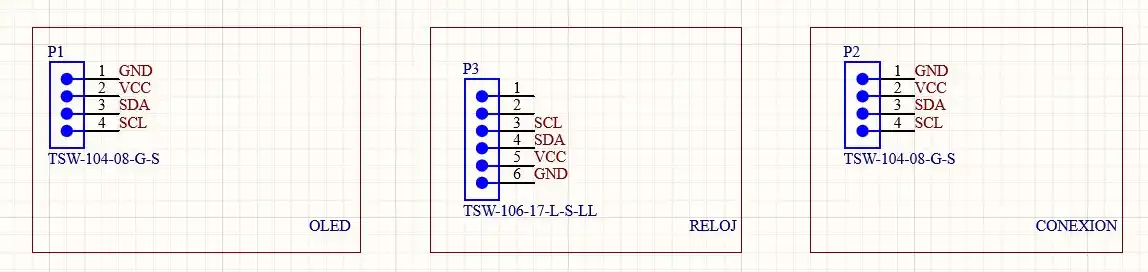
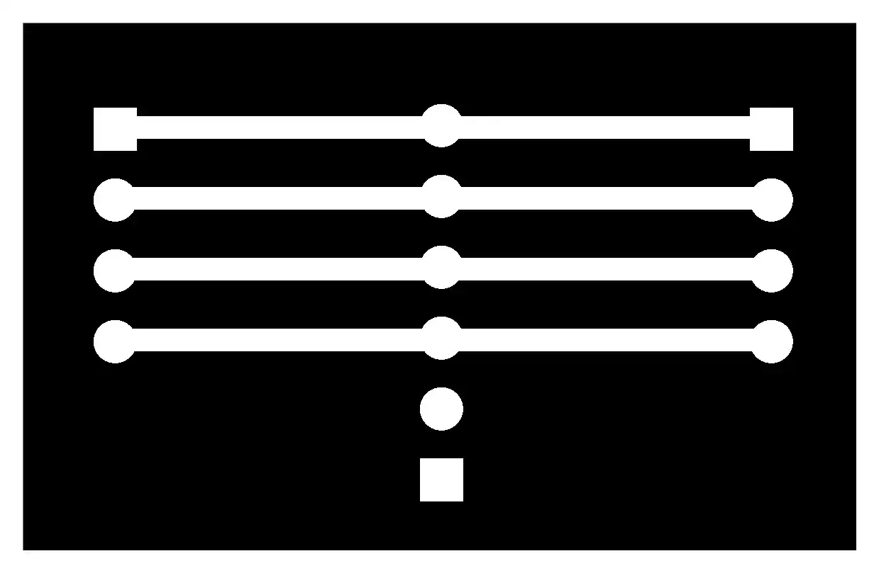
To make it easier to connect my OLED, I made a small board with the power and I2C pins to then connect two I2C devices to that board; this is the schematic and the fabrication files can be found in the files section.
VISUAL STUDIO CODE
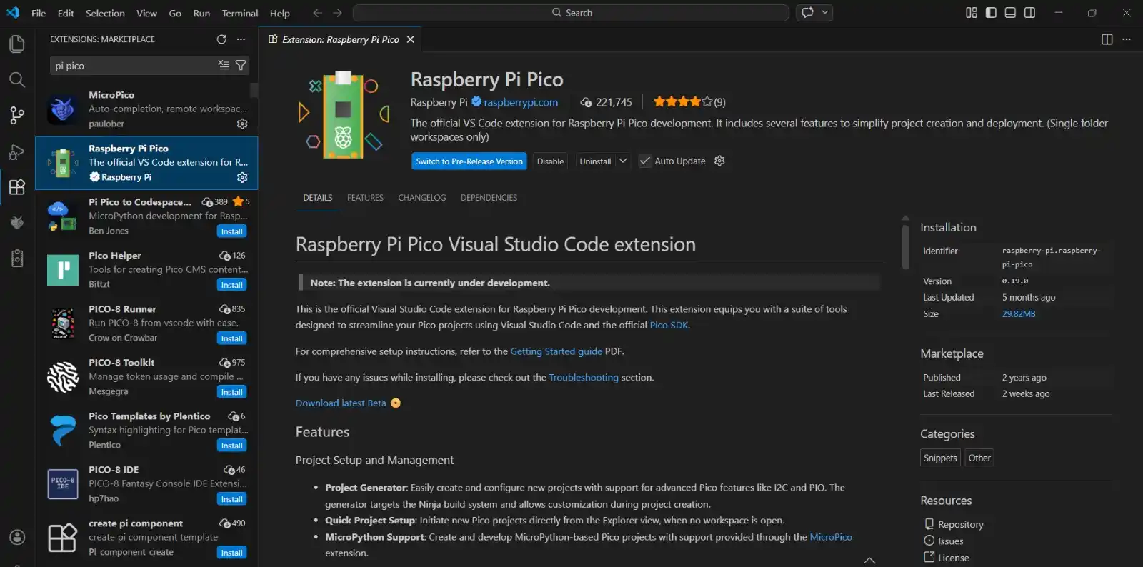
In Visual Studio > libraries, we download the Raspberry Pi Pico library.
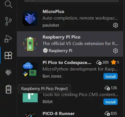
Now these new options will appear in the menu on the left; we press the Raspberry Pi Pico Project option.
Ready, we can start programming in Visual.
With Visual I could already turn on my OLED, but to write something I had to make functions to turn on each pixel depending on the letter, so I installed a library that could help me.
Click on 'Download raw file' for the following three files: ssd1306.c, ssd1306.h, and font.h
Then we have to add them to our project's folder.
In the CMakeLists.txt file, we add the following line "ssd1306.c" in the add_executable section.
CODE
#include <stdio.h>
#include "pico/stdlib.h"
#include "hardware/i2c.h"

// We include the external library
#include "ssd1306.h"

#define I2C_PORT i2c1
#define I2C_SDA  6
#define I2C_SCL  7

int main() {
    stdio_init_all();

    // 1. Initialize the I2C pins of your board (this stays the same)
    i2c_init(I2C_PORT, 400 * 1000);
    gpio_set_function(I2C_SDA, GPIO_FUNC_I2C);
    gpio_set_function(I2C_SCL, GPIO_FUNC_I2C);
    gpio_pull_up(I2C_SDA);
    gpio_pull_up(I2C_SCL);

    //Configure the screen using the library
    ssd1306_t disp;
    disp.external_vcc = false;
    // We initialize: object, width, height, I2C address, I2C port
    ssd1306_init(&disp, 128, 64, 0x3C, I2C_PORT);

    //Clear the screen in case there was garbage
    ssd1306_clear(&disp);

    //(object, X, Y, text_size, message)

    ssd1306_draw_string(&disp, 10, 30, 1, "HELLO, I´M DANNA"); // Size 1

    //Send the data so they are shown on the OLED
    ssd1306_show(&disp);

    while (true) {
        sleep_ms(1000);
    }
}
RESULT
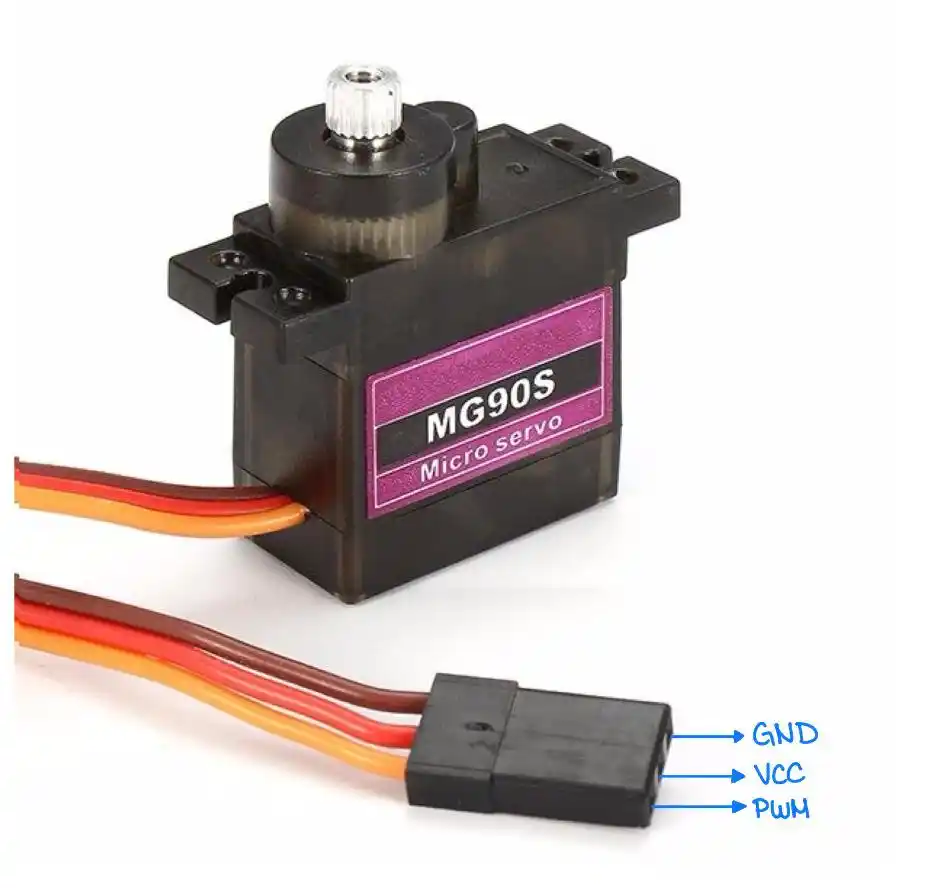
SERVO MOTOR
The servo operates off of a 4.0V to 7.2V power supply and it can draw as much as 0.5A.
Servomotor control relies on the transmission of electrical signals of adjustable duration, a technique known as pulse-width modulation (PWM),
which is transmitted through the control line. This pulse defines the shaft's position; thus, depending on the signal's duration, the rotor will move to the required angle.
For proper operation, the device requires a constant signal with a 20-millisecond (ms) interval between each pulse. The length of these pulses dictates the motor's final range of motion.
To test its operation, I made a code so that it would change position every time a button is pressed.
CODE
// Button and servo pins
const int botonPin = 0;
const int servoPin = 3;

int contadorToques = 0;  // Variable to store the number of button
// presses that have occurred
bool ultimoEstadoBoton = HIGH; // Boolean variable to
// remember the last state of the button.

void setup() {
  // Configuration of my motor and my button
  pinMode(botonPin, INPUT_PULLUP);
  pinMode(servoPin, OUTPUT);
  Serial.begin(115200);
}

void loop() {

  // Read the state of the button
  int lecturaBoton = digitalRead(botonPin);

  if (lecturaBoton == LOW && ultimoEstadoBoton == HIGH) {
    delay(50);
    contadorToques++; // We add 1 to the click counter to move the servo

    if (contadorToques > 3) {
      contadorToques = 1; // If 3 touches are reached, it returns to touch 1
    }
  }

  ultimoEstadoBoton = lecturaBoton; // Update the memory


  int tiempoAlto = 1000; // We start by setting the high time to 1ms, which would be
  //0 degrees

  switch (contadorToques) {
    case 1:
      tiempoAlto = 1000;  // Mode 1: 0 degrees (1 ms pulse)
      break;

    case 2:
      tiempoAlto = 1500;  // Mode 2: 90 degrees (1.5 ms pulse)
      break;

    case 3:
      tiempoAlto = 2000;  // Mode 3: 180 degrees (2 ms pulse)
      break;

    default:
      tiempoAlto = 1000;  // Initial position before pressing the button
      break;
  }

// We generate the PWM
  digitalWrite(servoPin, HIGH);
  delayMicroseconds(tiempoAlto);           // Time that the pulse is high

  digitalWrite(servoPin, LOW);
  delayMicroseconds(20000 - tiempoAlto);   // Low time to complete the 20ms cycle
}
RESULT
FILES
Here you can download the source files created during this week: