8. Electronics Production
For this week's assignment, I decided to design and manufacture a functional embedded microcontroller system. The main objective was to transition from digital design to a physical printed circuit board (PCB) using the precision manufacturing tools at the FabLab.
Materials and Tools
The base material used was a single-sided copper phenolic board. For the milling process in the precision machine, I used the following bits:
- 45° V-bit: For trace routing.
- 0.8 mm mill bit: For through-holes.
- 1 mm end mill: For cutting the board outline.
To correctly configure the feed rates and spindle speeds according to the material and the bit, you can consult the technical details on our GROUP PAGE.
1. Files and Workflow
The process for creating my board was as follows:
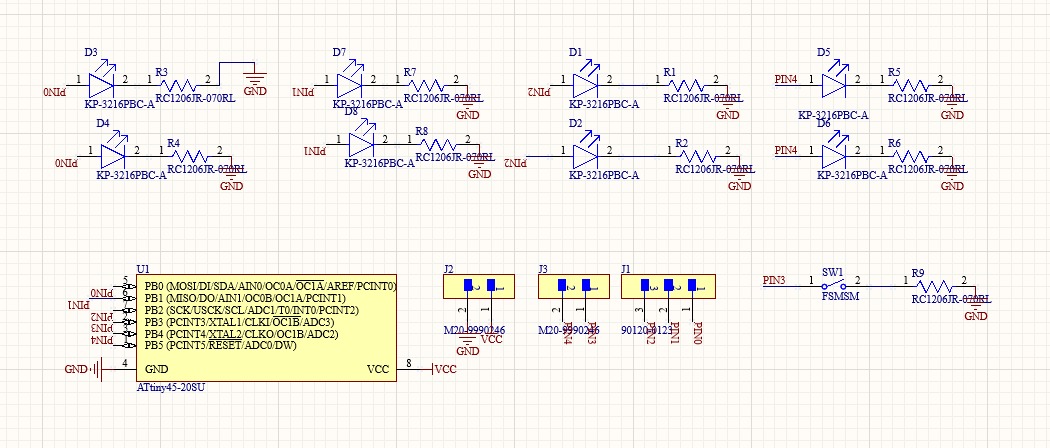
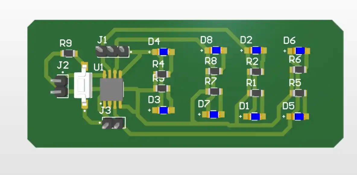
- Design my PCB: In my case, I used the heart board design I created in week 6.
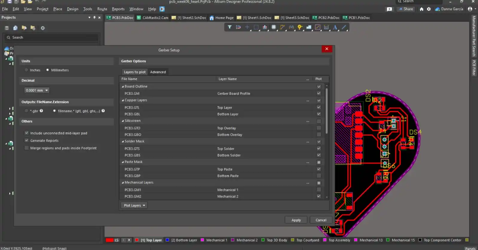
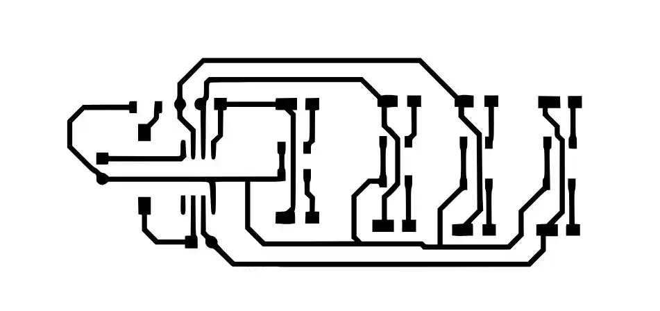
- In Altium: Go to File > Fabrication Outputs > Gerber Files. The options I enabled were Copper Layers, Silkscreen, Solder Mask, Paste Mask, and in Mechanical Layers, select the layer where you have your board edge; this Gerber is used for the traces and the border. This is what the Gerber file looks like:
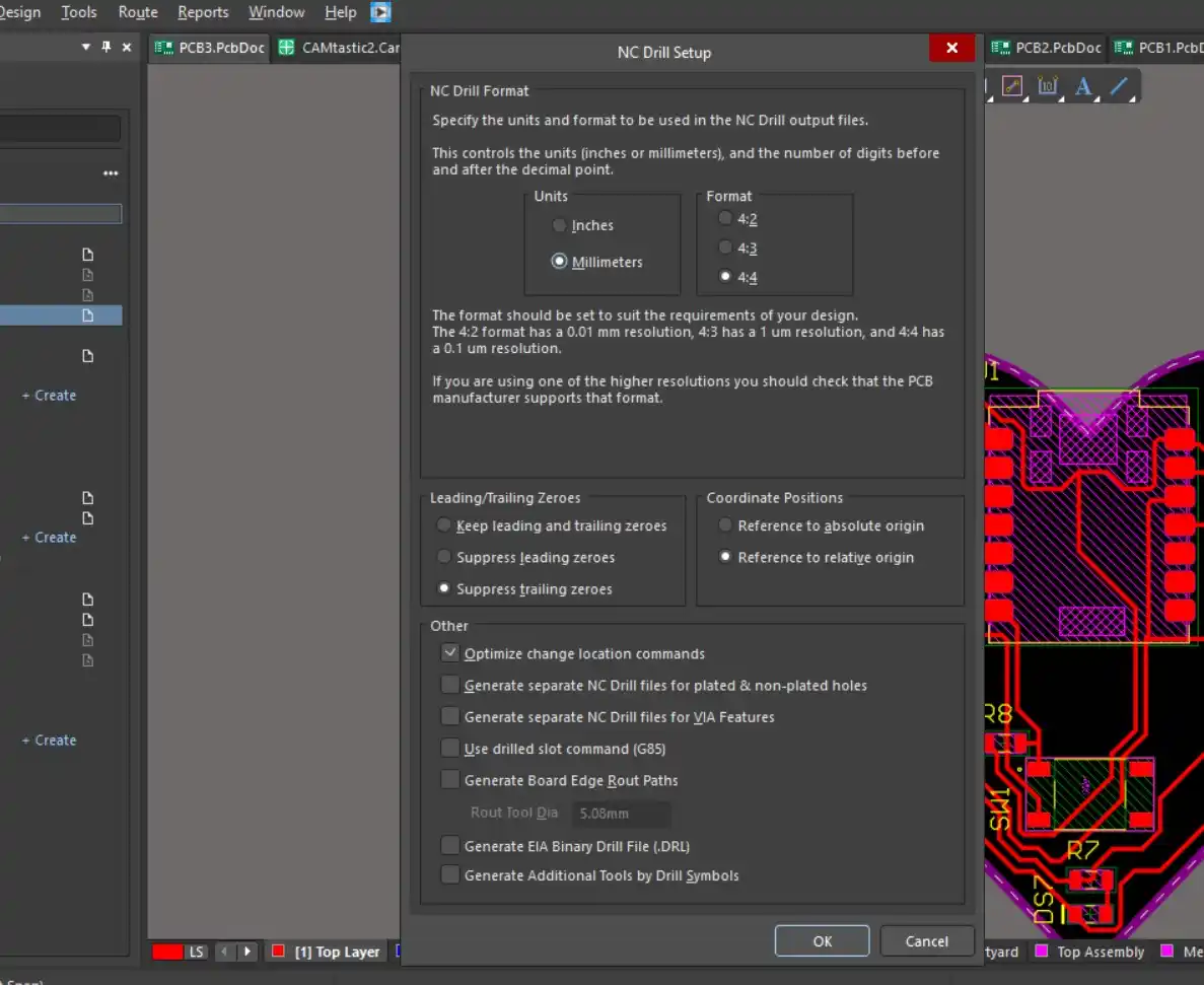
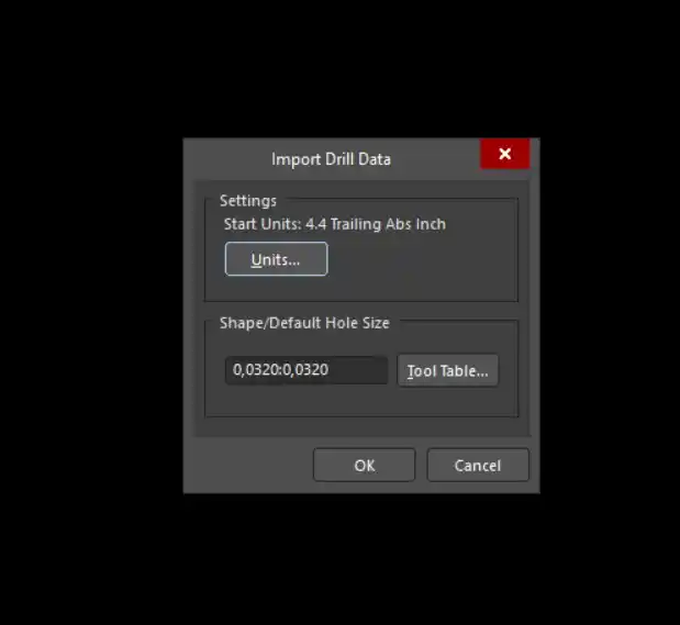
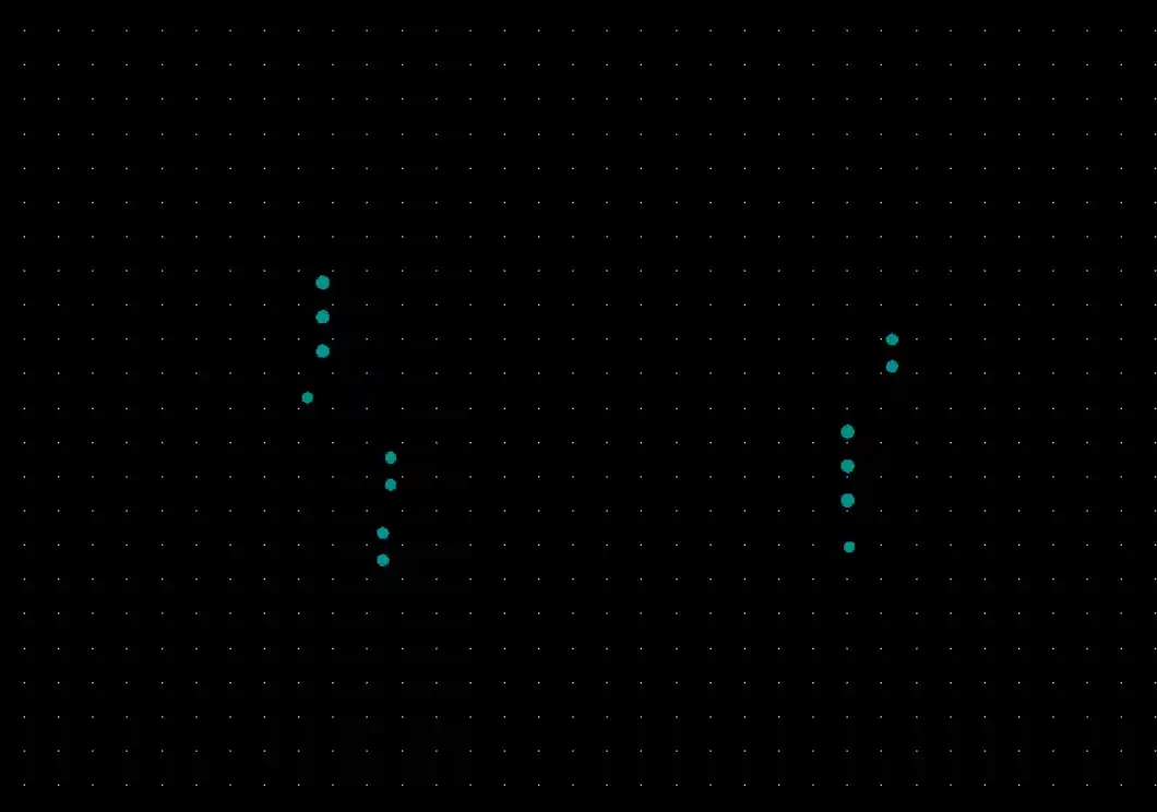
- For the holes: Go to File > Fabrication Outputs > NC Drill Format. We set the measurements in which our PCB is located. This is what our holes file looks like.
- In our Altium project folder: a Project Outputs folder is created, and there we find our Gerber files and NC Drill.
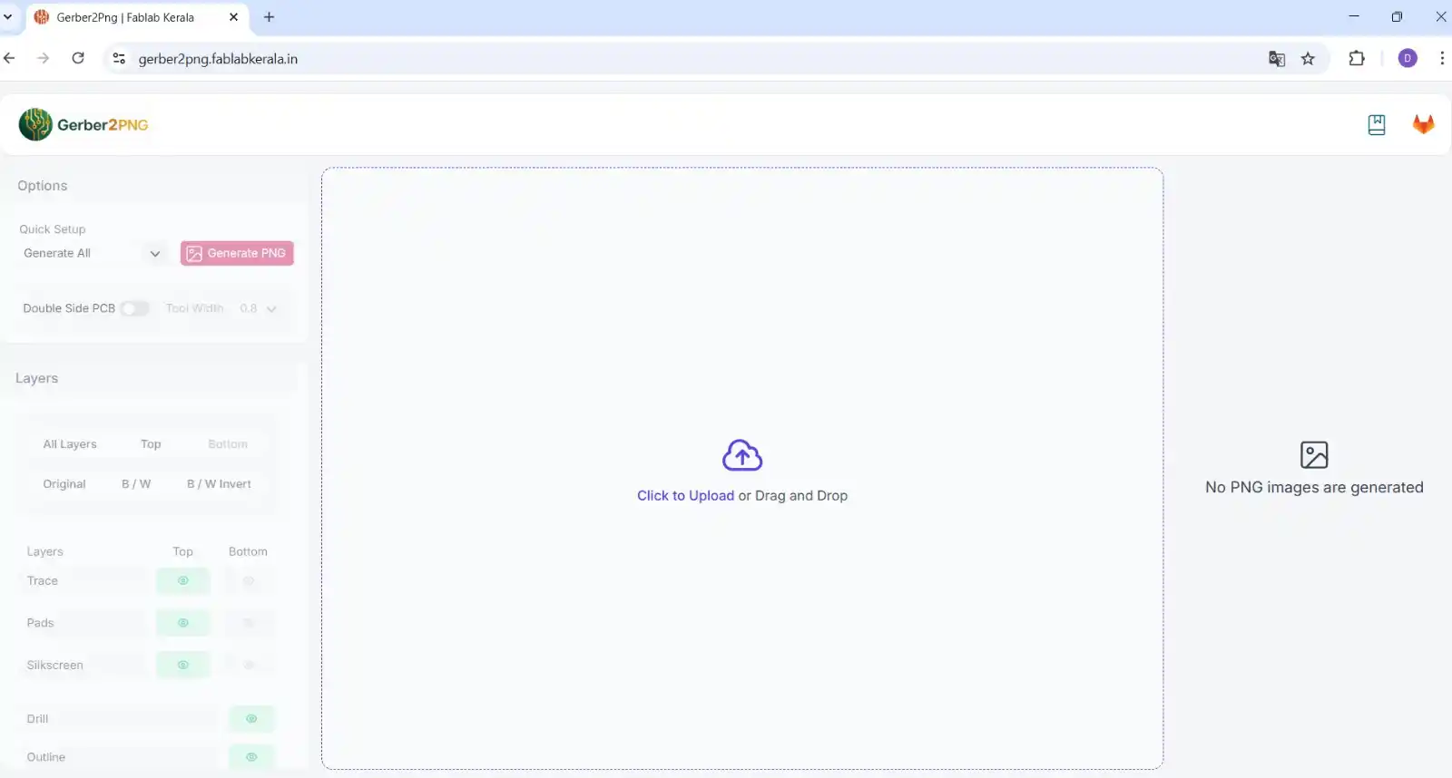
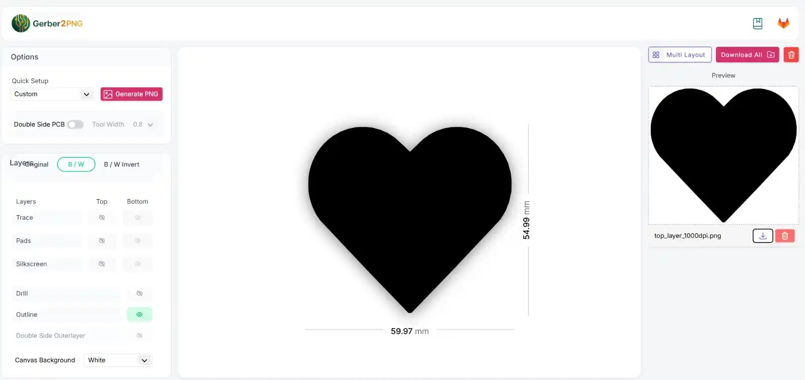
- With the help of the following page: I converted the Gerber files to PNG.
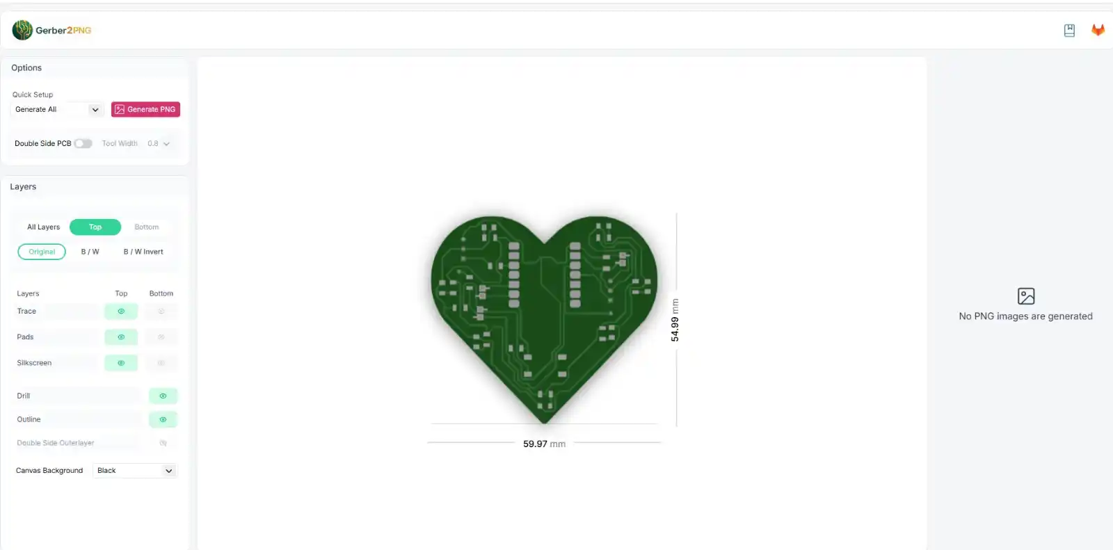
- In "click to upload": we add all the files that are in fabrication outputs. This is how my board looks in the program.
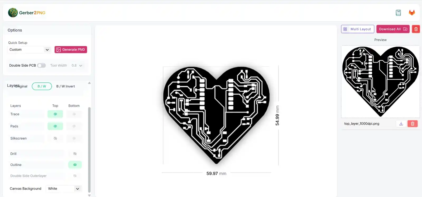
- For the traces: we select the B/W, trace, silkscreen, and outline options; in canvas background, we select white and then click the "generate PNG" button.
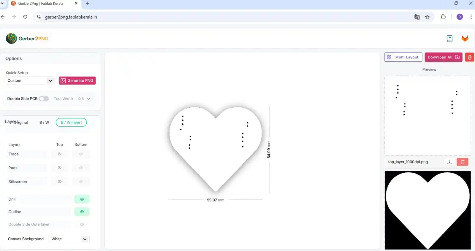
- For the holes: we select the Drill and B/W Invert options, and in canvas background White and click "generate PNG."
- For the outline: we select the Outline and B/W Invert options, canvas background black, and click "generate PNG."

2. MODS
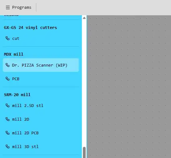
For the files for the Roland, which is the machine we have at FabLab Puebla, we use the following page called "mods."
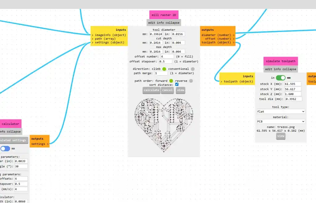
- Select the mill 2D PCB option for the SRM-20 mill.
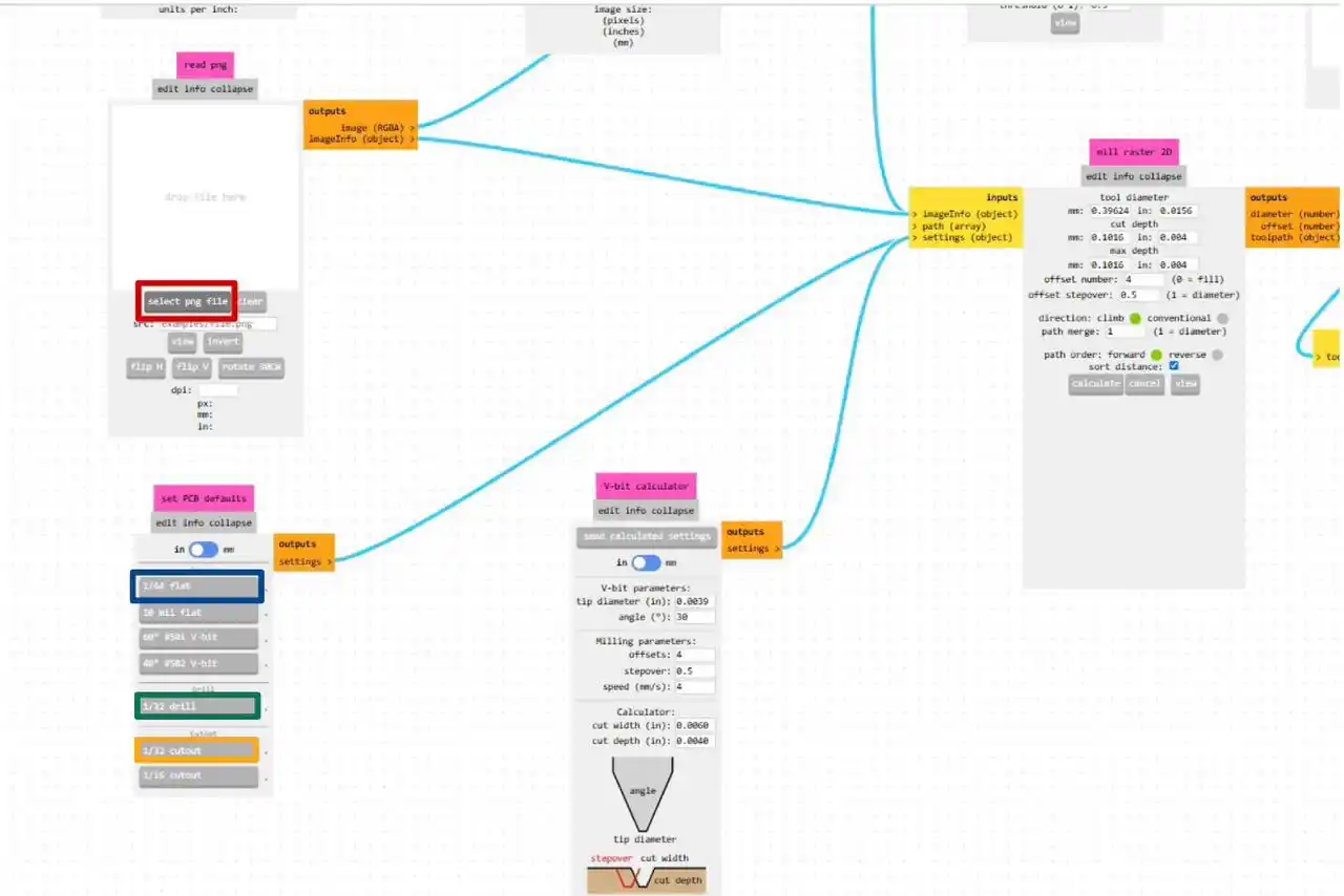
- Click the select png file option and select the image we obtained from Gerber to PNG.
- For the traces we select the blue option, for the holes the green option, and for the outline the orange option.
- I left the tool specifications that had come up for me.
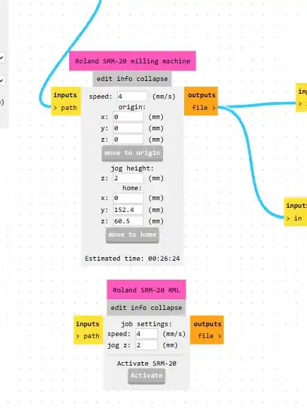
- In the following menu, it is very important that in the origin we put 0 in all axes, and in speed, I changed the trace speed to 4, the holes to 0.2, and the edge cut to 2.
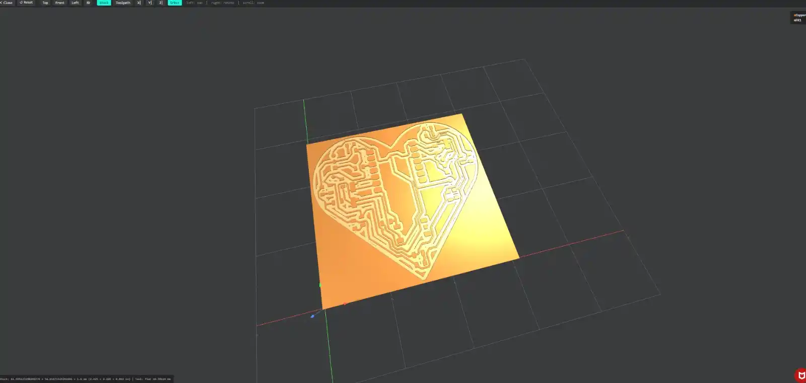
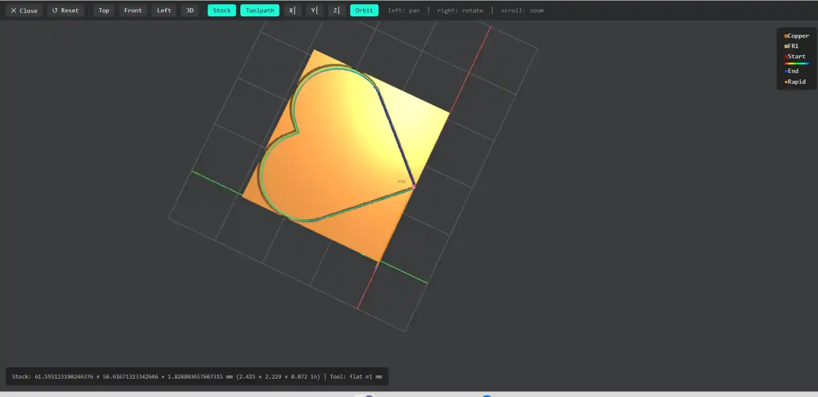
- Afterward, we click the calculate button, and this is what the simulation of the board cut looks like.
- To save our files, we have to activate the output files option.
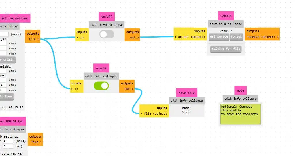
3. Fabrication
To operate the Roland, we use the VPanel program.
- With the cursors, we move the axes.
- In the orange option, we select the step speed.
- The blue option is used to set the origin point.
- The green option is used to move to the origin.
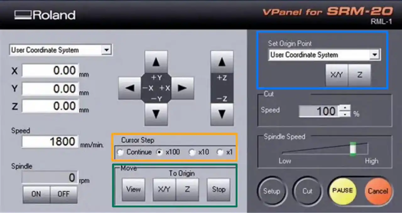
To cut, we click the purple option and select the file we obtained from mods, then click "output." It is very important that we calibrate the tool in the machine well; additionally, between each file, we must change the tool depending on what we are going to do: traces, holes, and edge cut.
4. Fabrication result
To make our PCB on the Roland at Fab Lab Puebla, we need a sacrifice bed that you can find in my downloadable files.
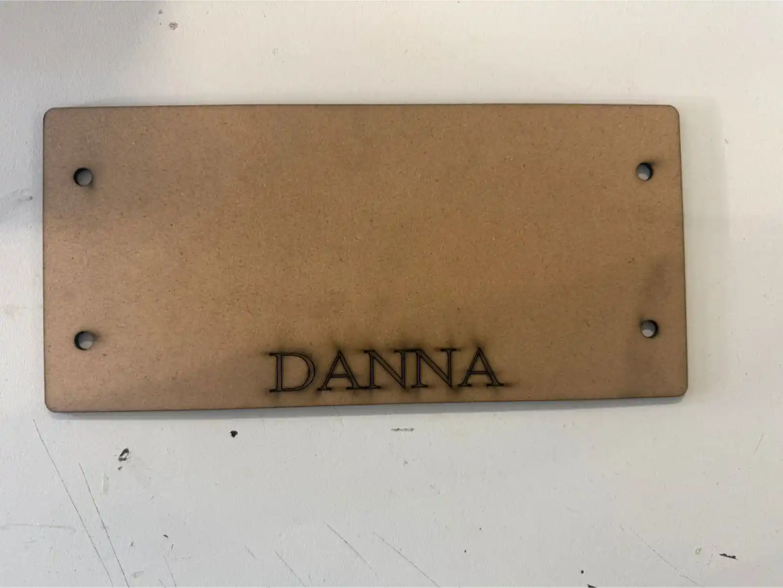
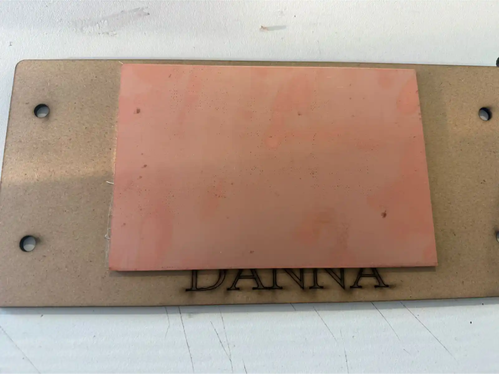
Then we have to stick the phenolic board to the sacrifice bed with double-sided tape.
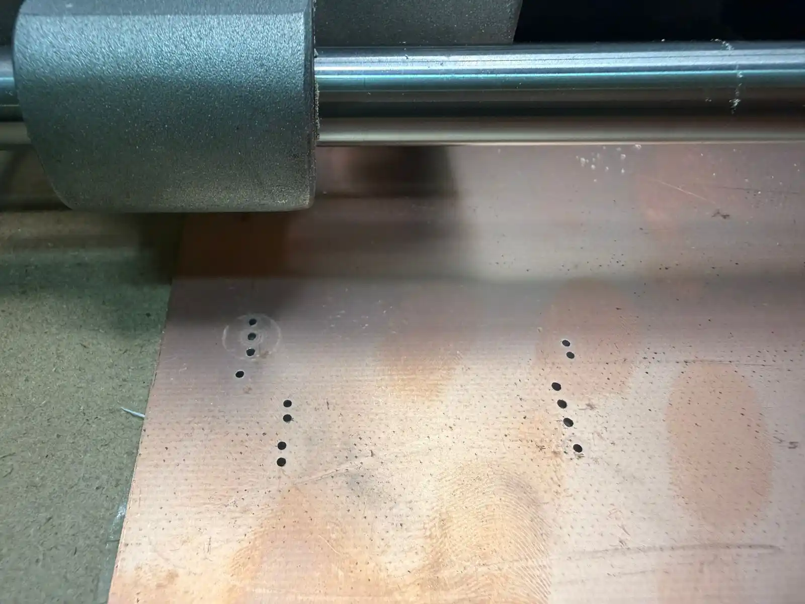
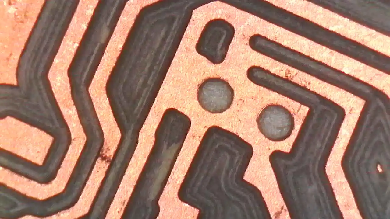
The first file I placed was the one for the holes and that is how it finished.
Afterwards I put the file for the traces and finally the one for the border.
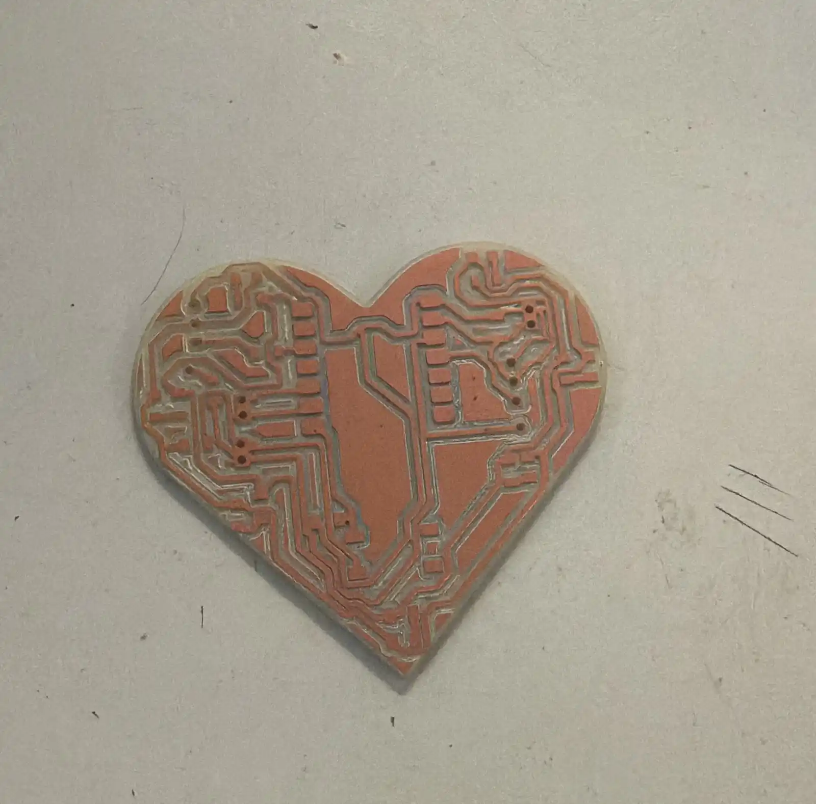
5. Final result
The result of my PCB after the Roland is like this:
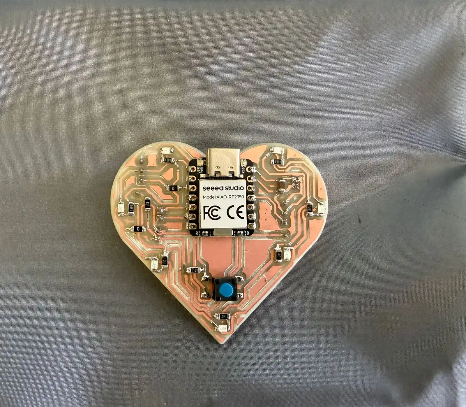
I started soldering with the following materials:
- 7 red 1206 LEDs
- 1 button
- 7 resistors of 1200 ohms
- 3 resistors of 0 ohms
- 1 resistor of 10 k
- 1 capacitor of 10 microF
- Pins
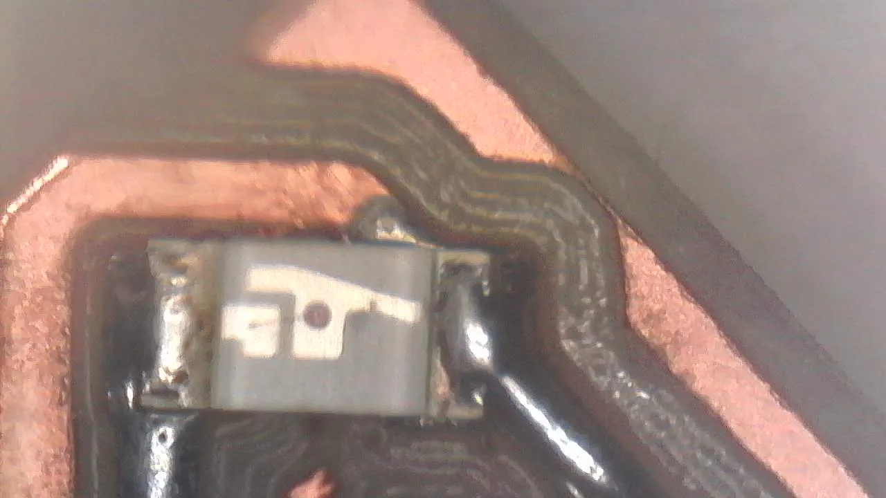
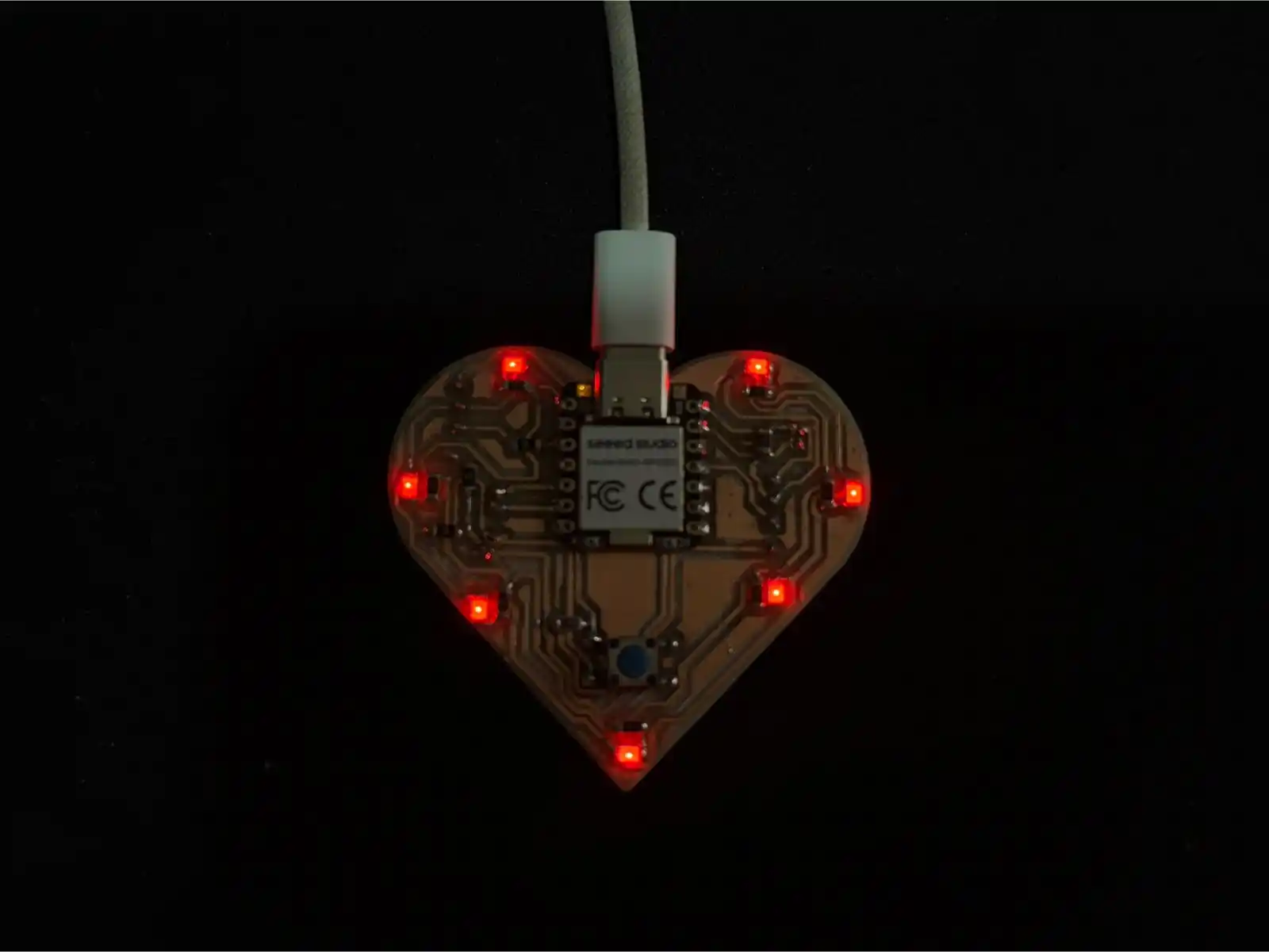
This is how my soldered PCB ended up.
To test it, I used the following code that makes my LEDs turn on with the button.
const int botonPin = 0;
const int ledPin = 26;


int contadorToques = 0;
bool ultimoEstadoBoton = HIGH;

void setup() {
  pinMode(botonPin, INPUT_PULLUP);
  pinMode(ledPin, OUTPUT);
  Serial.begin(115200);
}

void loop() {
  int lecturaBoton = digitalRead(botonPin);


  if (lecturaBoton == LOW && ultimoEstadoBoton == HIGH) {
    delay(50);
    contadorToques++;


    if (contadorToques > 3) {
      contadorToques = 1;
    }

    Serial.print("Modo actual: ");
    Serial.println(contadorToques);
  }

  ultimoEstadoBoton = lecturaBoton;


  switch (contadorToques) {
    case 1:

      digitalWrite(ledPin, HIGH);
      break;

    case 2:

      digitalWrite(ledPin, HIGH);
      delay(200);
      digitalWrite(ledPin, LOW);
      delay(200);
      break;

    case 3:
      digitalWrite(ledPin, LOW);
      break;

    default:
      digitalWrite(ledPin, LOW);
      break;
  }
}
6. Flexible PCB
- First, I made my PCB with an ATtiny and some LEDs; what I used was copper tape and the vinyl cutter.
- I exported my file as a PDF and opened it in Inkscape to be able to save it as an SVG.
- This is how the file looks after passing it to Inkscape.
- On the vinyl cutter mat, we place the material we are going to use and stick a piece of copper tape on top; then we follow the steps I used in week 3.
- Pressure: 3
- Speed: 2
- This is how my PCB finished.
The parameters I set for the vinyl cutter were:
const int filauno = 0;
const int filados = 1;
const int filatres = 2;
const int filacuatro = 4;

const int boton = 3;

int estadoBoton = 0;
int ultimoEstadoBoton = 0;
int estadoActual = 0;

void setup() {

  pinMode(filauno, OUTPUT);
  pinMode(filados, OUTPUT);
  pinMode(filatres, OUTPUT);
  pinMode(filacuatro, OUTPUT);


  pinMode(boton, INPUT_PULLUP);


  digitalWrite(filauno, LOW);
  digitalWrite(filados, LOW);
  digitalWrite(filatres, LOW);
  digitalWrite(filacuatro, LOW);
}

void loop() {
  // Leer el estado del botón
  estadoBoton = digitalRead(boton);


  if (estadoBoton == LOW && ultimoEstadoBoton == HIGH) {

    estadoActual++;
    if (estadoActual > 2) {
      estadoActual = 0;
    }

    delay(50);
  }


  ultimoEstadoBoton = estadoBoton;


  switch (estadoActual) {
    case 0:

      digitalWrite(filauno, LOW);
      digitalWrite(filados, LOW);
      digitalWrite(filatres, LOW);
      digitalWrite(filacuatro, LOW);
      break;

    case 1:

      digitalWrite(filauno, HIGH);
      digitalWrite(filatres, HIGH);
      digitalWrite(filados, LOW);
      digitalWrite(filacuatro, LOW);
      break;

    case 2:

      digitalWrite(filauno, LOW);
      digitalWrite(filatres, LOW);
      digitalWrite(filados, HIGH);
      digitalWrite(filacuatro, HIGH);
      break;
  }
}