3. Computer Controlled Cutting
This week's assignment is to design a parametric kit and then cut it using the laser cutter. We will also be using a vinyl cutter.
For more information about materials and uses of the laser cutter as well as more parameters that are used, go to our GROUP PAGE .
I'm going to explain a little bit about what I did this week:
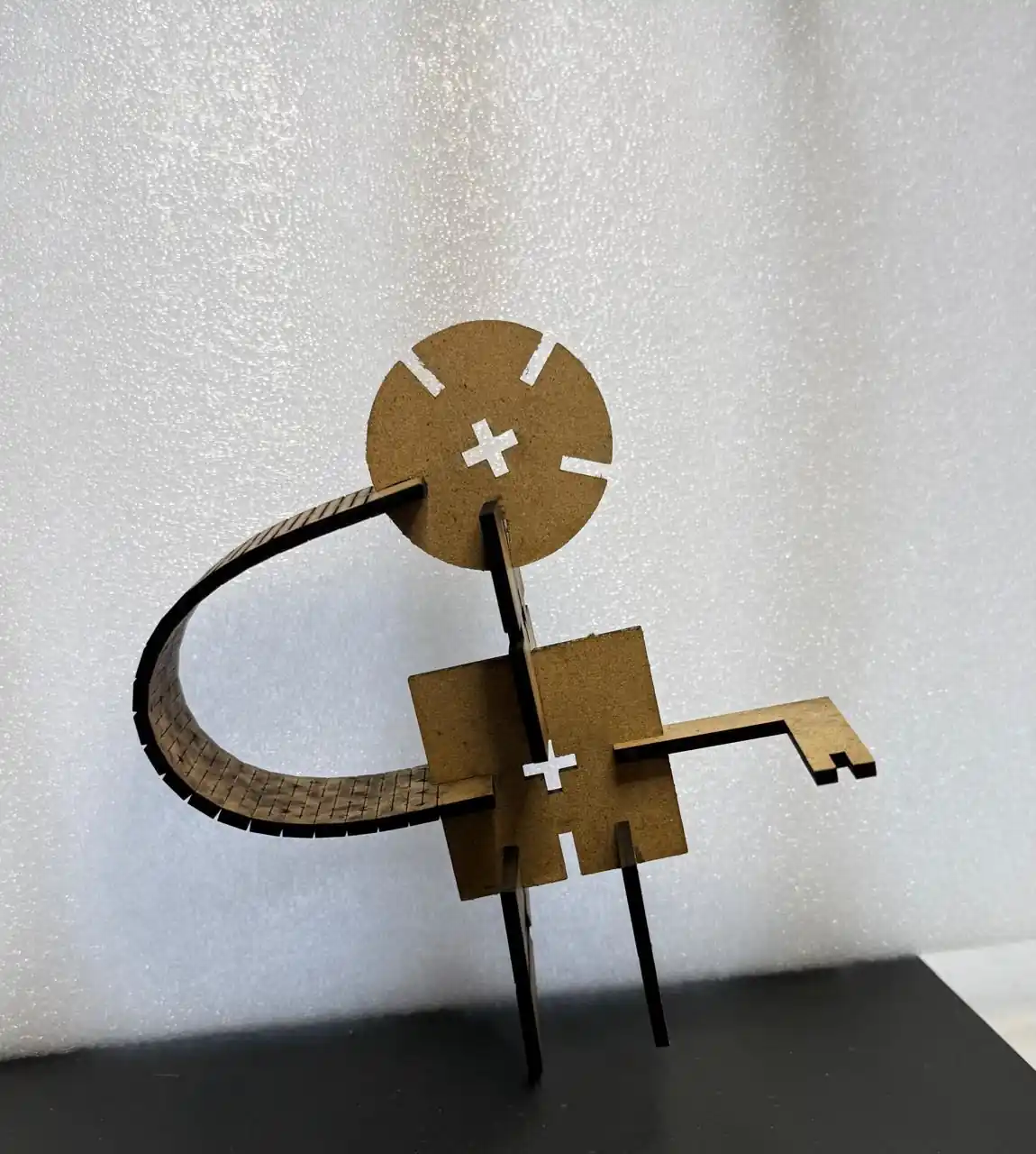
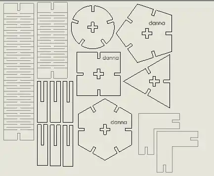
1. My kit
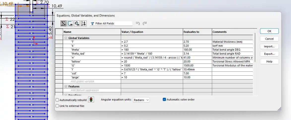
Equations in SolidWorks
This is the most important tool for parameterizing parts. The steps to use it are as follows:
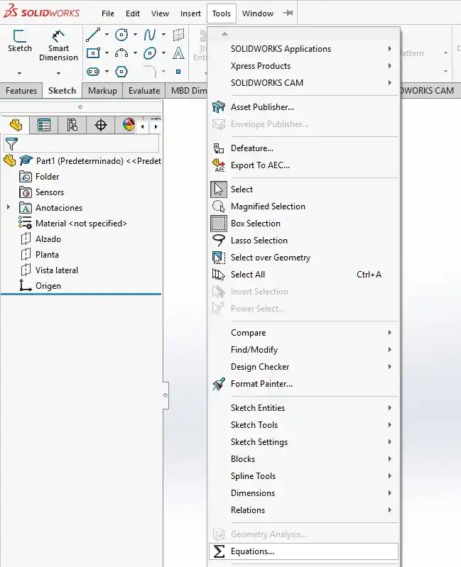
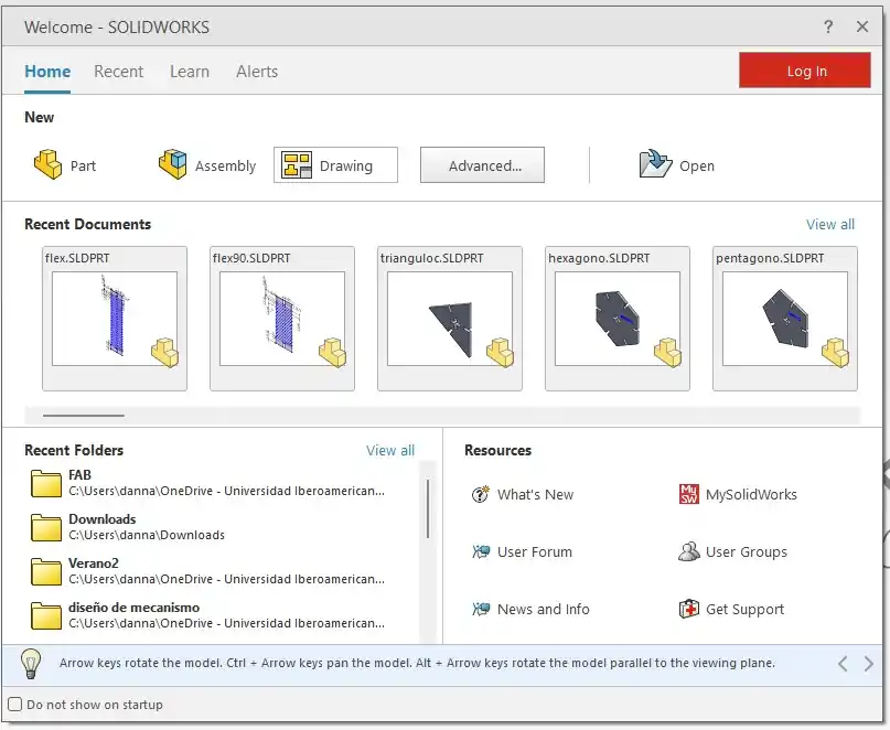
- Open SolidWorks and create a new part, then go to the Tools menu.
- In the Tools menu, look for the Equations option located near the bottom.
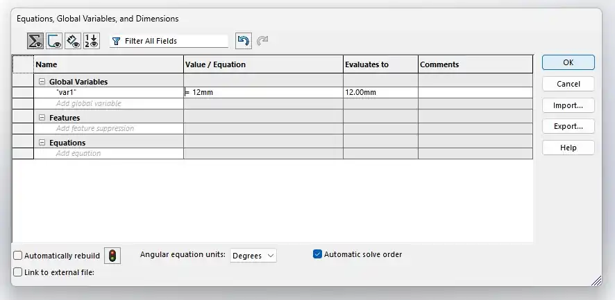
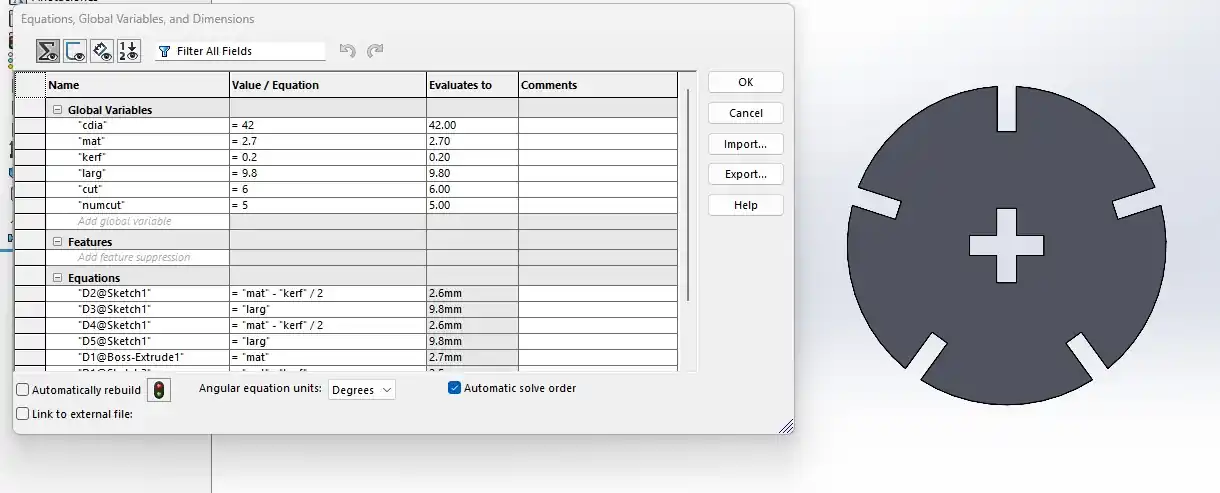
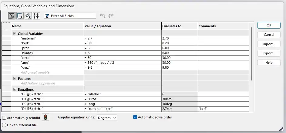
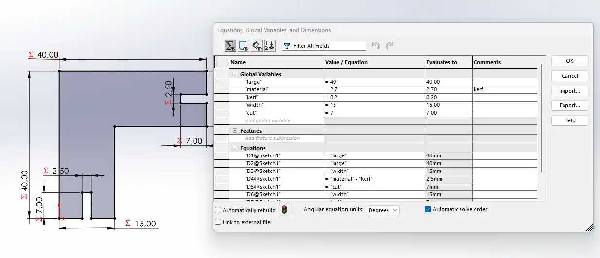
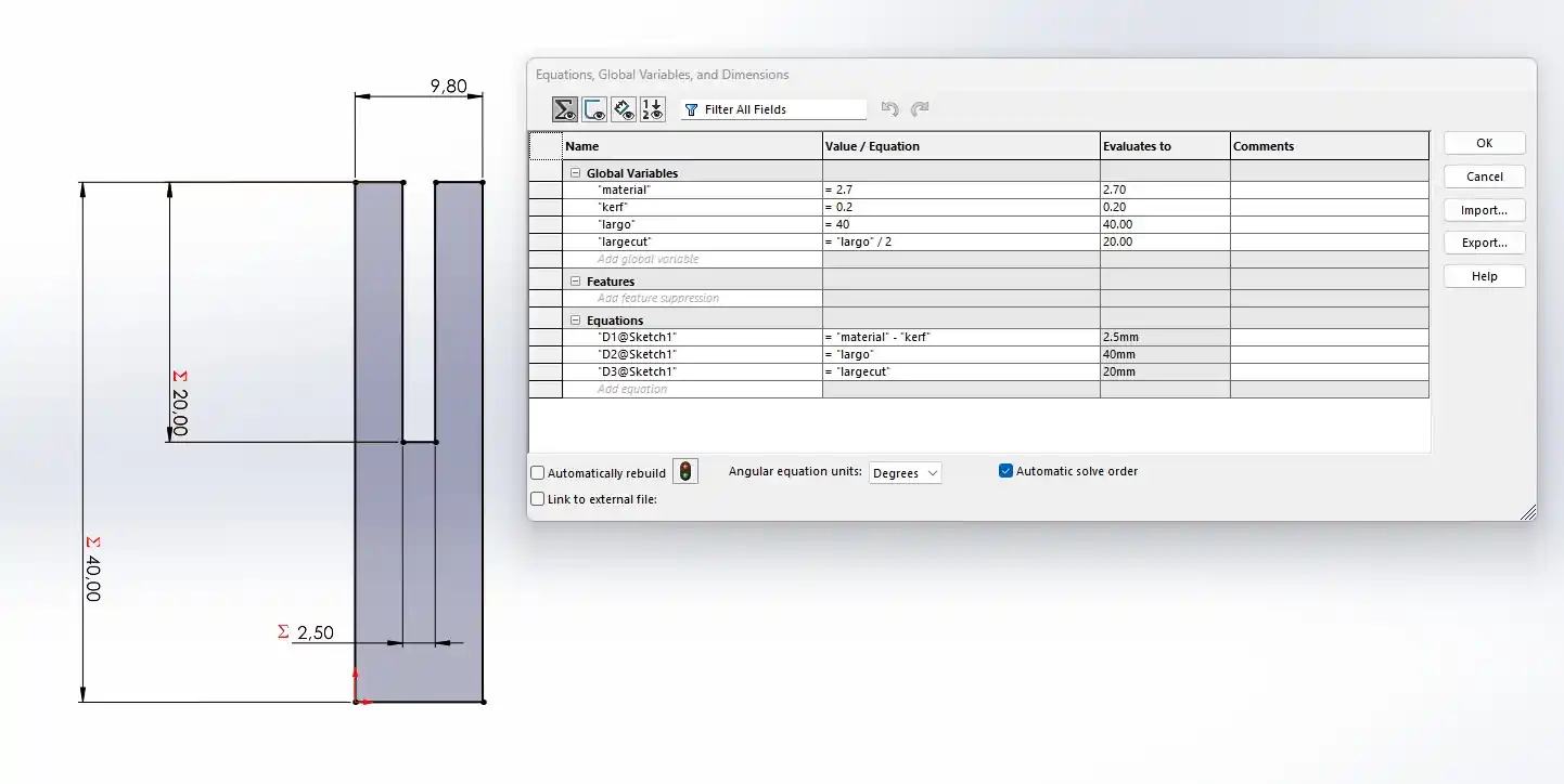
- The Equations, Global Variables, and Dimensions manager will open; here, you must declare your Global Variables by first giving them a name and then assigning a value.
- When using the Smart Dimension tool, you can call these global variables or perform operations by typing ="variable_name" in the dimension box. To use operations, follow this format: ="variable_name1" + "variable_name2".
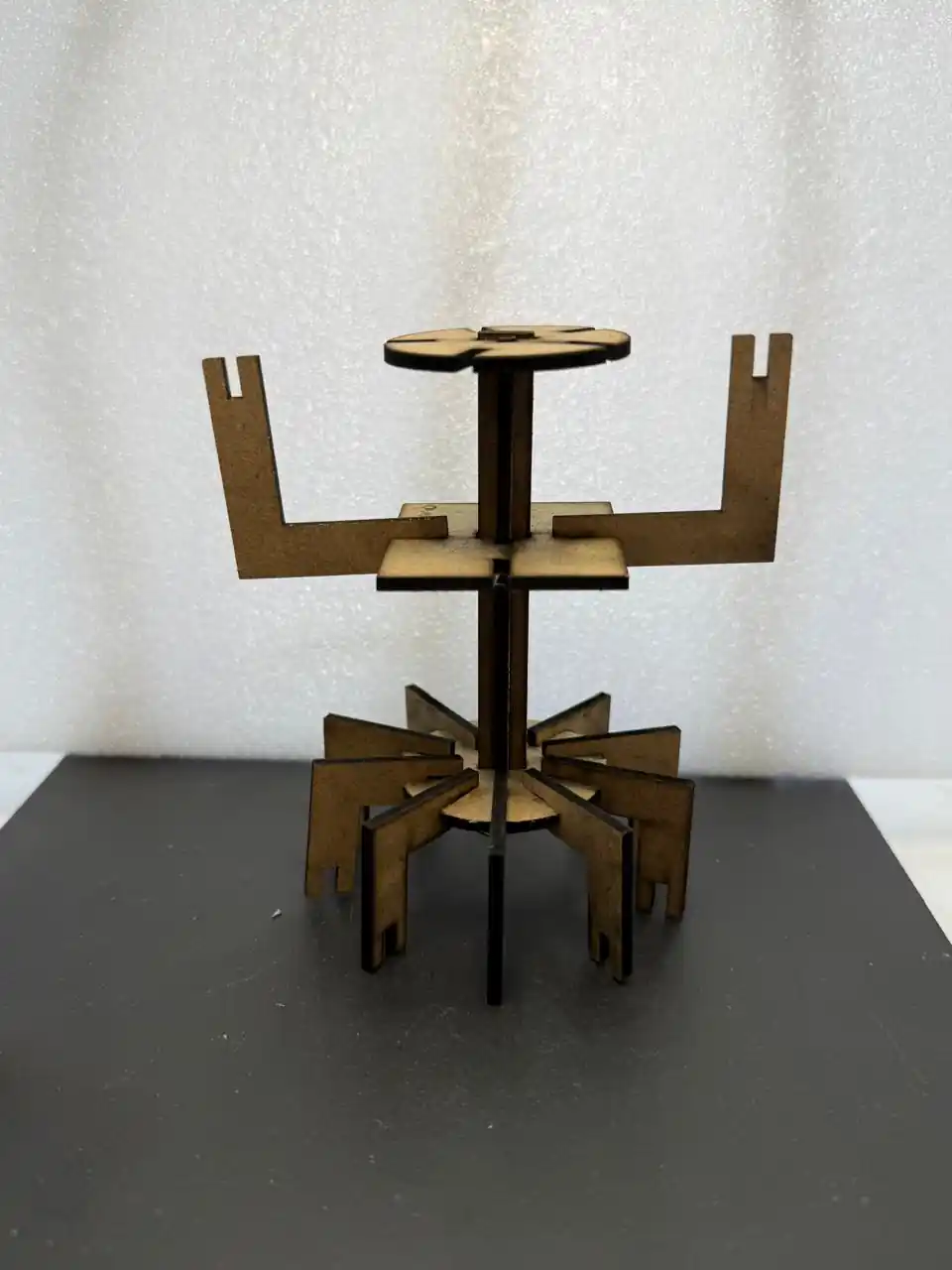
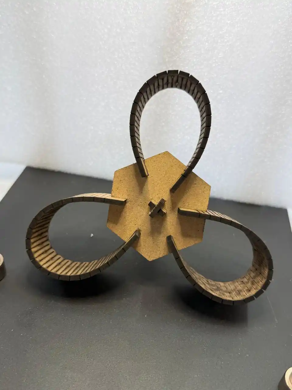
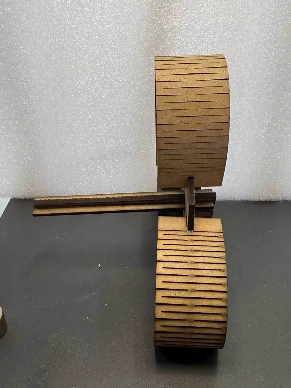
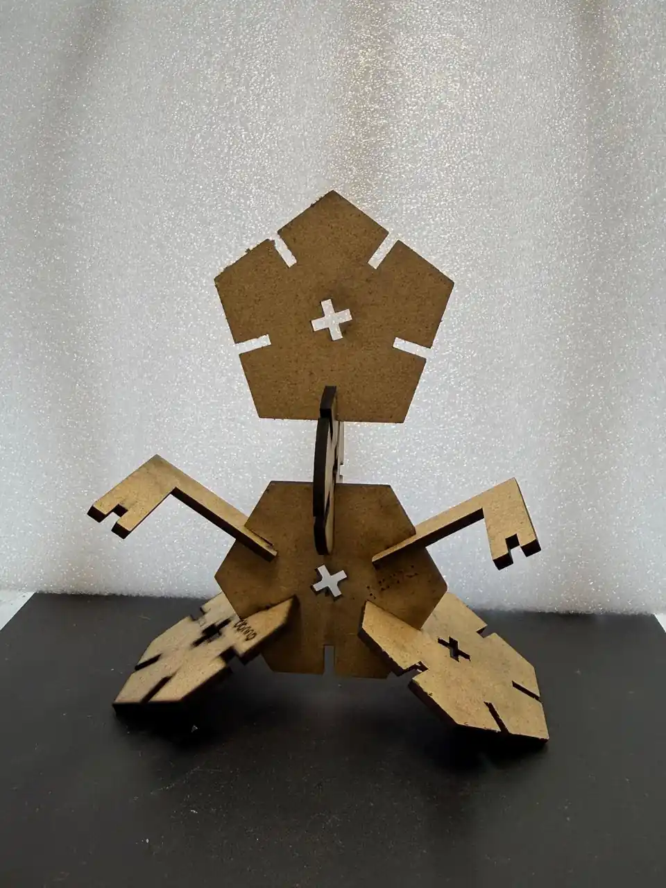
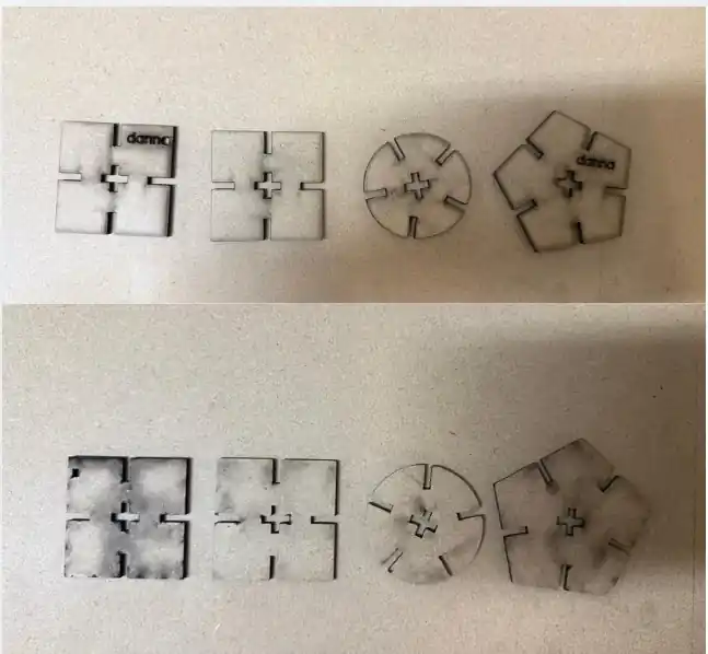
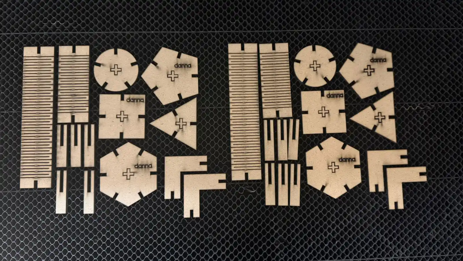
Parts of my kit
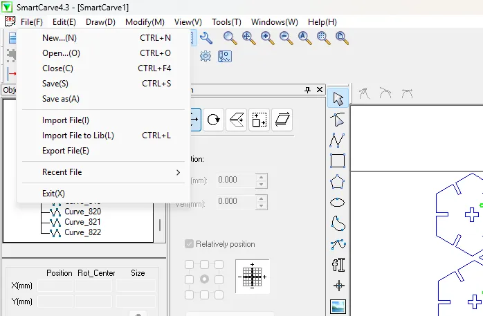
Export
To export the necessary files for the laser cutter software, follow these steps:
- Save the parts previously created.
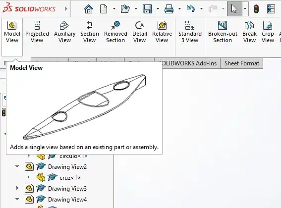
- Open SolidWorks and create a new Drawing.
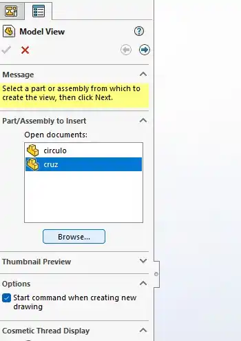
- Select the Model View tool.
- Add the desired part using the Browse option in the menu.
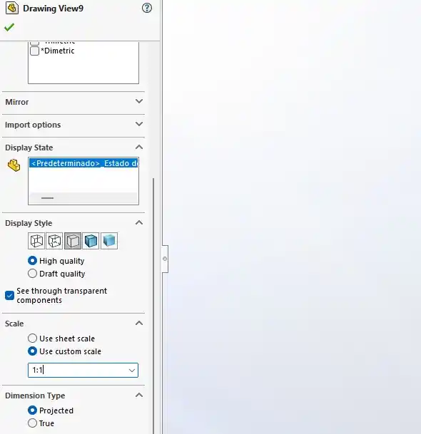
- Drag and drop the part onto the drawing sheet.
- Double-click on the part to change the scale of the drawing as needed.
- Go to Save As and select the DXF format.
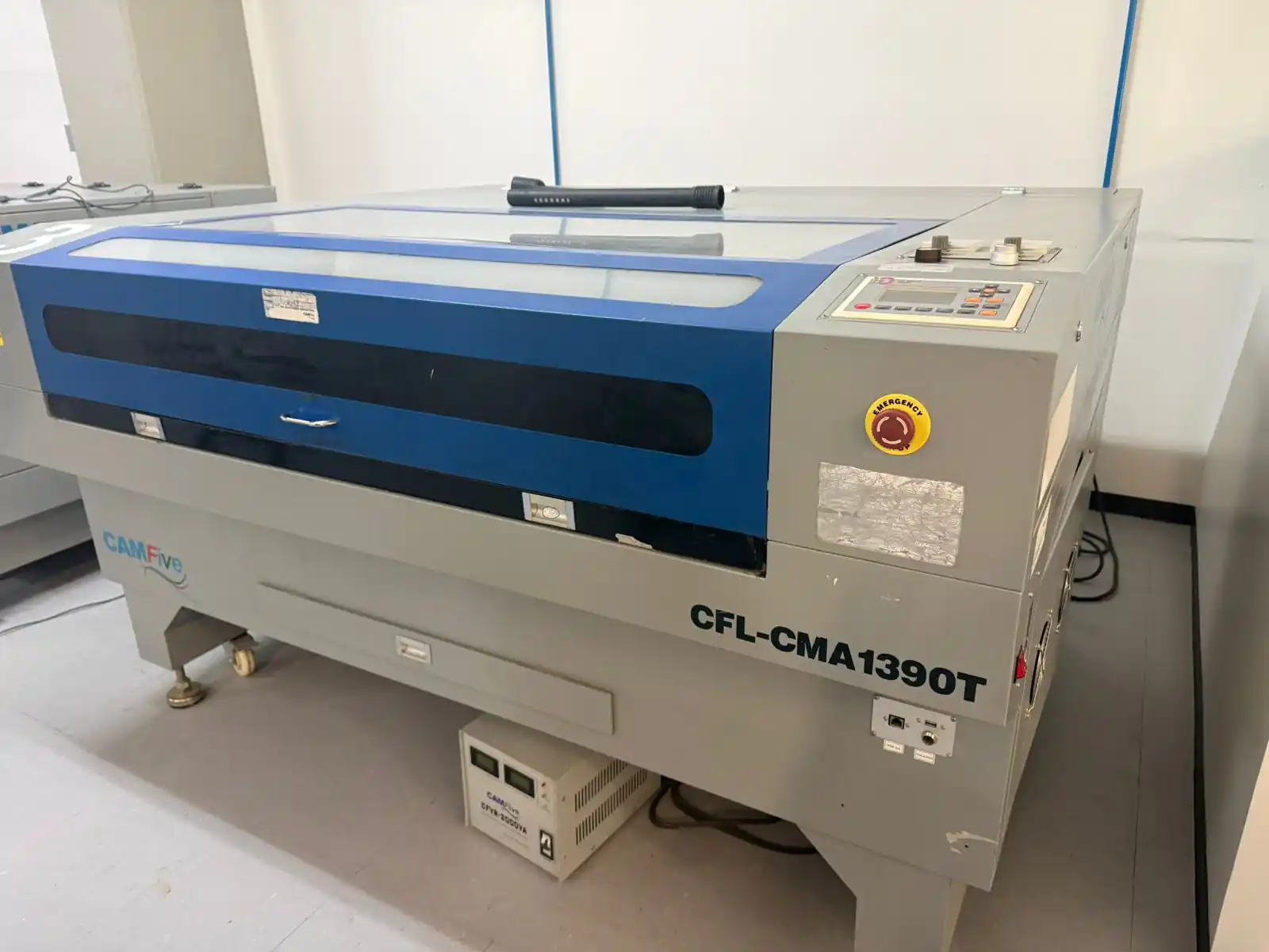
2. Laser Cutter
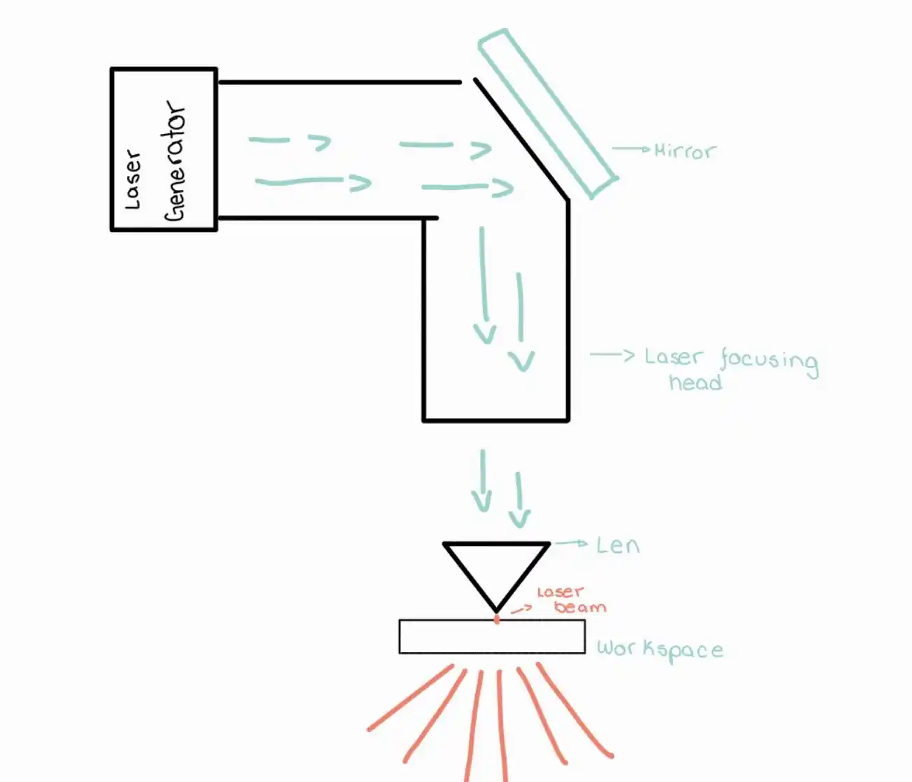
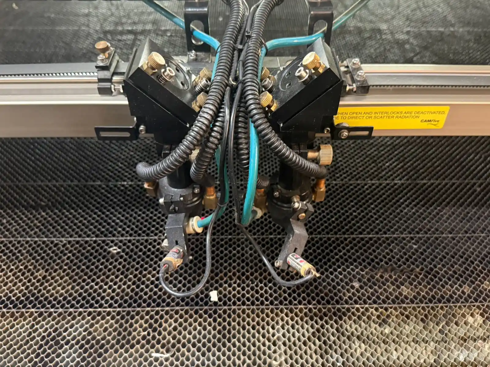
Laser Cutting Head Components
- Laser Generator:This is the light source that creates the beam. It is usually a CO2 tube that generates a high-power infrared beam.
- Beam Bender (Mirror):Its function is to redirect the laser path (which exits the generator horizontally) downward toward the material.
- Focusing Lens:One of the most critical parts. It concentrates the wide light beam into an extremely small and powerful point (called a "spot") on the material's surface.
- Laser Focusing Head:The structure that protects the lens and mirrors, moving along the X and Y axes to execute the design.
- Nozzle:The tip where the laser exits. In addition to directing the beam, pressurized air (air assist) usually passes through here to blow away burnt material, prevent fires, and protect the lens from debris.
- Focal Length:The exact distance between the lens and the point where the laser is thinnest and most powerful. For this week's task, correctly adjusting the focus is vital for achieving a clean cut.
- Workpiece:The material you are going to cut or engrave, such as wood, acrylic, or cardboard.
For the calibration is important to maintain a distance of 5mm between the nozzle and the material.
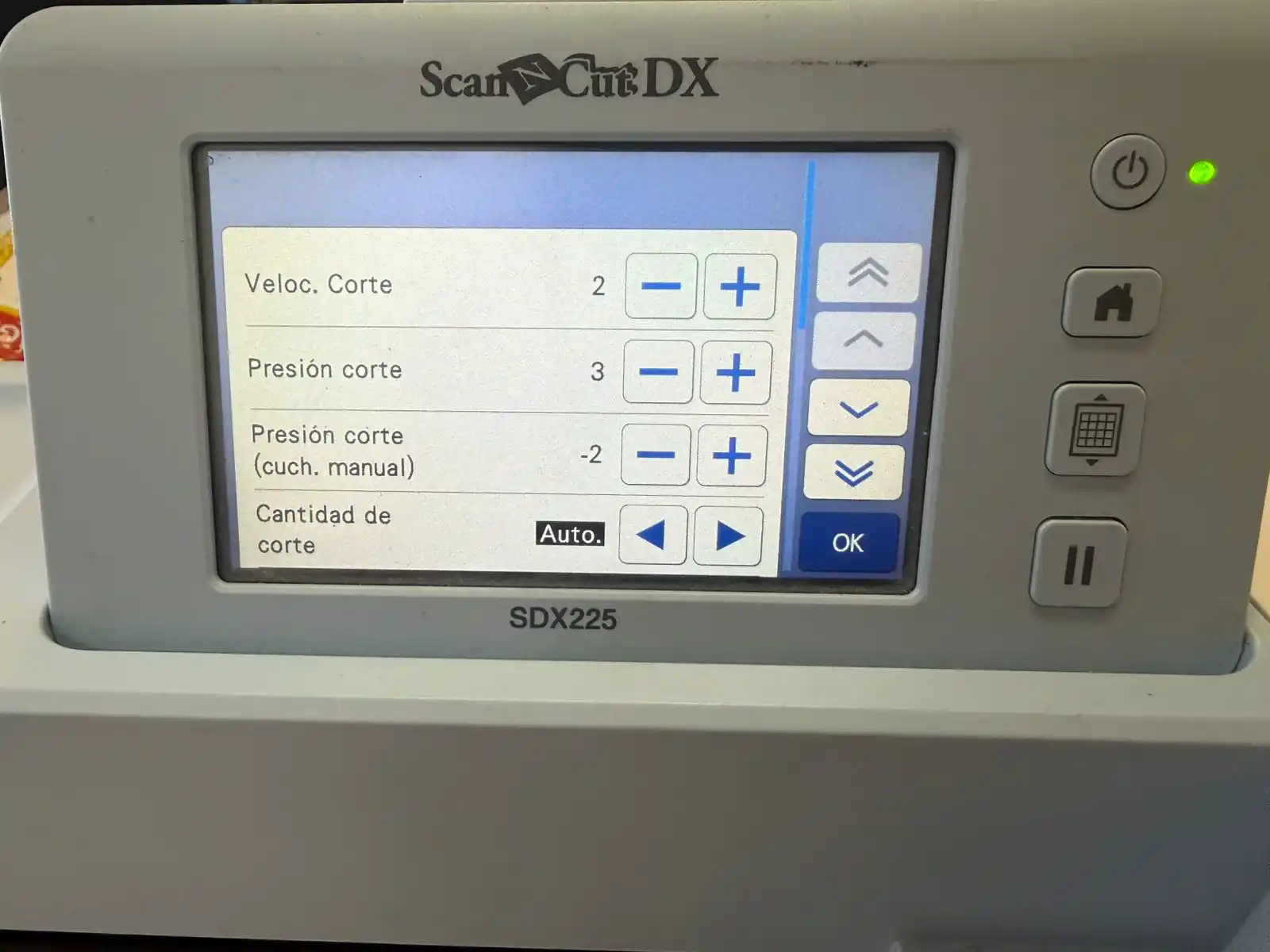
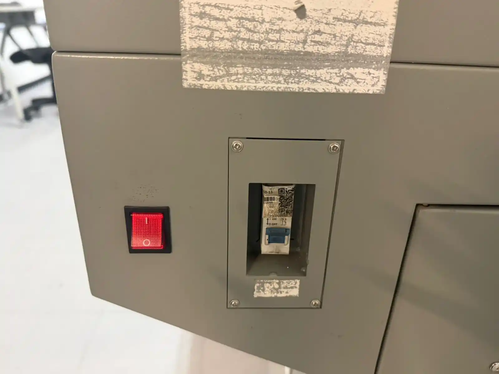
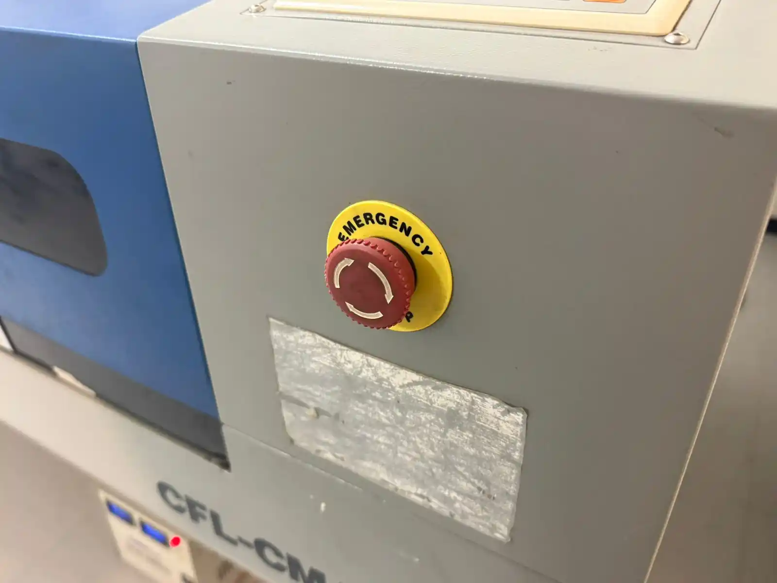
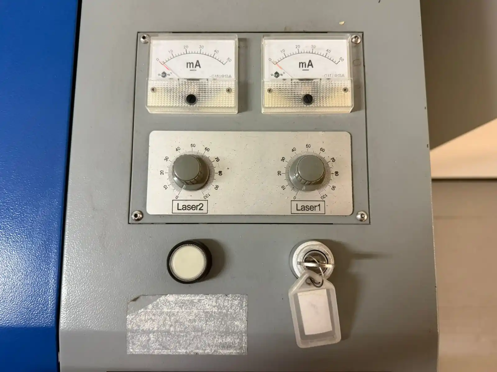
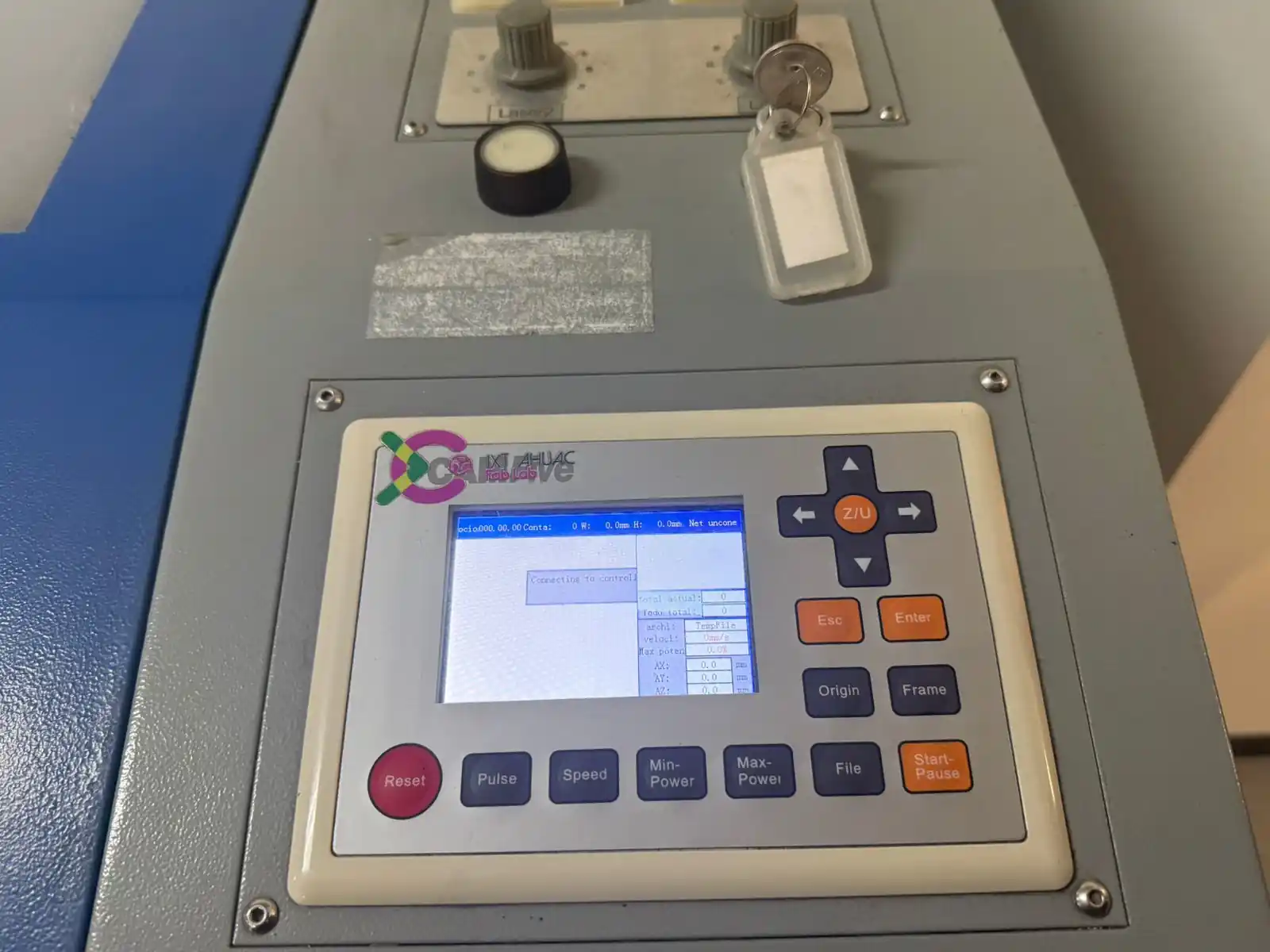
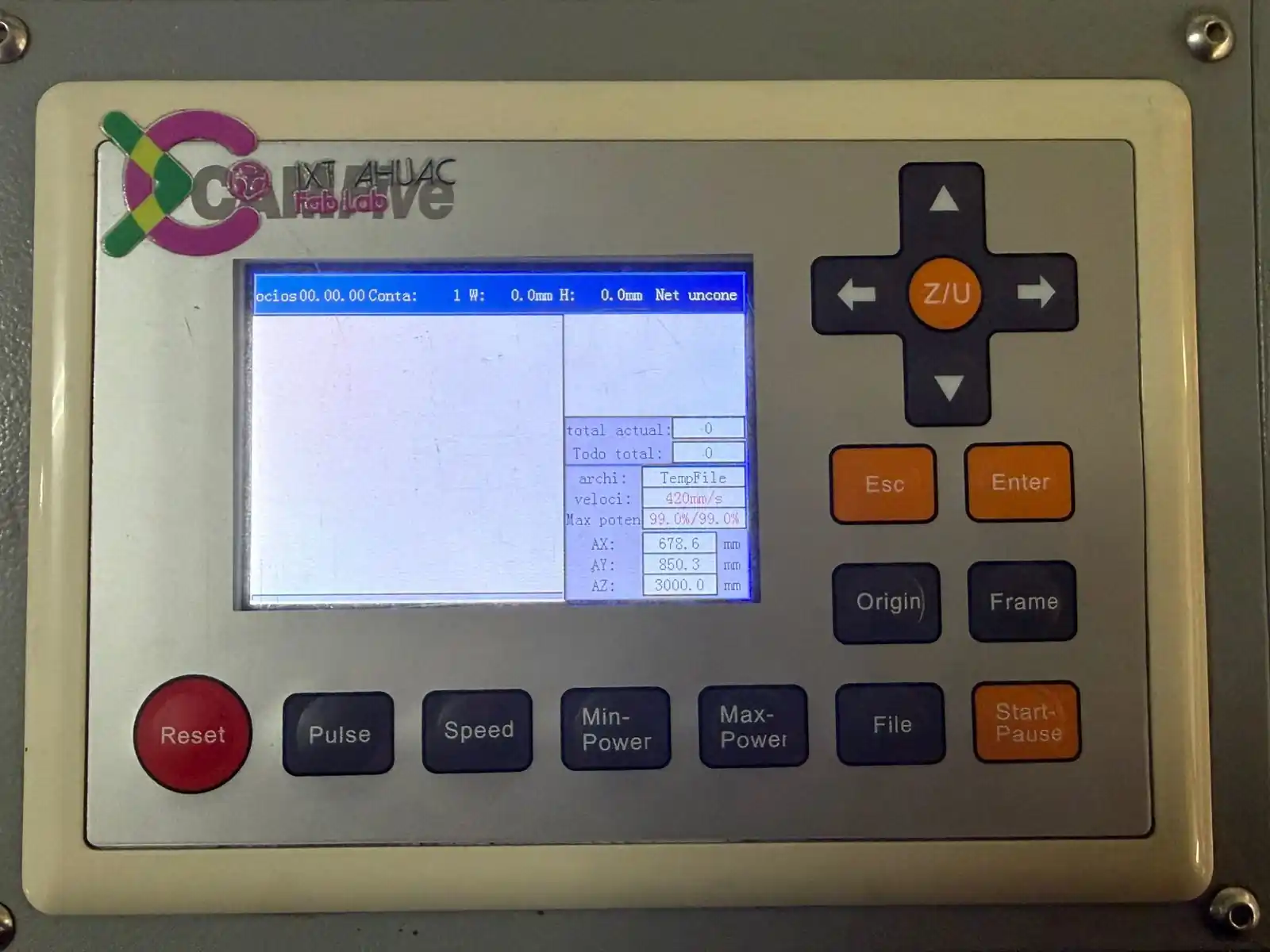
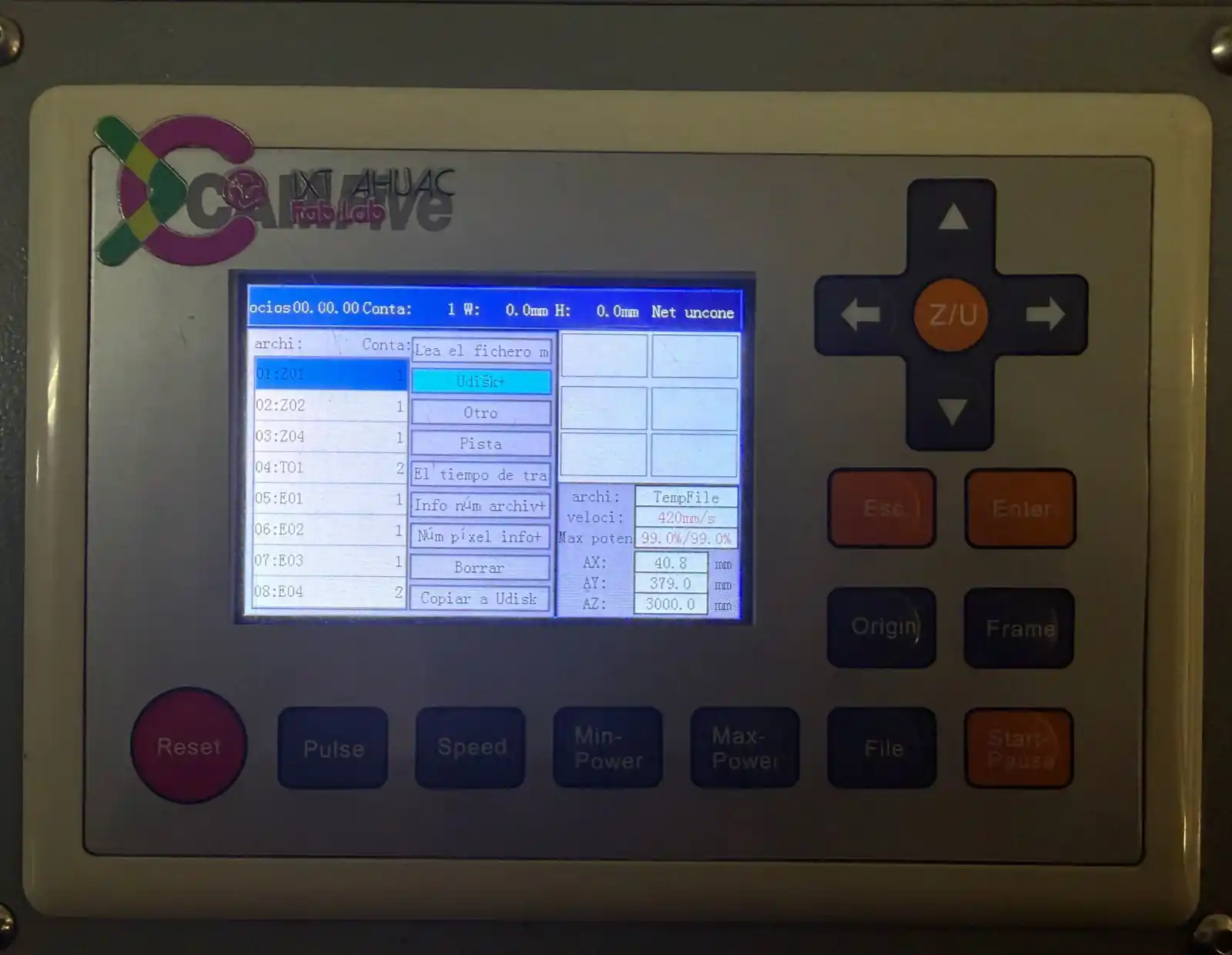
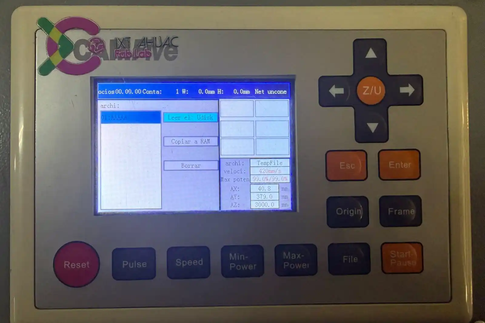
Machine Controls
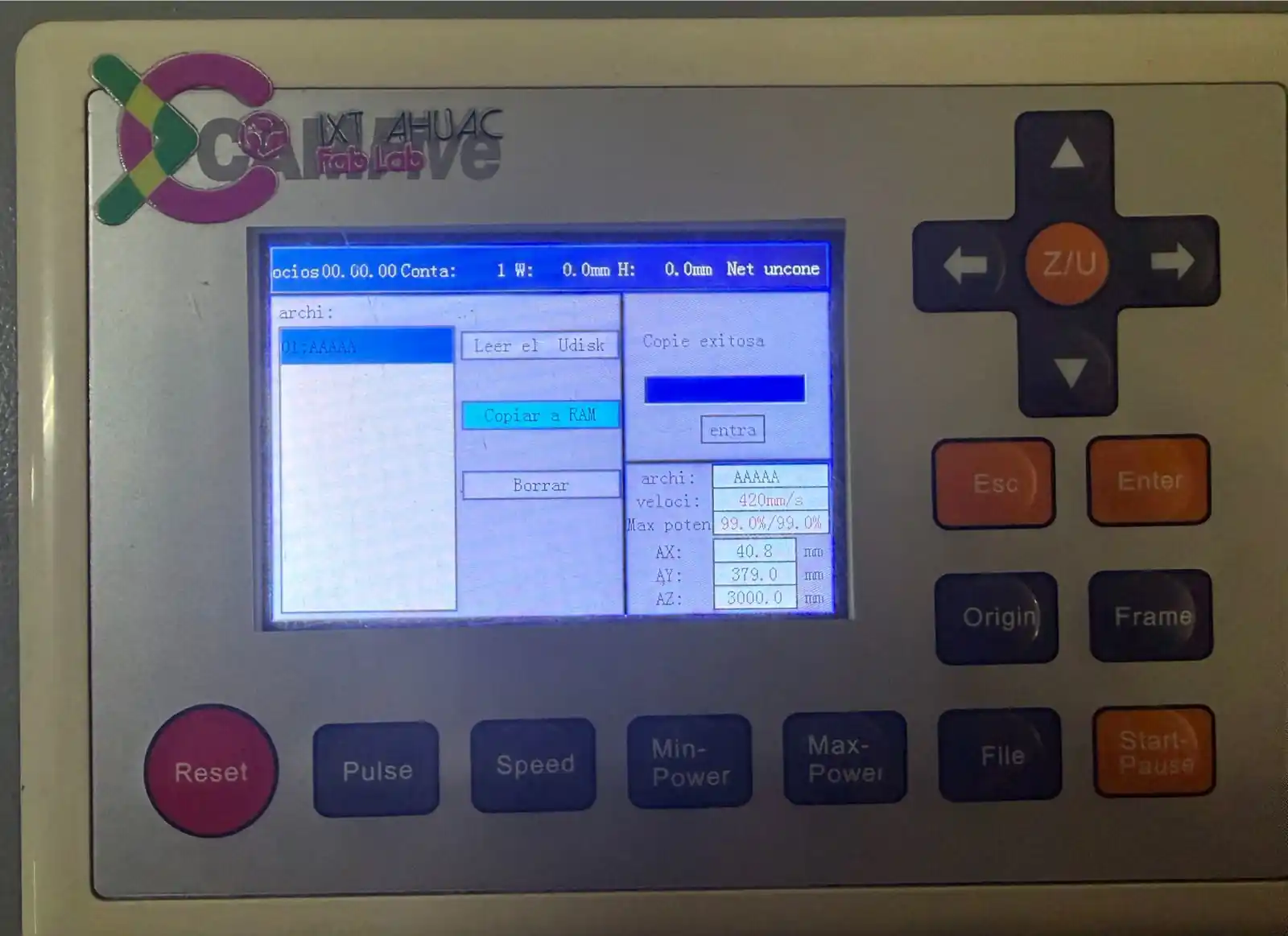
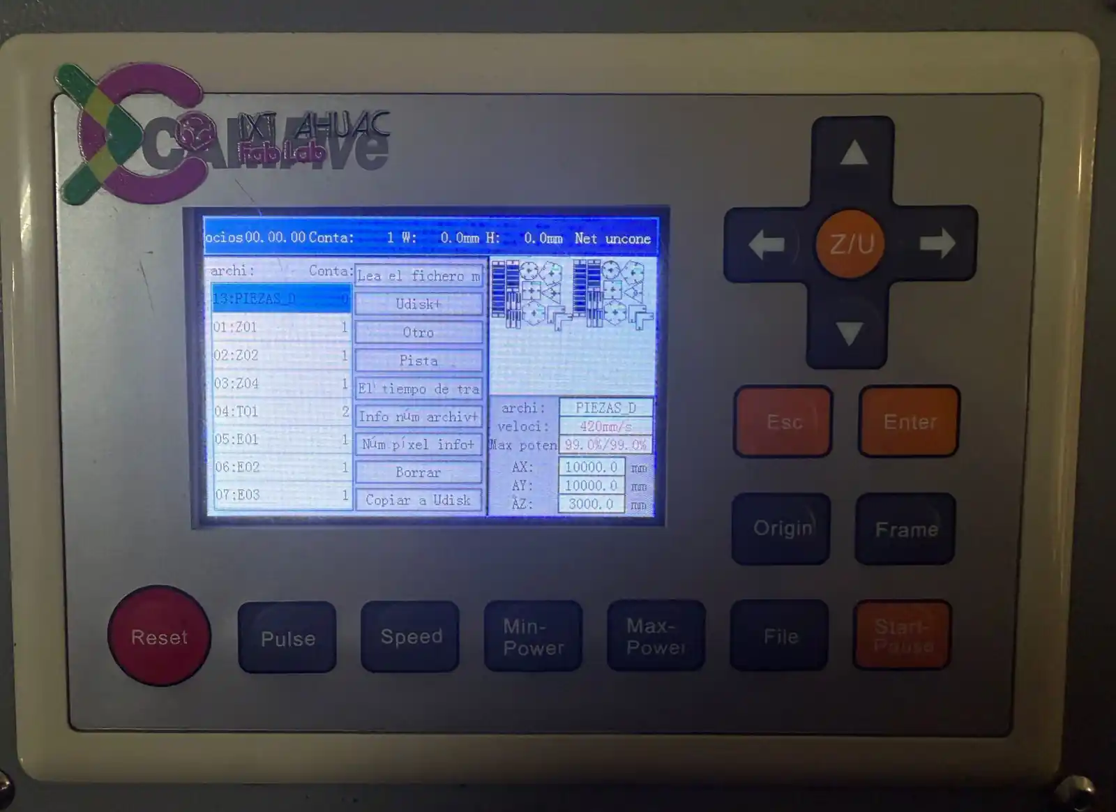
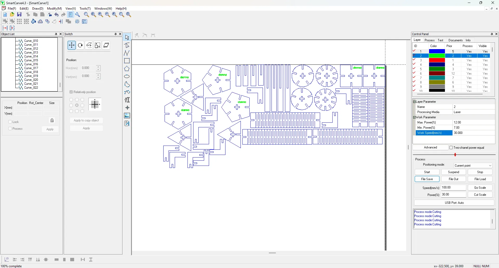
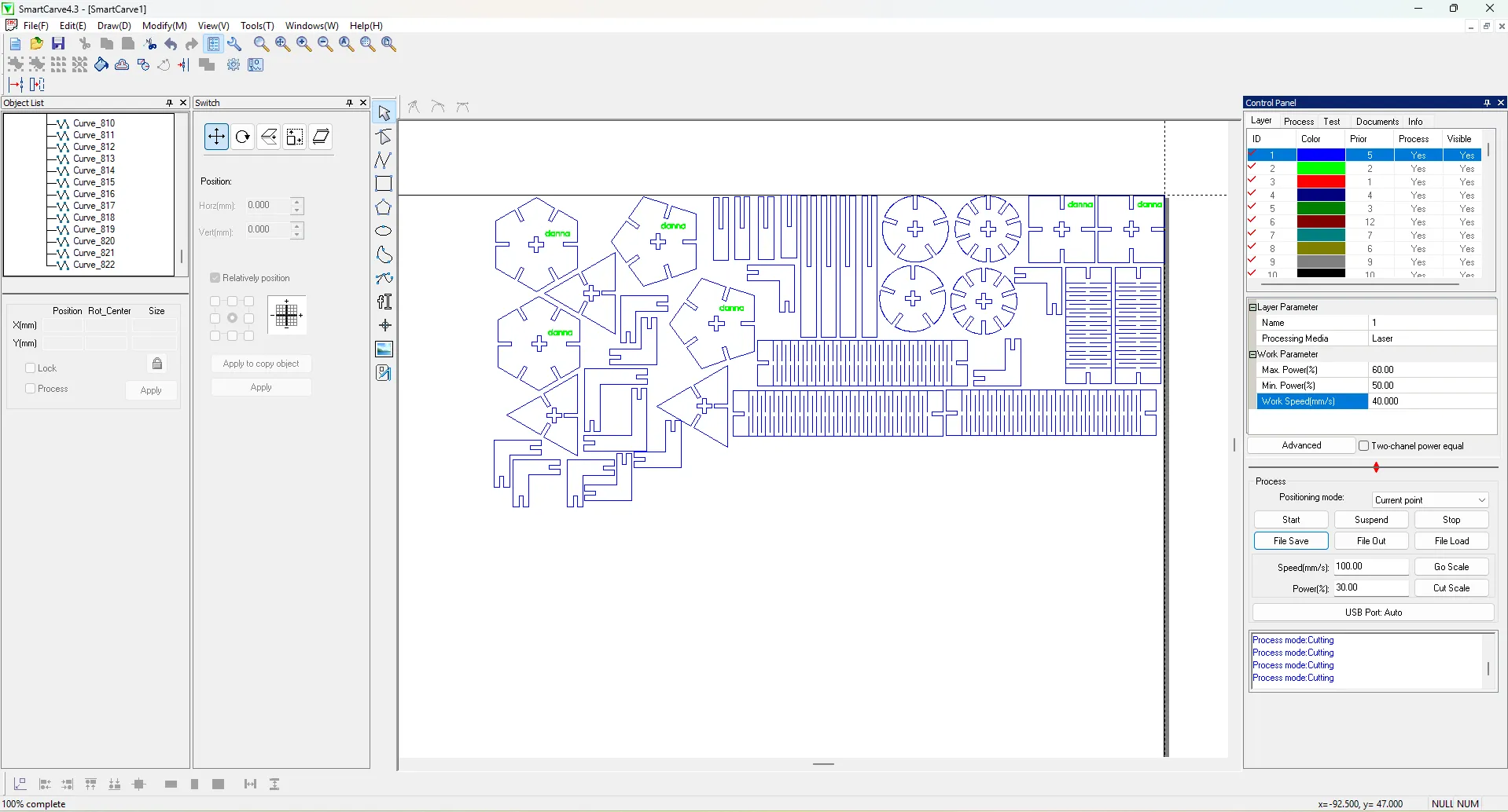
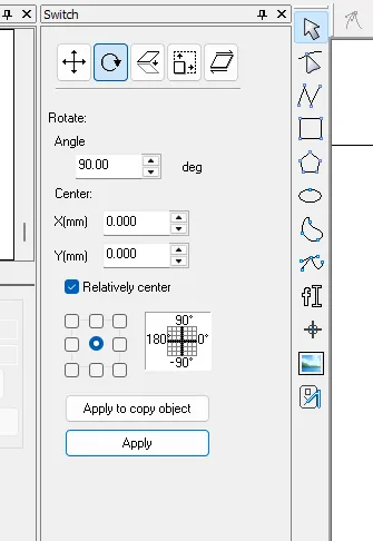
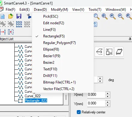
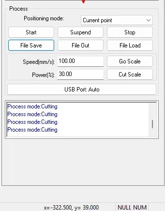
3. Smart Carve
To operate the laser cutter, you must use the SmartCarve software. Please note that this program will only open if the specialized USB security dongle (key) is inserted; otherwise, the software will not function.
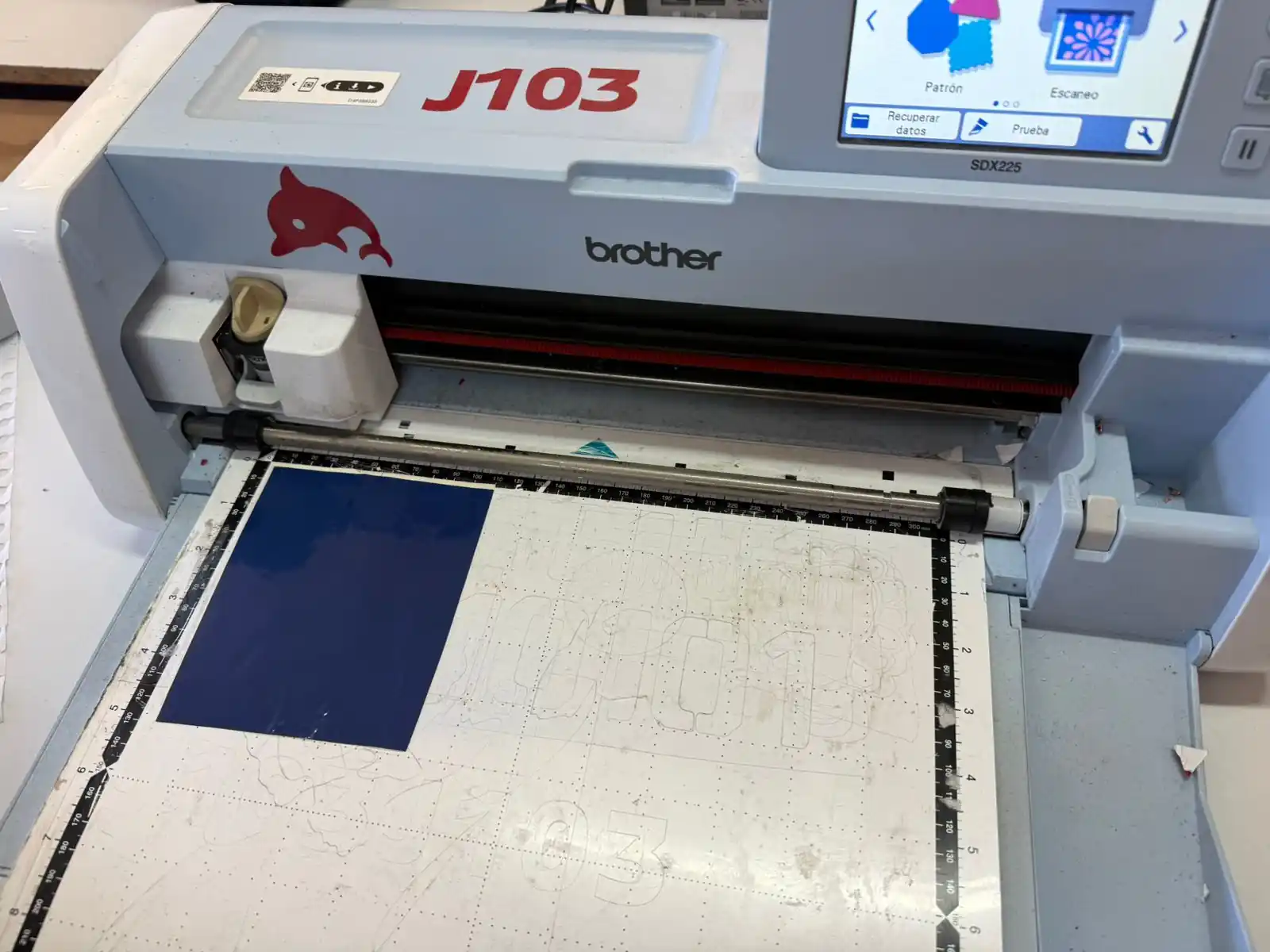
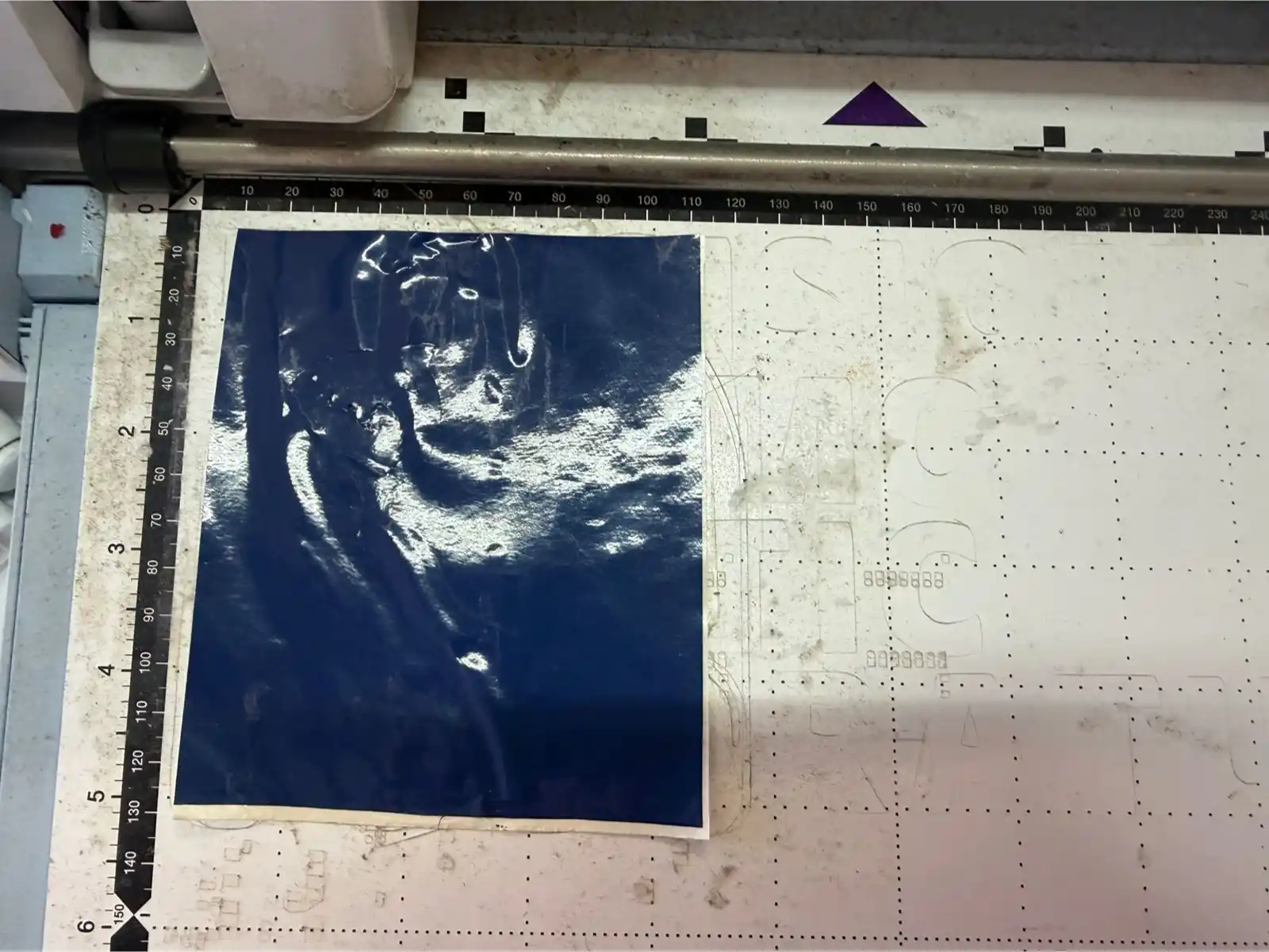
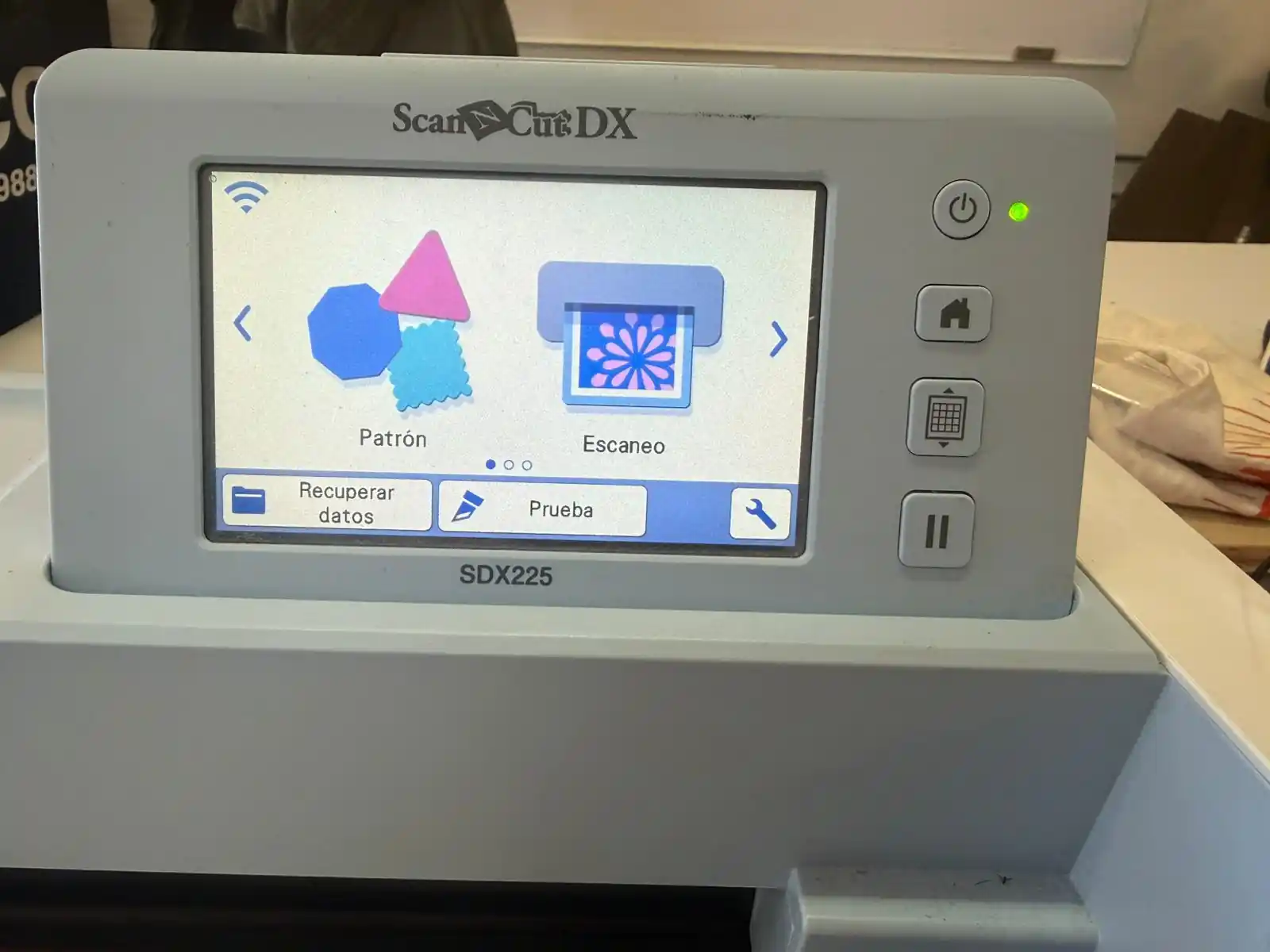
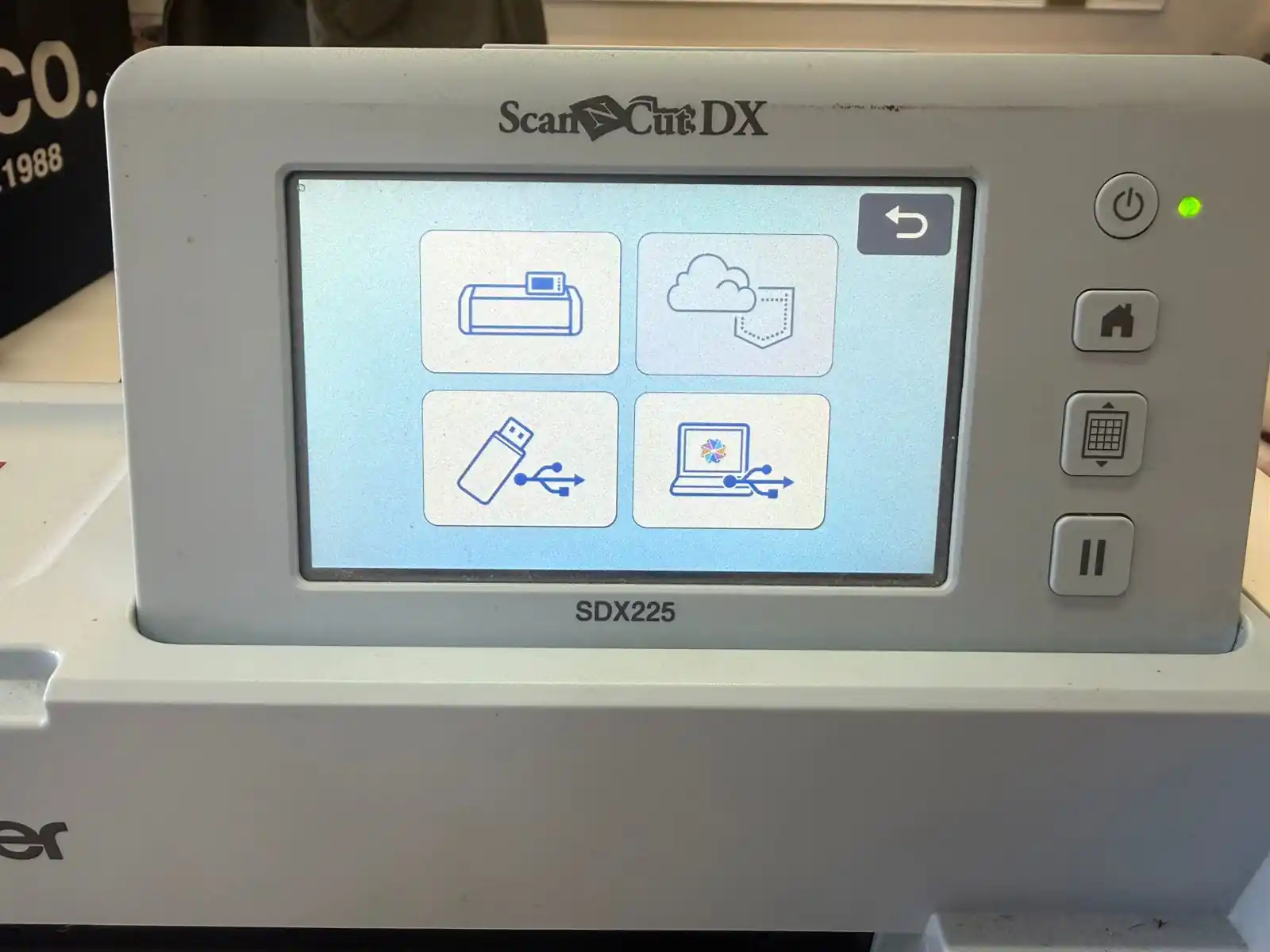
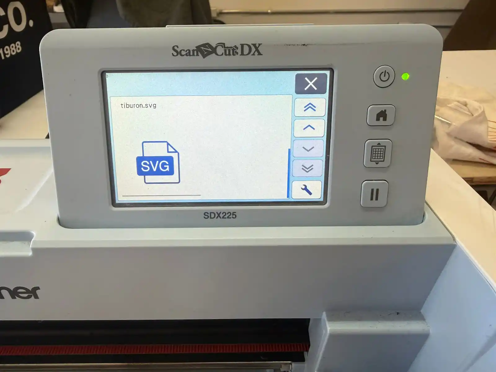
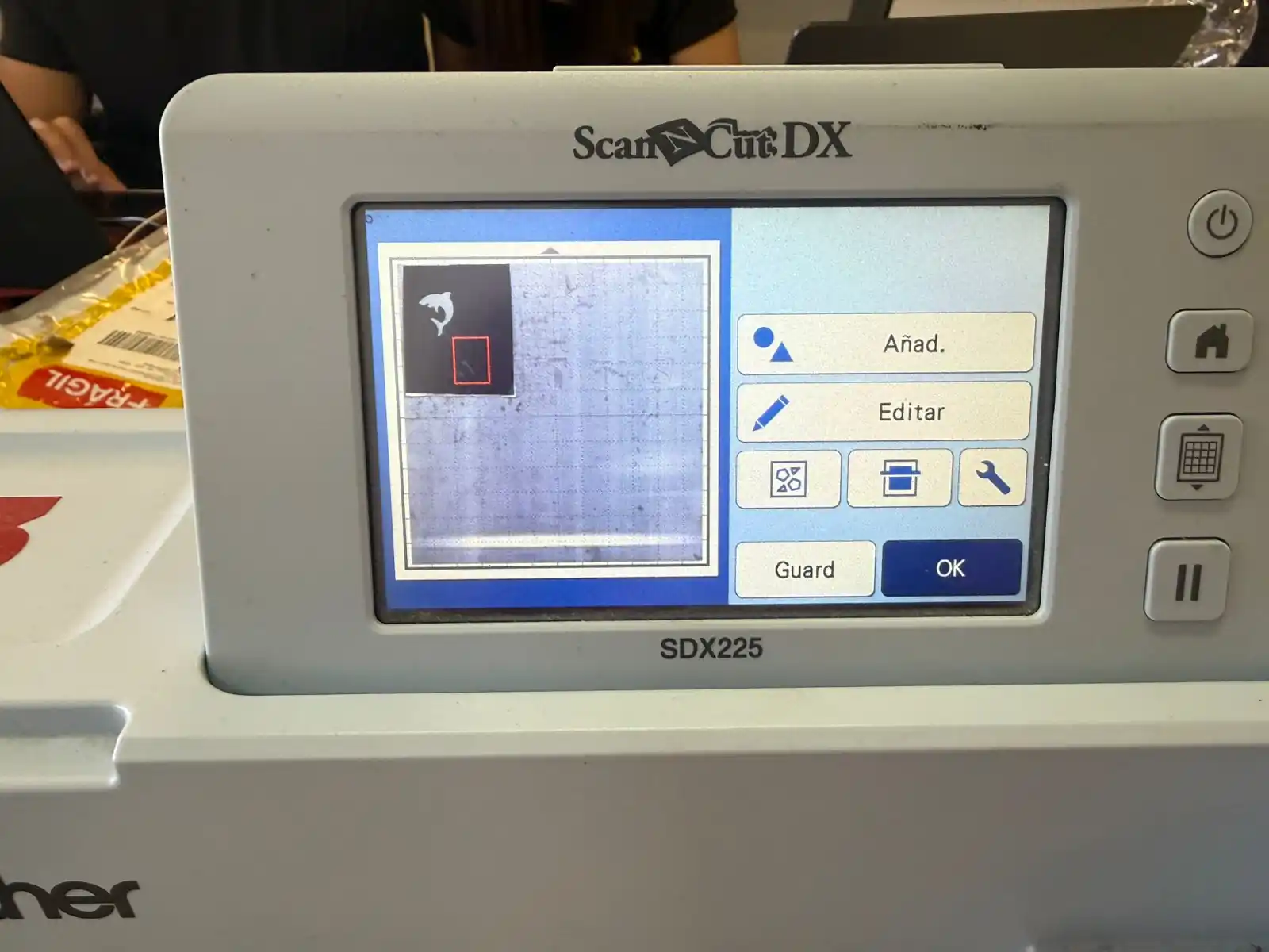
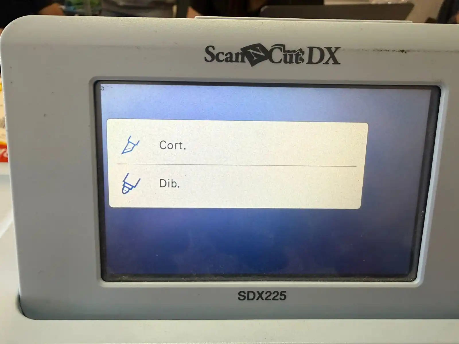
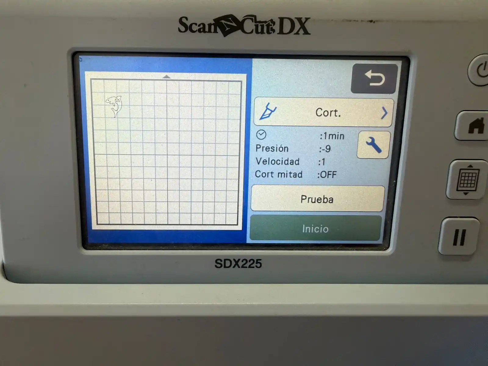
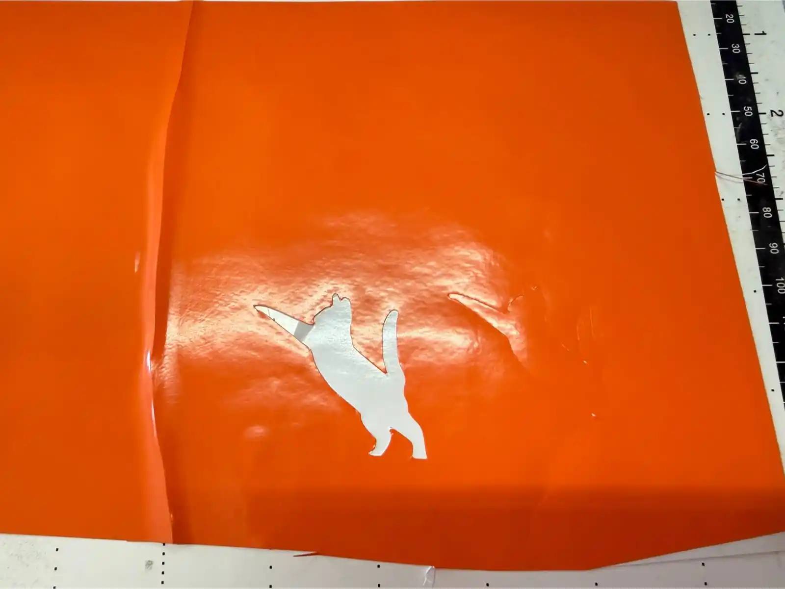
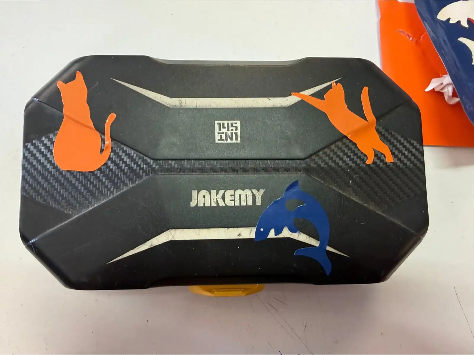
4. Vinyl Cutter
I selected images of a cat and a shark for this task. To prepare them, I processed the files in Inkscape to create vector paths, which is a necessary step for the vinyl cutter to follow the outlines accurately. You can see how I vectorized mi images in the Week 2 assignment.