In this assignment, I designed a possible final project using computer-aided design tools. I worked with 2D and 3D models to visualize the concept and understand its structure and functionality.
For the 3D software, I made the hamster base for my final project to house the motors and electronics, while for the 2D software, I created the logo of my project.
3D Modeling Software
Three-dimensional design allows for the construction of a complete digital prototype to evaluate how parts fit together before physical fabrication.
Two-dimensional design focuses on technical drawing and flat composition. It is essential for manufacturing processes that use sheet or laminated materials.
It is a 3D Computer-Aided Design (CAD) software widely used in engineering and industrial design, which allows for the creation of precise models of parts and assemblies, the simulation of their performance, and the generation of technical drawings.
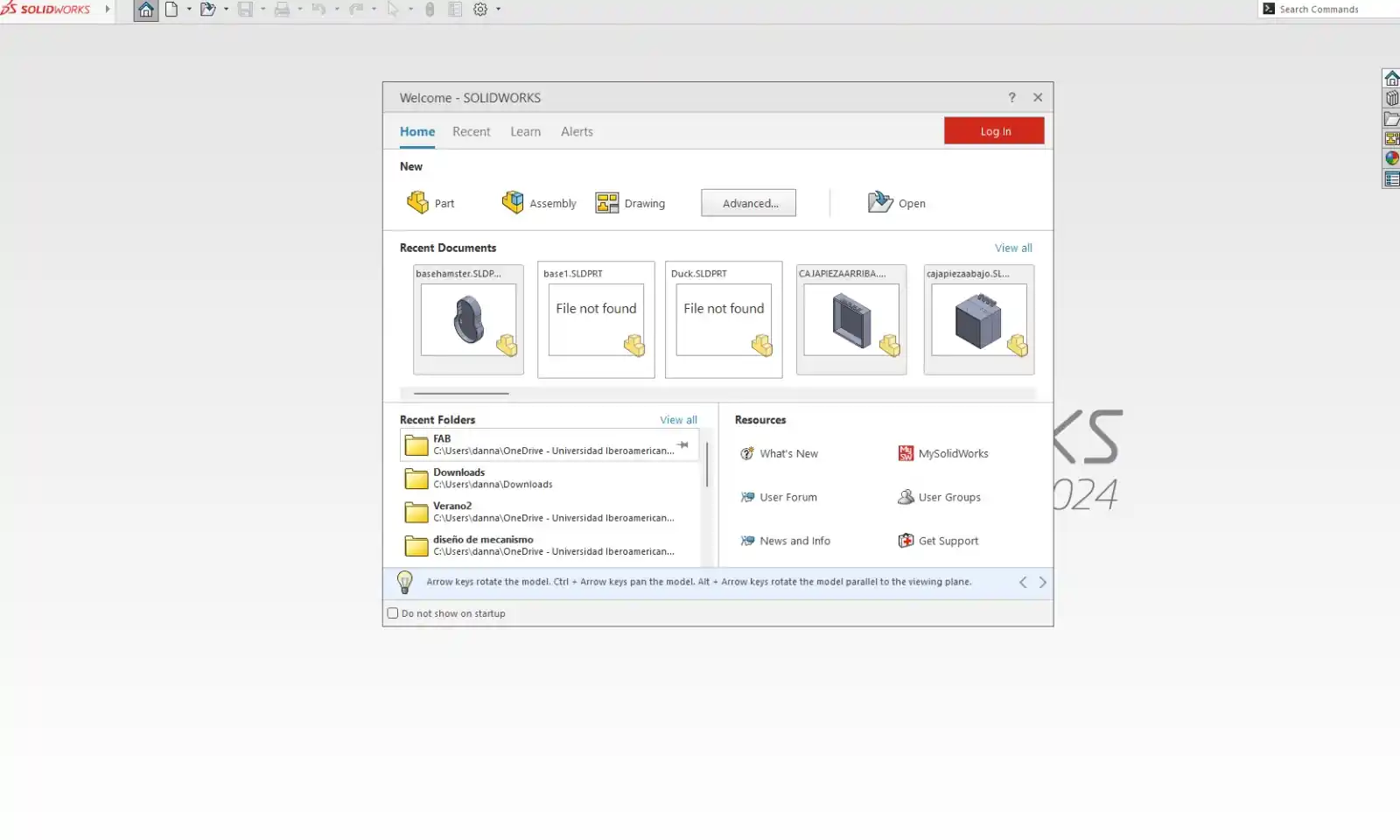
HOME PAGE
On the SolidWorks home page, there are three different options:
Part: where you can create new components.
Assembly: where you can create assemblies using existing parts.
Drawing: which is used for creating drawings.
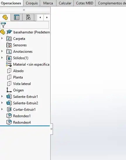
Feature List
The Feature List is your design history, located on the left side of the page. It records every step you take, such as sketches and extrusions, so you can easily go back and edit them at any time.
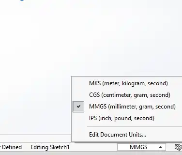
Workspace units
To change the units in your document, click in the bottom right corner and select the unit system you want.
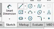
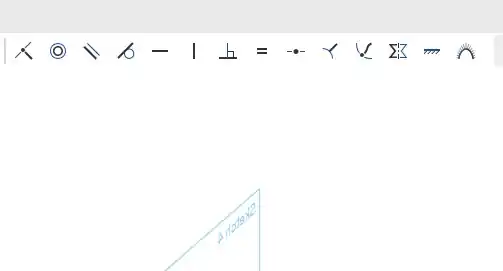
sketch tools
To create a sketch of our part, you must select the 'Sketch' option from the main menu and then choose the plane where you wish to begin your design.
Afterward, these are some of the tools we can use:
Smart Dimension: The primary tool for defining the size and location of entities. By selecting it and clicking on a line or circle, you can set exact measurements such as length, radius, or angle.
Line: Used to draw straight line segments.
Circle: Creates circles, typically starting from a center point and moving outward to define the radius.
Spline: Creates smooth, organic curves based on control points.
Rectangle: Allows you to draw quadrilaterals quickly. By default, it uses the "two-point" method (opposite corners).
Centerpoint Arc: Used to draw arcs by first defining the center, then the start point, and finally the angle of the arc.
Ellipse: Creates elliptical shapes by defining a major and a minor axis.
Text: Allows you to insert letters or numbers into the sketch, which can later be extruded to create engravings or reliefs on the part.
Polygon: Draws shapes with multiple equal sides, such as hexagons or pentagons.
Sketch Fillet: Converts the sharp corners between two lines into smooth arcs with a specific radius.
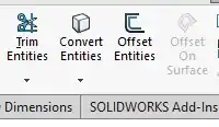
sketch tools
Trim Entities: Used to cut or remove unwanted segments of lines or curves.
Offset Entities: Creates a parallel copy of a selected line or shape at a specified distance.
Convert Entities: Projects the edges of existing 3D geometry onto the current sketch plane, allowing you to reference those edges in your sketch.
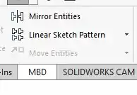
sketch tools
Mirror Entities: Creates a symmetrical copy of selected sketch entities across a centerline or axis.
Linear Sketch Pattern: Used to replicate selected geometry in a straight line with defined spacing and a specific number of instances.
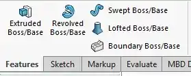
Features
Extruded Boss/Base: Adds depth to a sketch along a linear path to create a 3D solid.
Revolved Boss/Base: Rotates a sketch profile around a centerline to create cylindrical or spherical geometry.
Swept Boss/Base: Moves a 2D profile along a specific path to create complex, guided shapes.
Lofted Boss/Base: Creates a 3D shape by blending multiple sketch profiles together.
Boundary Boss/Base: A high-precision tool used to create complex surfaces or solids by defining constraints in multiple directions.
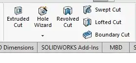
Features
Transfo the 2D lines into a 3D object using Boss-Extrude.
Extruded Cut: Removes material by pushing a sketch profile through a solid body in a linear direction.
Hole Wizard: A specialized tool used to generate standard threaded or clearance holes.
Revolved Cut: Removes material by rotating a sketch profile around a centerline.
Swept Cut: Removes material by following a specific path with a 2D profile; ideal for complex grooves or internal channels.
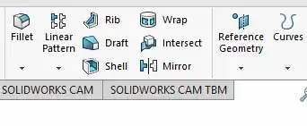
Features
Fillet: Rounds the edges of a solid to improve aesthetics and reduce stress concentrations.
Reference Geometry: Used to create new planes, axes, or coordinate systems.
Mirror: Used to create a symmetrical copy of one or more features across a reference plane.
Linear Pattern: Allows you to replicate 3D features in one or two linear directions.
My job
I started working on Solid using these tools.
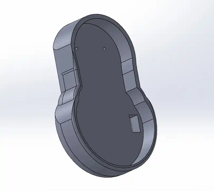
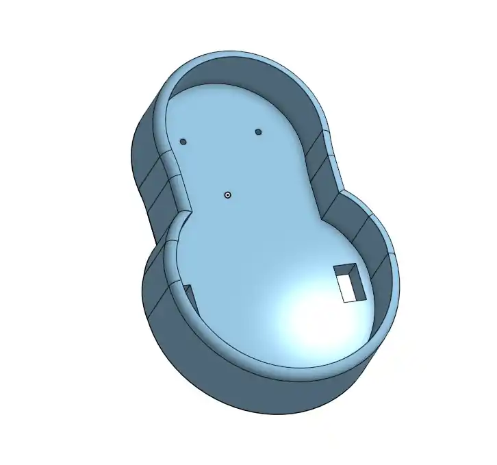
Base for my hamster
This week, I modeled a part that will serve as the base for my hamster for my final project; I will place the motors and the electronics on this base.
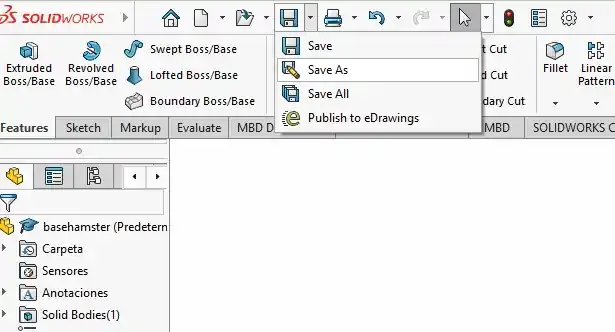
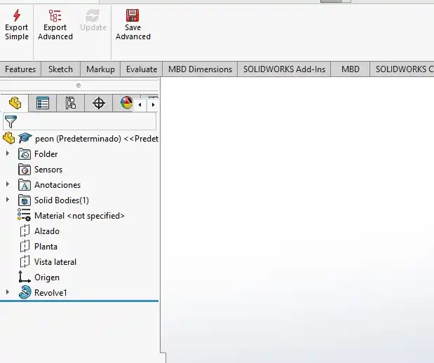
Export
To export our part from SolidWorks, go to the 'Save' option located at the top of the main view. Then, select 'Save As' and choose the destination, file name, and output format.
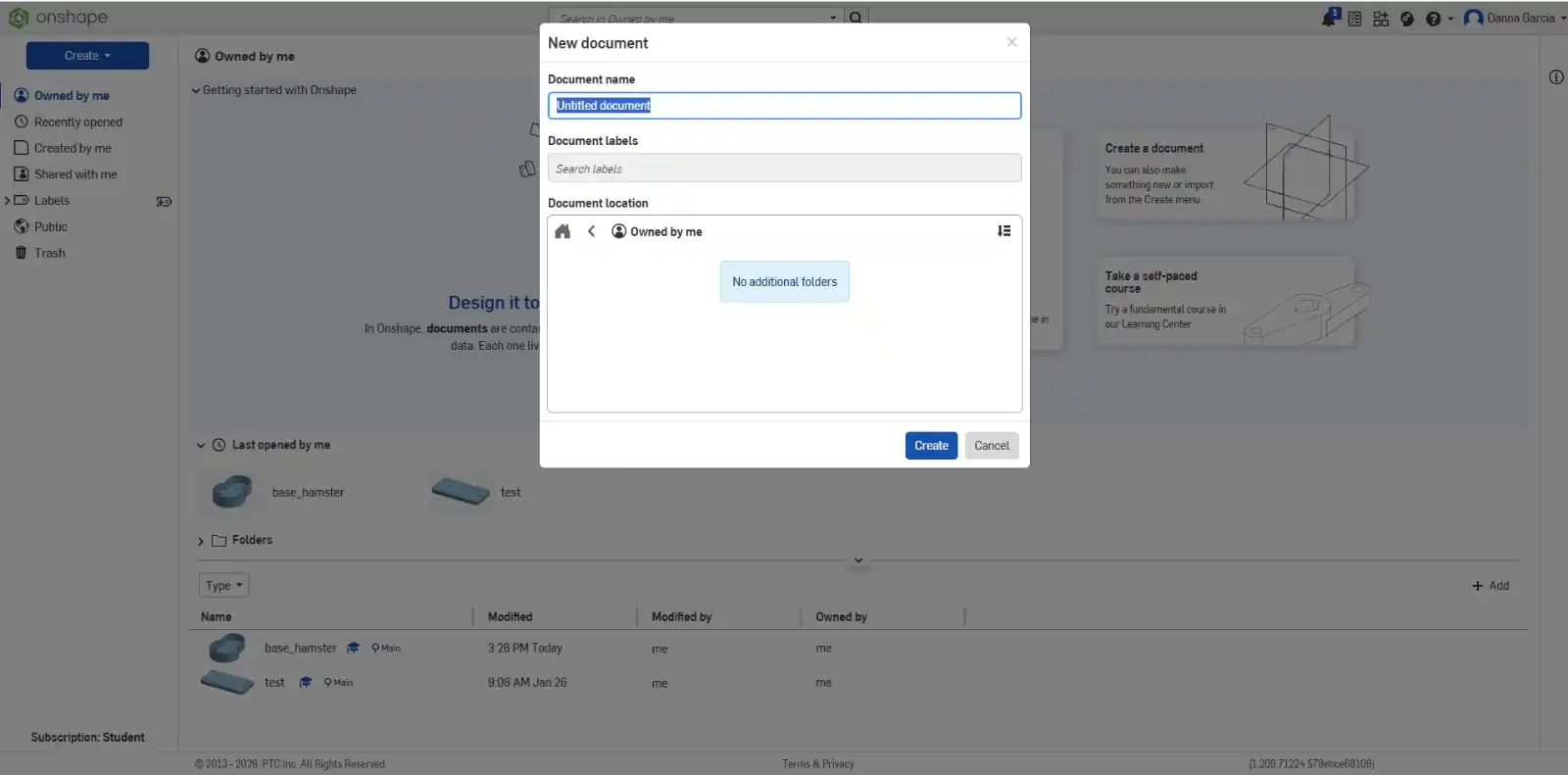
It is a professional parametric CAD system that works directly in the web browser. It allows for 3D modeling, assembly design, and the creation of technical drawings, with the advantage of allowing multiple people to work on the same design at the same time.
On the Onshape home page, you must click the 'Create' button and enter the name of your document
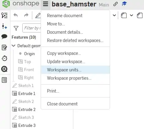
Workspace Units
To change the units of your document, click the three lines (menu icon) in the top-left corner and then select 'Workspace units' to make your changes.
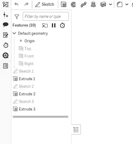
Features List
The Features List is the history of your design. It records every step you take, like sketches and extrusions, so you can go back and edit them easily at any time.
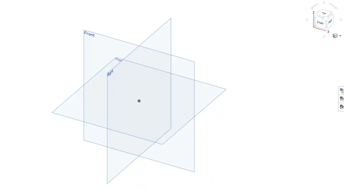
Axes
To begin designing, you must first choose a plane (Top, Front, or Right) to draw your sketch. You can use the Navigation Cube in the corner to change the view, and with the help of the center point, you can ensure your pieces are centered.
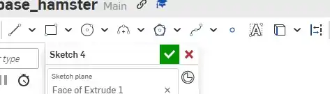
Sketch Tools
These tools are used to create the 2D sketches for our components.
Line:Used to draw the straight edges of the parts.
Rectangle:Used to create square or rectangular shapes quickly.
Circle:Used to draw holes, screw cavities, or round shafts.
Arc:Used to create curves or join points with rounded lines.
Polygon:Allows drawing figures with multiple equal sides.
Spline:Used to draw fluid, organic, or free-form curved lines.
Point:Used to mark specific coordinates or reference centers in the drawing.
Text:Used to write letters or numbers on the design surface.
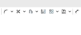
Sketch Tools
These tools are used to create the 2D sketches for our components.
Fillet: Used to round off sharp corners in a sketch.
Trim: Used to cut or remove unwanted parts of a line.
Offset: Creates a copy of a shape at a specific distance from the original.
Mirror: Reflects a shape across a line to create a symmetrical copy.
Pattern: Repeats a shape multiple times in a row or a circle.
Dimension: Used to set the exact measurements for the drawing.
Insert DXF/DWG: Used to import existing drawings from other software.
Constraints
These tools are used to constrain the behavior, position, rotation, or scale of one or more objects based on another.
Coincident: Used to join two points or a point and a line so they are always touching.
Concentric: Makes two circles or arcs share exactly the same center point.
Parallel: Ensures that two lines always maintain the same direction and never cross.
Tangent: Makes a line or circle touch another curve smoothly without crossing through it.
Horizontal: Forces a line to stay perfectly level.
Vertical: Forces a line to stay perfectly upright.
Perpendicular: Makes two lines cross each other at a 90° angle.
Equal: Used so that two lines or circles always stay the same size.
Midpoint: Joins a point exactly to the center of a line.
Symmetric: Makes two shapes identical relative to a center line.
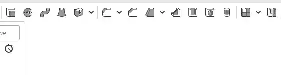
3D Modeling Tools
Extrude: Adds depth to a 2D sketch to create a solid part.
Revolve: Rotates a sketch around an axis to create rounded parts.
Sweep: Moves a sketch along a path to create things like tubes or wires.
Loft: Connects different shapes to create a smooth transition between them.
Thicken: Adds thickness to a surface.
Fillet: Rounds off the sharp edges of a 3D solid.
Chamfer: Bevels or angles the edges of a part.
Draft: Tilts the faces of a part.
Rib: Adds structural support to the part.
Shell: Hollows out a solid part, leaving only walls.
Hole: Automatically creates precise screw holes.
My job
I started working on Onshape using these tools.
Base for my hamster
This week, I modeled a part that will serve as the base for my hamster for my final project; I will place the motors and the electronics on this base.
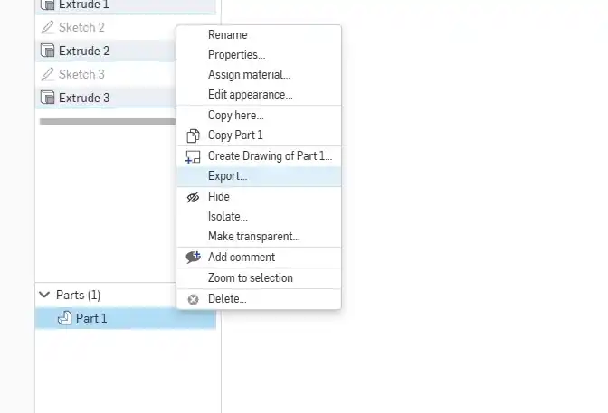
Export
To export your part, go to the Features List and right-click on the part to open the menu; then, select 'Export' to choose your preferred file format.
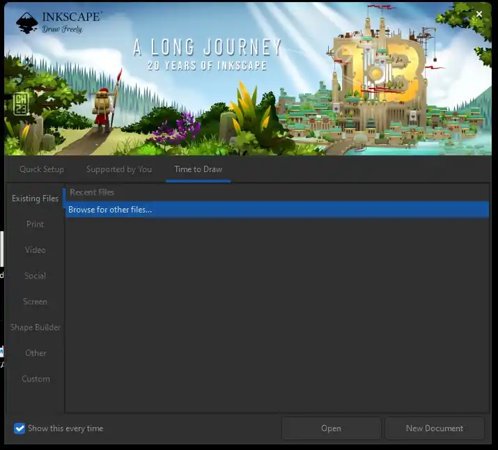
It is a free and open-source vector graphics editor for Windows, macOS, and Linux, used to create and edit illustrations, logos, diagrams, icons, and complex high-quality designs. These designs can be scaled without losing sharpness using the SVG format, making it ideal for web, print, laser cutting, and CNC.
When you open Inkscape, the first thing that appears is this window; here we can choose whether to open an existing document or a new document.
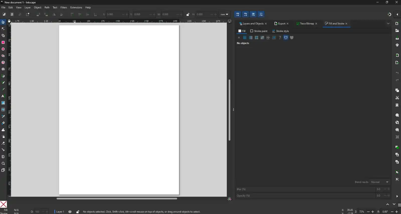
Now we are on the Inkscape main page. Here, we can find the main menus and the tools; on the right side, the settings for the tools we are currently using will be displayed.
To open an image that we have already downloaded, we must press the File menu, then select Open, and choose the image we want.
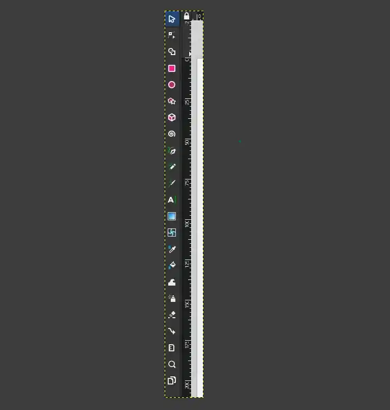
Toolbox
In our main window, on the left side, we find a toolbox where you select the necessary tools to create and edit your designs. Each icon represents a specific function:
Select and Transform Objects: To move, scale, or rotate objects.
Shape Creation: Drawing rectangles, circles, stars, and polygons.
Drawing and Paths:Tools like the pen or the brush to create freehand lines.
Node editing: To modify the precise shape of a path.
Text and Color:To add typography or apply gradients and fills.
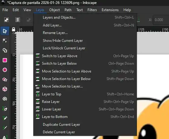
To overlap elements and organize complex designs, we use the Layers menu. This panel is essential for your workflow and allows you to:
Add and Delete:Create new layers to separate different parts of your design or remove those you no longer need.
Stacking Order:Change the priority by dragging layers up or down.
Visibility:Hide or show layers to work on specific parts of your design.
Locking:Prevent accidental changes to a layer by locking it.
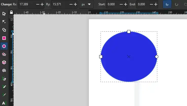
When we draw a shape, the top menu will display the option to set the dimensions as desired in pixels, milimeters or inches.
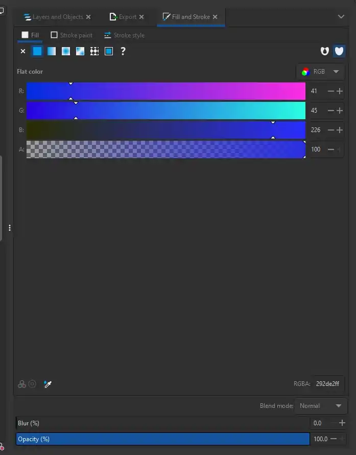
Within this menu, you can customize the appearance of any selected object by using the Fill tab to change the solid color, the Stroke paint tab allows you to choose the color of the object's border, while the Stroke style tab lets you adjust the thickness or size of the outline and select between solid, dotted, or dashed lines.
Trace Bitmap
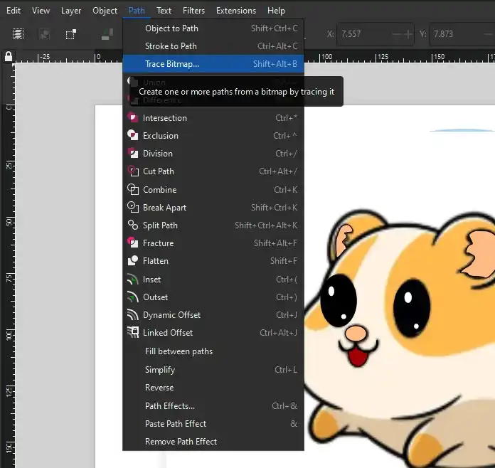
The Trace Bitmap function within the Path menu is used to convert pixel-based images, such as a JPG or PNG. This tool is essential for taking a hand-drawn sketch or a downloaded logo and converting it into clean lines and shapes.
To do this, you must go to Path, then select Trace Bitmap, and once the Trace Bitmap menu opens, simply press Apply.
My logo
Applying these Inkscape fundamentals, I designed the logo for my final project using the tools and techniques described earlier.
Export
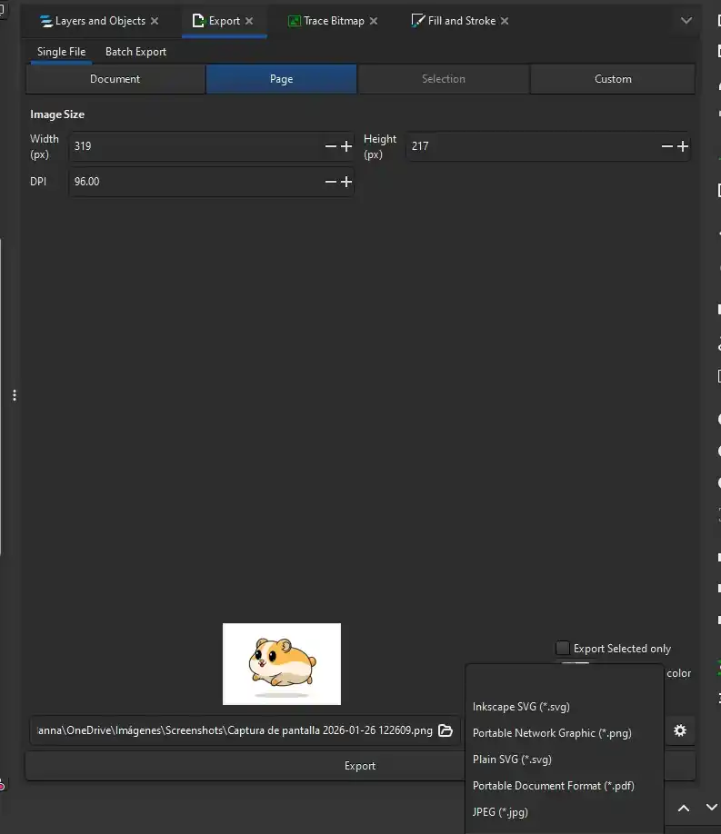
Once my logo was finished, I followed these steps to export it:
Go to the File menu.
Select Export.
A menu will open with all the export settings.
Select the location and the file type you want (SVG,PNG,PDF).
It is a free digital drawing and painting application for touch devices (iPad, Windows, iPhone) that combines live brushes (realistic watercolors and oils), pixel brushes, and vector brushes. It allows artists to create, animate, and share art in the cloud
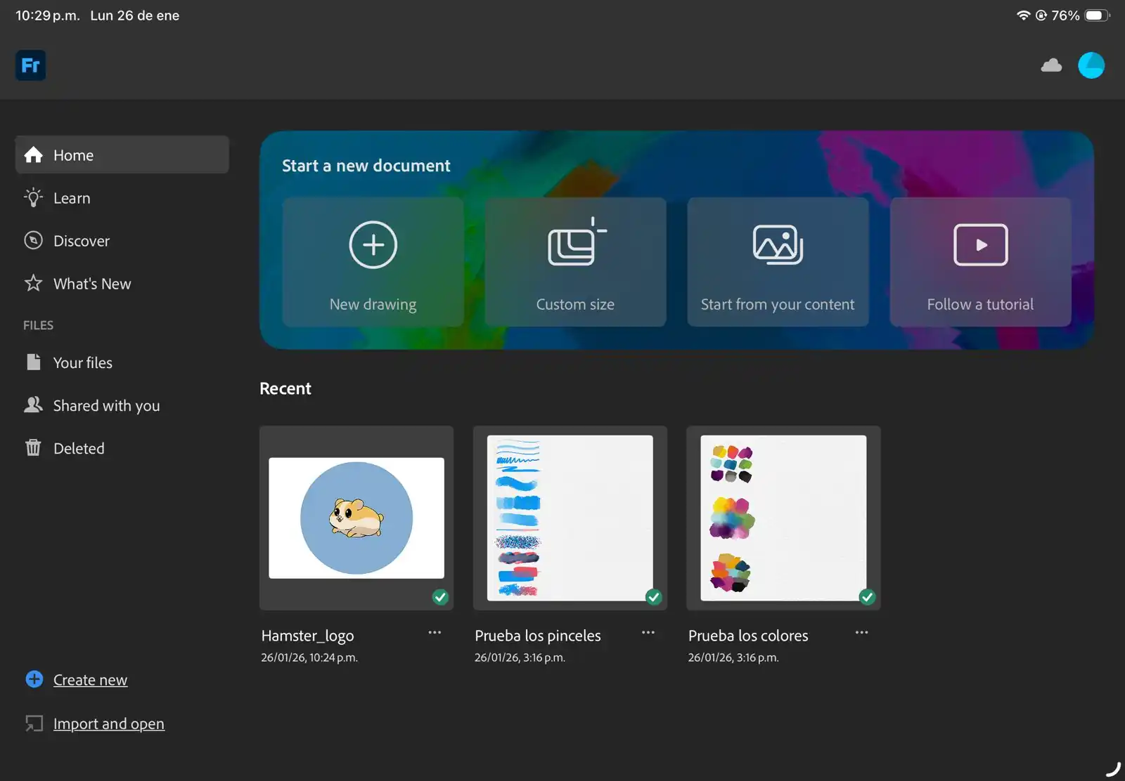
The main page of this application is the following; here you can choose between opening a tutorial on how to use the app, starting a new drawing, or opening an image you already have saved.
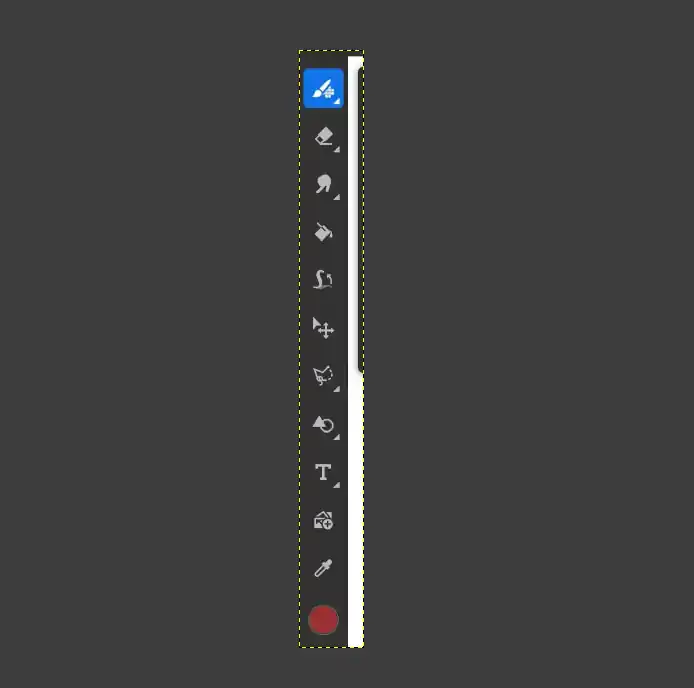
Our drawing area is flanked by different tool menus:
Brushes:These are brushes for painting in a traditional way, ideal for textures and shading.
Eraser:Used to remove parts of your drawing.
Selection Tool:This is used to outline a part of your drawing to move, scale, or apply color changes only to that specific area.
Transform:The arrow cross icon is used to move, rotate, or resize your layers or selected elements.
Paint Bucket:To quickly fill closed areas with a solid color.
Eyedropper:To select an exact color that is already on your canvas.
Text (T):To add typography to your design.
Insert Image:The icon with the '+' symbol is used to import photos or external references for tracing or editing."
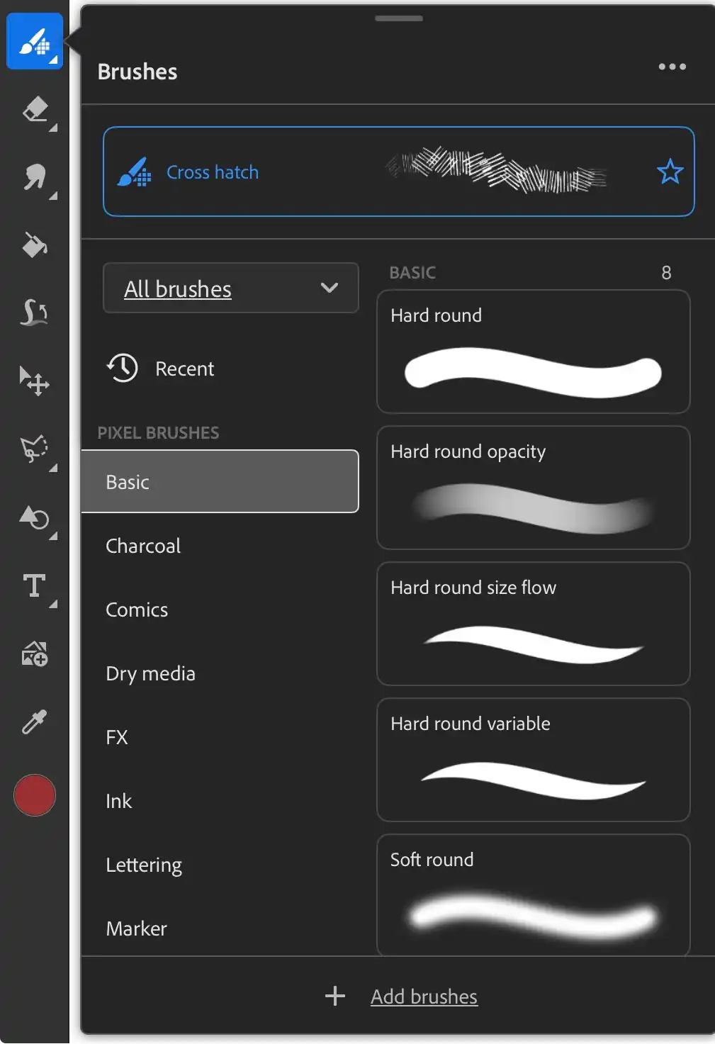
Brushes
When the brush tool is selected, this menu opens to give you full control over your strokes. It organizes brushes into categories like Basic, Charcoal, and Ink. You can see a preview of each brush style.
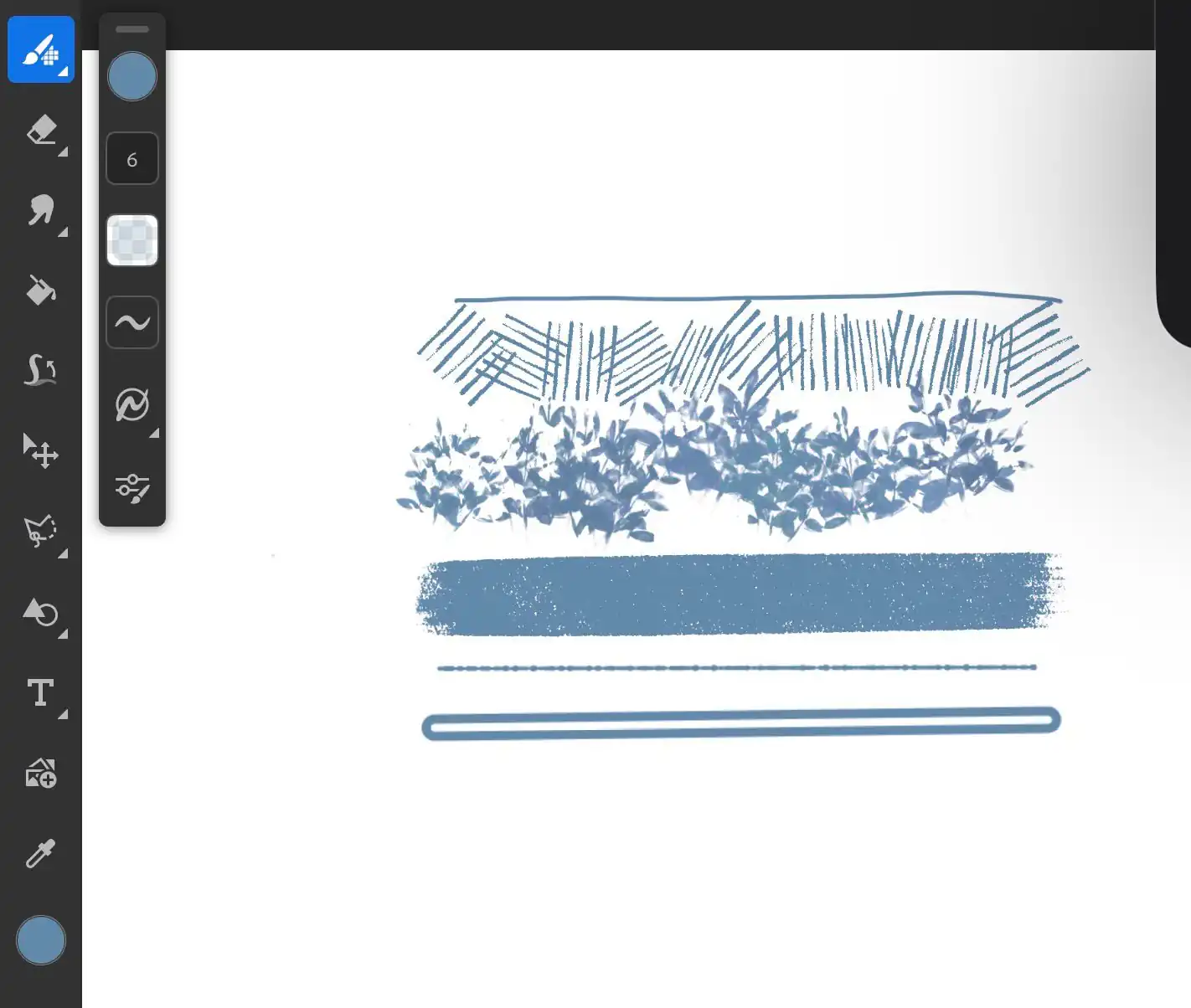
This is an example of how some brushes look; they have very different styles so that you can use them for many different purposes.
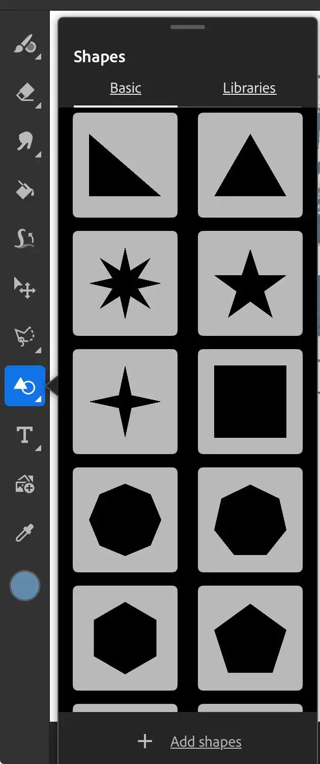
By expanding the shapes menu, we can see all the different options available for us to use.
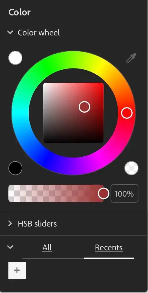
With this option, we can change the color of the elements and customize the design's aesthetics.
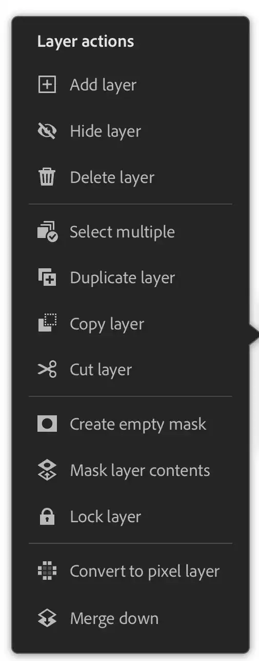
The Layer Actions menu is very useful for keeping our design organized. It allows you to add or delete layers, hide them to check your progress, or lock them to prevent accidental changes. You can also duplicate elements, use masks for non-destructive editing, or merge layers to simplify your project.
My logo
Using these fundamental tools, I began the design process for my logo in Adobe Fresco.
Final Result
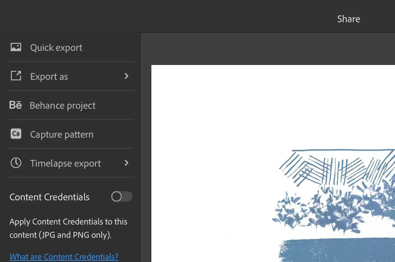
To export our image, we go to the Share menu located at the top of our drawing area, then select Export as to choose the location and the format in which we want to export it.
To create my logo, the 2D program I liked most was Adobe Fresco. I found it much easier to trace the lines and apply different colors, which gave the hamster more depth and a better tonal range compared to the version I made in Inkscape
Regarding the 3D design of my hamster base, I enjoyed using both programs; they are easy to learn and share many similarities. However, I would choose SOLIDWORKS because it offers a wider range of tools, such as simulation features and advanced rendering. I believe SOLIDWORKS allows for better testing of a part's functionality.
SOLIDWORKS RENDER
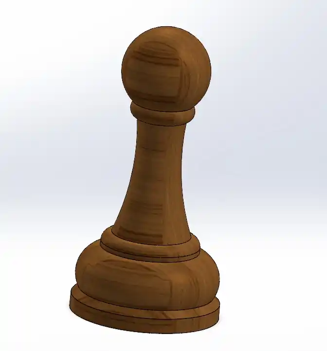
To use the rendering tool in Solid, I created a chess piece.
I followed these steps:
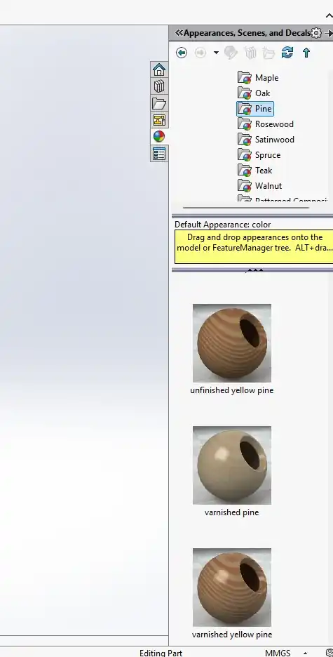
After finishing your part, go to the Appearances tab on the right side. Select the desired appearance and drag it directly onto your model.
Figure 01. Render interface
This is how my part looked before the rendering process.
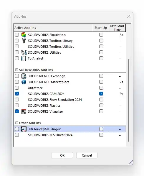
Figure 02. Render environment selection
At the top of the Solid tab, select Add-Ins and enable SOLIDWORKS Visualize. Wait a moment, and the SOLIDWORKS Visualize option will appear in your main menu.
Figure 03. Render material selection
Open the extension and select Export Simple. After a short wait, a new window will open.
Figure 04. Render lighting settings
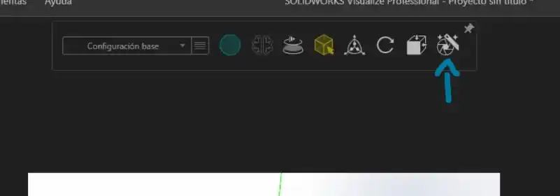
In the new SOLIDWORKS Visualize window, you will see a toolbar menu at the top.
This menu allows you to modify various rendering aspects, such as quality, camera view, and dimensions.
To export your image, click on the Output Tools icon (the camera/render icon) on the right side.
Figure 05. Render camera settings
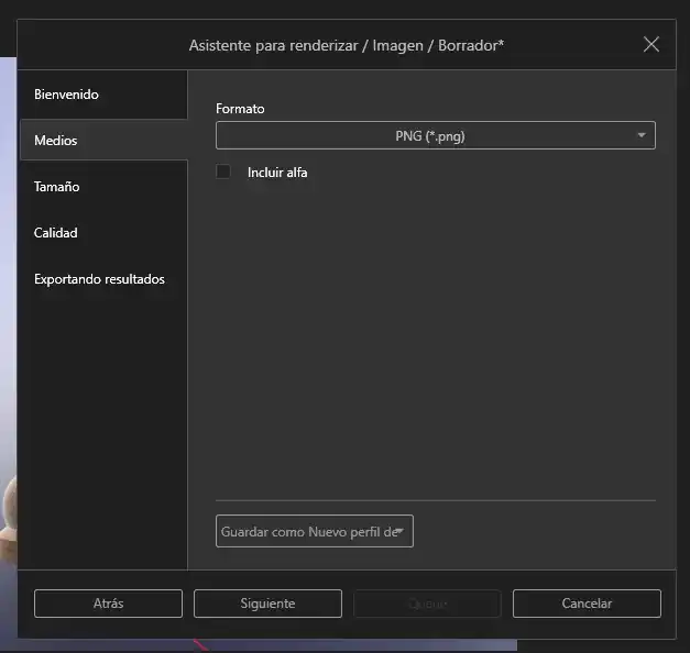
In this final menu, select your preferred quality, size, and file format. Lastly, choose the destination folder where you want to save your result.
Figure 05. Render camera settings
Render Result.
Figure 07. Render result
Compressing images
To compress the images I used to report this week I used GIMP, what must be done is the following:
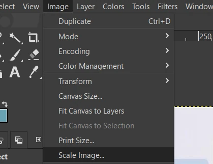
Open the program and open our image.
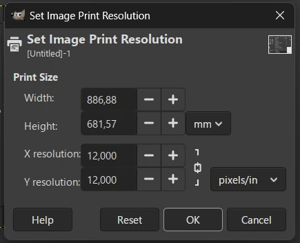
Go to the Image tab and then to Print Size.
Figure 01. GIMP interface
In this menu we must lower the resolution in X and Y.
Figure 02. GIMP Print Size menu
Export the image as .webp.
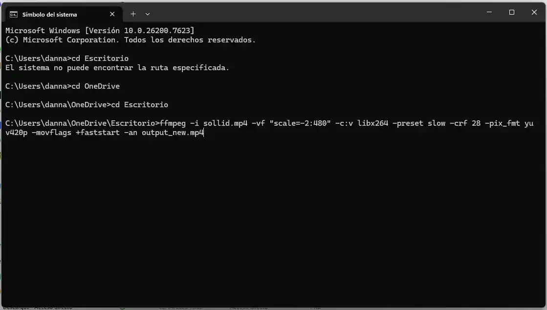
Compressing videos
To compress my videos, I used FFmpeg. After installing it on my computer, I ran the following command in the terminal to compress my file. Make sure you are in the same directory where your video is located before running the command.