Complete Machine Characterization
In this group assignment, we analyzed the performance of our fabrication tools by integrating a complete functional system. Our team focused on the synergy between electronics and complex mechanics, using a custom-designed robotic claw as the primary test subject for machine precision.
Technical highlights & contributions:
- Claw Assembly & Integration: We developed a fully functional robotic claw, serving as a benchmark to test the machine's ability to handle intricate mechanical parts and precise clearances.
- Vertical Displacement Mechanism: A core part of our work involved implementing the up-and-down (lead screw) system, allowing us to characterize vertical axis stability and torque requirements during operation.
- System-Wide Calibration: We used the integration of the claw and lifting mechanism to define the design rules for high-load components, ensuring that our electronics could reliably control complex mechanical movements.
- Process Documentation: We standardized the workflow for multi-part assemblies, from the initial CNC milling of structural plates to the final calibration of the motion control parameters.
Machine Design - Assignment:
For the Machine Design assignment, our team collaborated to build a fully functional, classic Arcade Claw Machine. This project required the seamless integration of multi-axis kinematics, microcontroller programming, and structural fabrication to create an automated system. Within this group effort, my primary responsibility was the conceptualization, mechanical design, and assembly of the system's core end effector: The Claw Mechanism.
Designing the claw presented a unique set of mechanical challenges. It needed to be lightweight to avoid stressing the gantry's Z-axis, yet robust enough to maintain a reliable grip on the plush toys. The mechanism relies on a system of linkages driven by a central actuator, converting rotational motion into the linear actuation required to open and close the prongs synchronously. This section documents my process from the initial CAD kinematics to the physical fabrication and testing of the claw.
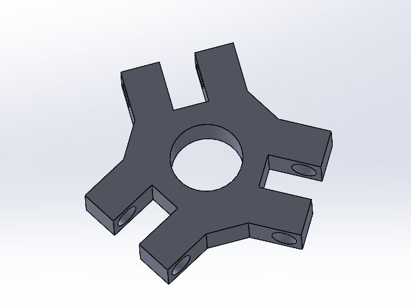
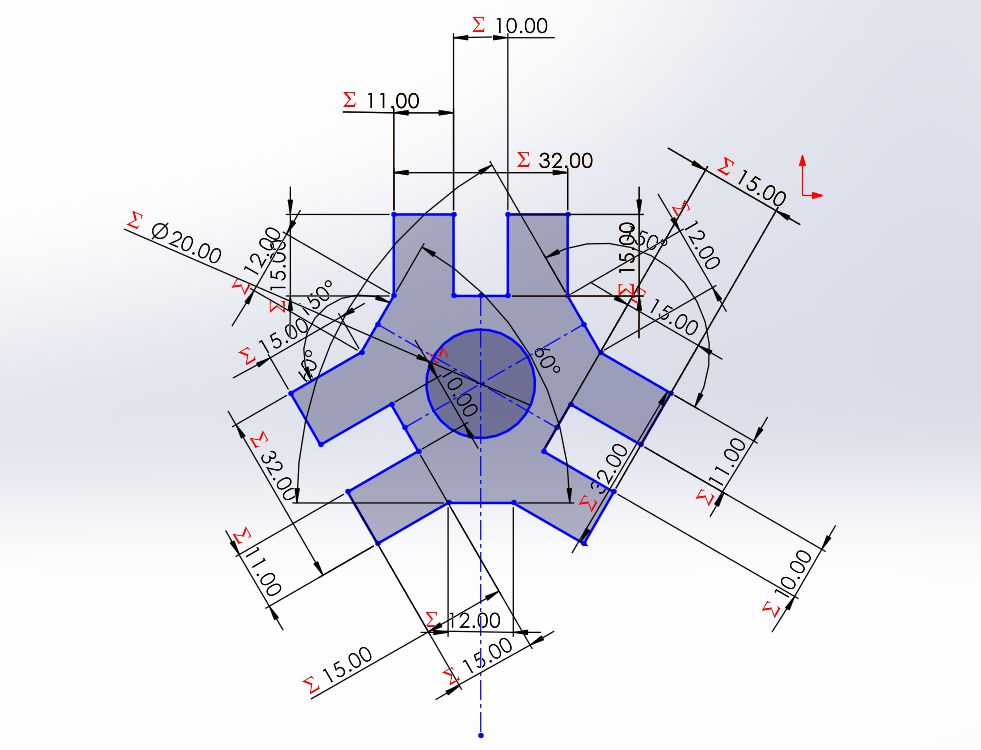
Mobile Base: Rotational to Linear Conversion
The core of the claw's motion is the mobile triangular base. This component acts as the mechanical interface that translates the actuator's energy into vertical displacement. It features a high-precision central bore designed to house a drive nut; as the central lead screw rotates, the nut (and consequently the entire base) is forced to move up or down. This linear travel is the primary driver that pulls or pushes the linkages to actuate the claw's prongs.
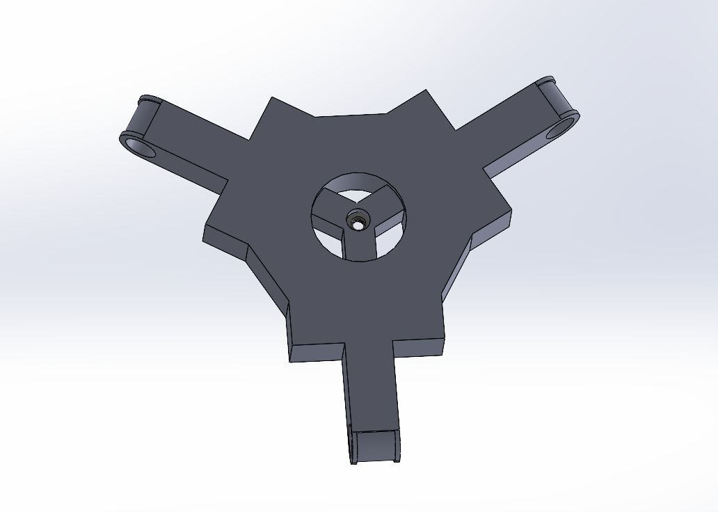
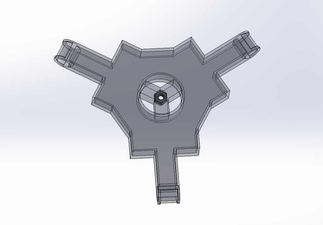
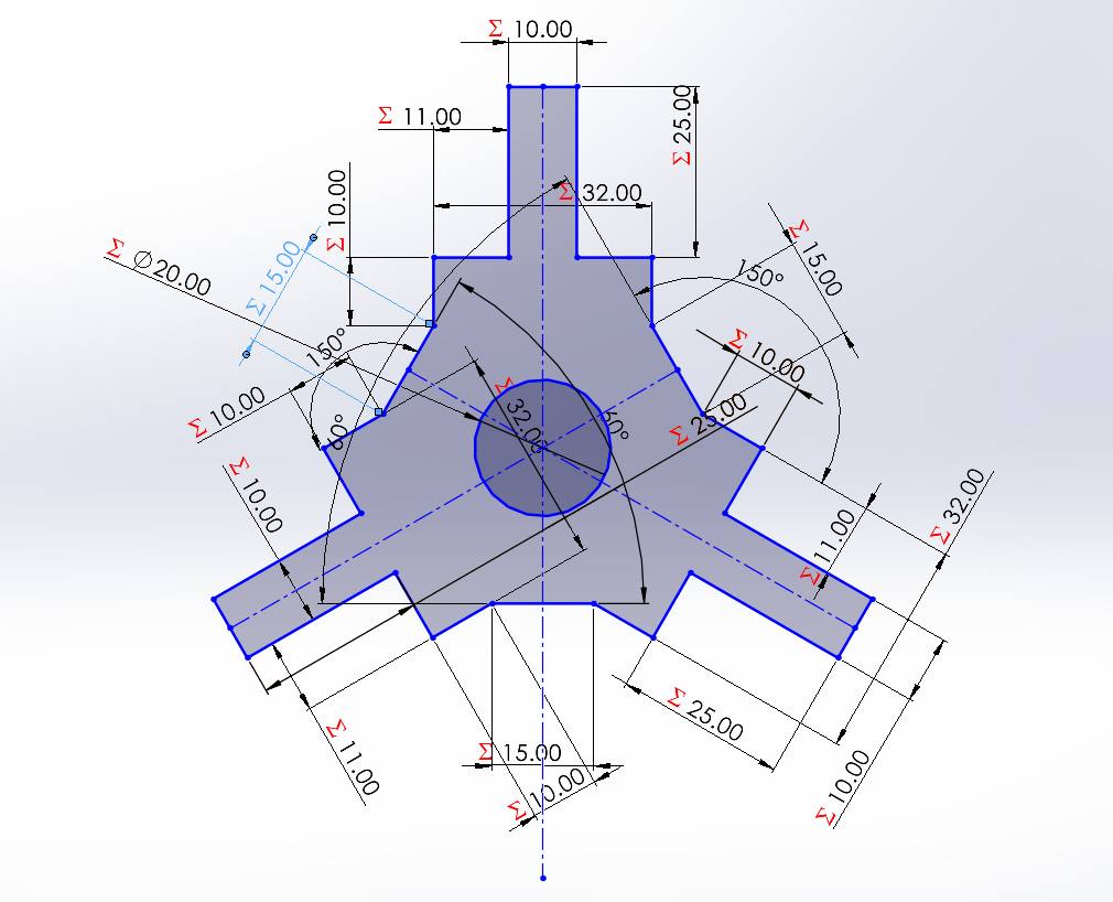
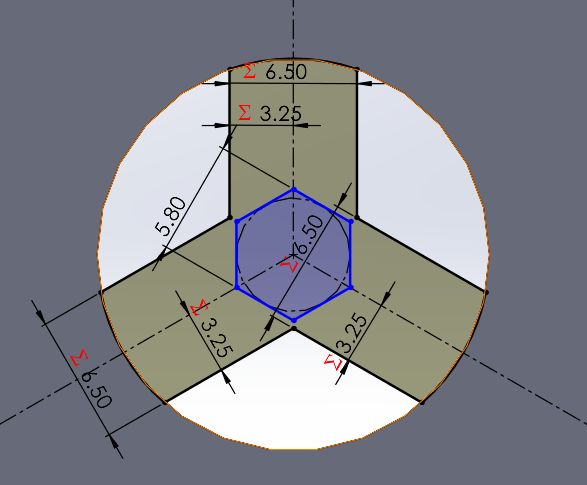
To ensure industrial-grade precision and compatibility with standard hardware, the 3D model for the internal hex nut was sourced from McMaster-Carr. This allowed for an exact fit within the mobile base's housing, maintaining the self-locking properties of the screw-driven system. The triangular symmetry ensures that the motion is transmitted equally to all three arms, maintaining a centered and balanced grip during operation.
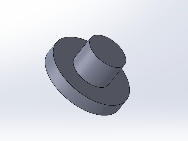
Fixed Lower Base: Alignment and Stability
The second key component is the fixed lower base. Unlike the mobile unit, this part remains stationary and acts as the structural anchor for the mechanical assembly. Its primary feature is a precision-engineered central bore that houses a guiding tube. This tube ensures that the vertical travel of the lead screw and the mobile base remains perfectly linear, preventing any lateral tilting or mechanical binding during the gripping cycle.
A critical design detail is that this fixed base is smaller in diameter than the mobile base. This size difference is intentional to ensure the proper mechanical clearance for the claw's prongs. By reducing the footprint of this lower anchor, the linkages can achieve a wider range of motion, allowing the claws to open fully without physical interference, which is essential for capturing larger objects during the machine's operation.
Central Guide Tube: Constraints and Anti-Rotation
The central guide tube is the backbone of the claw's structural integrity, designed with specific mechanical constraints to manage the movement of all other parts. The main body of the tube has a diameter of 19.5mm. At the bottom, it features a cap with a 14.5mm center hole and a physical stopper; the fixed base is sandwiched perfectly between these two elements to ensure zero vertical play. Higher up, a secondary stopper is placed—both stoppers feature a diameter of 29.5mm—to define the maximum travel limit for the mobile base.
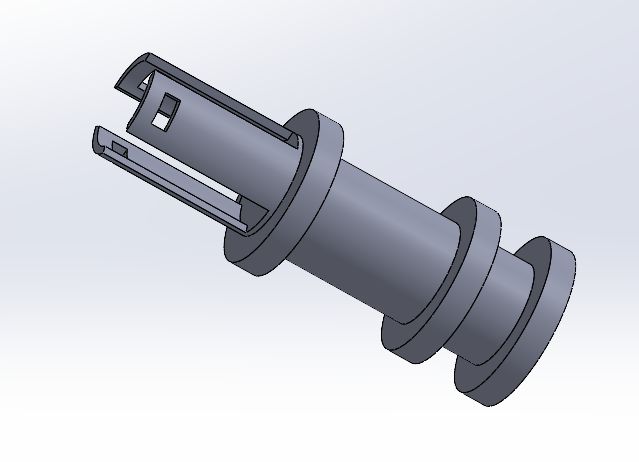
To ensure the mobile base only moves linearly, the tube incorporates anti-rotation tabs. These tabs, measuring 6mm in width and 3mm in height, interlock with the mobile base to physically block any rotational force from the lead screw. This design defines a precise vertical travel range of 29mm between the stoppers, forcing the mechanism to translate strictly up and down. Finally, the top of the tube is designed with mounting tabs that anchor the entire assembly to the motor housing, aligning the actuator's shaft perfectly with the internal screw system.
Actuator Assembly: Motor-to-Screw Coupling
The mechanical power of the claw is generated by a Pololu Micro Metal Gearmotor. To translate its rotation into the linear motion required by the mobile base, I designed a custom middle coupler. This component is engineered with a dual-interface geometry: one end is a press-fit socket designed to "trap" and secure a Socket Head M3 Screw from McMaster-Carr, while the other perfectly matches the motor's D-shaft profile.


To finalize the assembly, a fixed upper housing (tapa superior) was designed to encase the motor and coupler. This part serves two vital functions: it provides a rigid structural support that prevents the motor from wobbling under load, and it features locking tabs specifically designed to interlock with the top of the central guide tube. This snap-fit or bolt-on connection ensures that the entire drive train is concentric and securely anchored to the main structural body of the claw.
Claw Prongs: Tri-Symmetric Gripping System
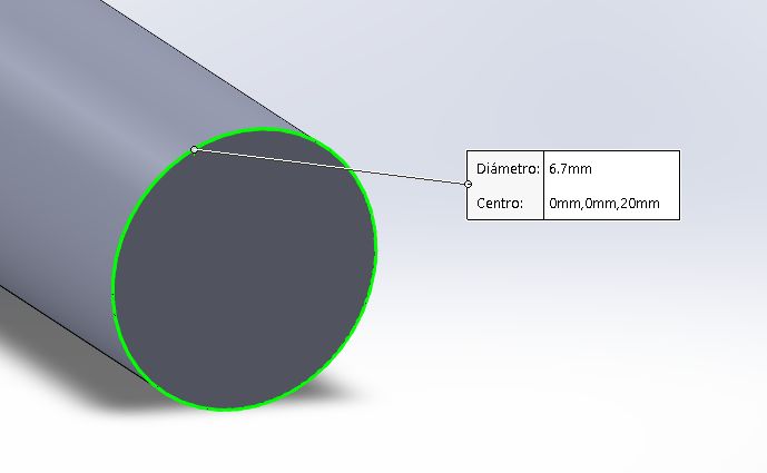
The final gripping action is performed by three identical claw prongs, each strategically mounted to the corners of the triangular bases. To enable smooth movement, I used small hollow tubes as pivot joints with a standardized diameter of 6.7mm. These pins act as axes that allow the prongs to rotate freely but securely. Due to this mechanical linkage, when the mobile base moves downward, it forces the prongs to pivot inward, effectively closing the claw and securing the object.
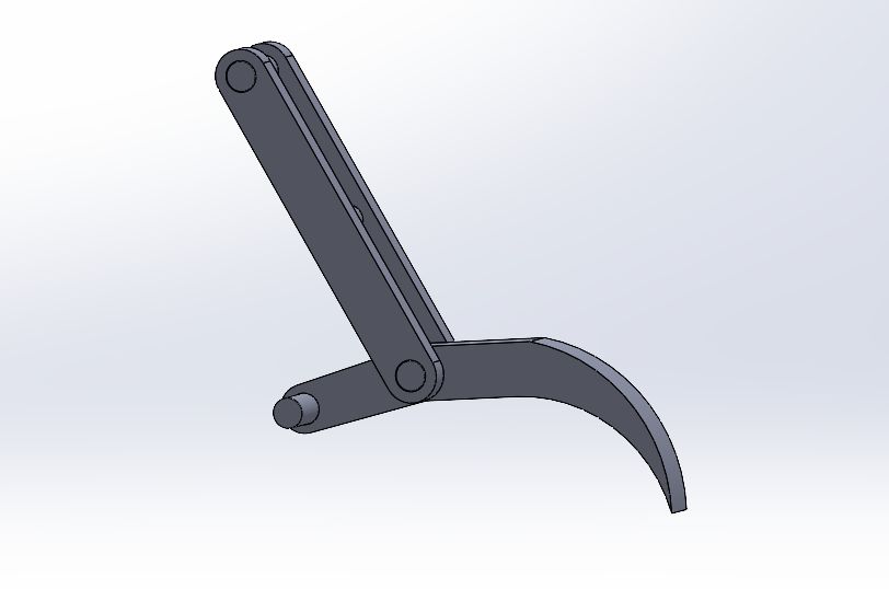
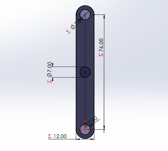
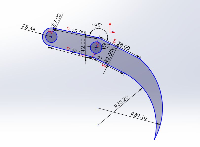
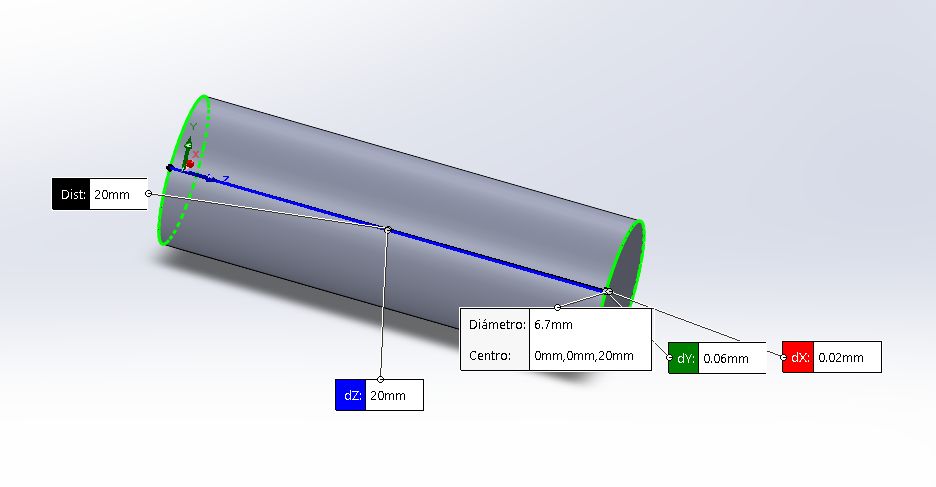
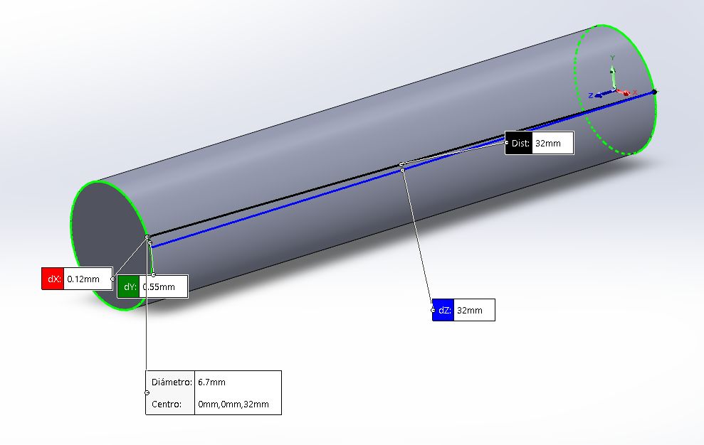
The assembly utilizes joints of varying lengths to accommodate the mechanical clearance: the claw-to-support and mobile base-to-support joints are 20mm in length, while the fixed base-to-claw joints are 32mm long. By utilizing this tri-lateral symmetry, the claw achieves a much more stable grip than a standard two-prong design. The mechanical advantage provided by the linkages ensures that once the prongs rotate into the closed position, they exert a consistent pressure, minimizing the risk of the prize slipping during the Z-axis lift.
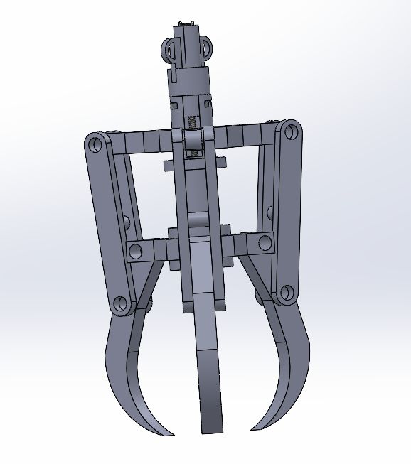
Full Assembly: The Final Claw Mechanism
The final assembly integrates all the components previously described into a synchronized robotic end effector. By combining the high-torque output of the Pololu gearmotor with the precision of the lead screw and the structural stability of the central guide tube, the mechanism achieves a smooth and reliable gripping cycle.
To verify the kinematic behavior of the design, I created a short animation. This video demonstrates the synchronization between the screw's rotation and the linear displacement of the mobile base, which ultimately triggers the opening and closing of the prongs:
For a more detailed inspection of the internal parts, clearances, and the assembly hierarchy, you can explore the interactive 3D model below:
This final verification step ensures that the CAD clearances translate correctly to the physical world, resulting in a robust claw ready for integration into the arcade machine gantry.
Functional Testing and Firmware Validation
To finalize the mechanical characterization, I developed a specific control script to validate the linear travel required for the gripping cycle. The following code utilizes the TB6612FNG driver to manage the motor's direction and speed, ensuring that the self-locking properties of the system are maintained through active braking after each movement:
const int AIN1 = 8;
const int AIN2 = 7;
const int PWMA = 9;
const int STBY = 10;

const long tiemposube = 1300;
const long tiempobaja = 1600;

void setup() {
  pinMode(AIN1, OUTPUT);
  pinMode(AIN2, OUTPUT);
  pinMode(PWMA, OUTPUT);

  digitalWrite(STBY, HIGH);

  Serial.begin(9600);
  Serial.println("=== CONTROL GARRA M3 (11mm) ===");
  Serial.println("Escribe '1' para SUBIR");
  Serial.println("Escribe '2' para BAJAR");
}

void loop() {
  if (Serial.available() > 0) {
    char seleccion = Serial.read();

    while(Serial.available() > 0) { Serial.read(); }

    if (seleccion == '1') {
      Serial.println("SUBIENDO 11mm...");
      moverMotor(true, tiemposube);
    }
    else if (seleccion == '2') {
      Serial.println("BAJANDO 11mm...");
      moverMotor(false, tiempobaja);
    }
    Serial.println("Esperando comando (1 o 2)...");
  }
}

void moverMotor(bool subir, long ms) {
  if (subir) {
    digitalWrite(AIN1, LOW);
    digitalWrite(AIN2, HIGH);
    analogWrite(PWMA, 255);
  } else {
    digitalWrite(AIN1, HIGH);
    digitalWrite(AIN2, LOW);
    analogWrite(PWMA, 200);
  }

  delay(ms);

  digitalWrite(AIN1, HIGH);
  digitalWrite(AIN2, HIGH);
  analogWrite(PWMA, 0);

  Serial.println("Movimiento finalizado.");
}
Once the code was uploaded, I conducted a physical test to verify the movement. The following video demonstrates the successful opening and closing cycle, proving that the mechanism operates smoothly without binding:
This milestone confirms that the anti-rotation tabs and the custom-fit M3 hex nut provide enough torque to actuate the three prongs simultaneously, marking the completion of the mechanical design phase.
Z-Axis Motion: Vertical Displacement System
To enable the vertical travel of the claw, I adapted a mechanical structure originally designed by Antonio Martínez. This component serves as the main gantry interface and was specifically modified to house a high-torque Yellow DC Motor, which provides the necessary power to lift the weight of the assembly.
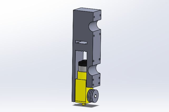
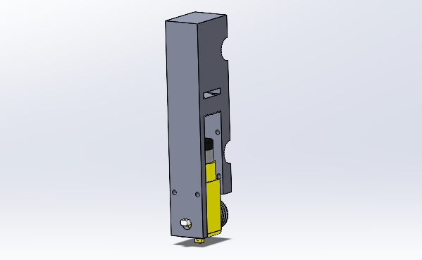
The system utilizes a dual-pulley mechanism mounted on the motor's output shaft. Two high-strength threads are anchored to these pulleys, acting as the hoisting lines for the claw. This configuration ensures a balanced lift, minimizing tilting and ensuring that the claw remains perfectly vertical during its descent into the prize pit and its subsequent ascent with a captured object.
Motor Driver Interface: TB6612FNG Carrier Board
To centralize the connection between the Raspberry Pi Pico 2 and the two actuators (Pololu and Yellow DC motor), I designed a minimalist interface PCB. This board serves as a dedicated carrier for the TB6612FNG dual motor driver, featuring external male headers that allow for quick "plug-and-play" connectivity between the logic controller and the power outputs.
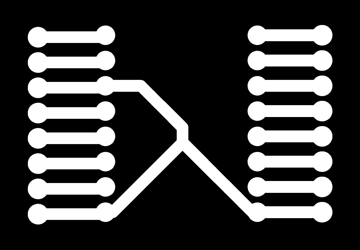
The design is intentionally simple, focusing on maximizing trace width for power delivery while maintaining a compact footprint. By housing the driver in the center and surrounding it with accessible male pin headers, I eliminated the need for messy point-to-point wiring. This custom board ensures a stable electrical connection, preventing accidental disconnections during the mechanical stress of the claw's vertical and gripping movements.
Integrated System Control: Raspberry Pi Pico 2
To orchestrate the complete cycle of the machine, I used the Raspberry Pi Pico 2 as the main controller. This script manages the synchronization between the Z-axis (Yellow DC motor) and the claw mechanism (Pololu motor). The routine is triggered by a physical button and follows a precise sequence: descending the structure, waiting, closing the claw, ascending, and finally releasing the object.
const int AIN1 = 8;
const int AIN2 = 9;
const int PWMA = 10;

const int BIN1 = 11;
const int BIN2 = 12;
const int PWMB = 13;

const int STBY = 14;
const int pinBoton = 15;

const long amarilloBaja = 1400;
const long amarilloSube = 1800;
const long poluluCerrar  = 1550;
const long poluluAbrir   = 1500;

const int potenciaAmarillo = 100;
const int potenciaPolulu   = 255;

void setup() {
  pinMode(pinBoton, INPUT_PULLUP);

  pinMode(AIN1, OUTPUT);
  pinMode(AIN2, OUTPUT);
  pinMode(PWMA, OUTPUT);
  pinMode(BIN1, OUTPUT);
  pinMode(BIN2, OUTPUT);
  pinMode(PWMB, OUTPUT);
  pinMode(STBY, OUTPUT);

  digitalWrite(STBY, HIGH);

  Serial.begin(115200);
  while (!Serial && millis() < 4000);

  Serial.println("\n=== PICO 2 CONFIGURADA (PINES 8-15) ===");
  Serial.println("Esperando pulsacion en GPIO 15...");
}

void loop() {
  if (digitalRead(pinBoton) == LOW) {
    delay(50);

    ejecutarRutina();

    while(digitalRead(pinBoton) == LOW) { delay(10); }
    Serial.println("\nSistema listo de nuevo. Presiona el boton...");
  }
}

void ejecutarRutina() {
  Serial.println(">>> RUTINA EN MARCHA...");

  Serial.println("1. Bajando estructura (Amarillo)...");
  moverAmarillo(false, amarilloBaja);

  Serial.println("2. ESPERA: 2 segundos abajo...");
  delay(2000);

  Serial.println("3. Cerrando garra (Polulu)...");
  moverPolulu(true, poluluCerrar);
  delay(500);

  Serial.println("4. Subiendo estructura (Amarillo)...");
  moverAmarillo(true, amarilloSube);

  Serial.println("5. ESPERA: 3 segundos arriba...");
  delay(3000);

  Serial.println("6. Apertura final (Polulu)...");
  moverPolulu(false, poluluAbrir);

  Serial.println("=== RUTINA COMPLETADA ===");
}

void moverAmarillo(bool sube, long ms) {
  digitalWrite(AIN1, sube ? LOW : HIGH);
  digitalWrite(AIN2, sube ? HIGH : LOW);
  analogWrite(PWMA, potenciaAmarillo);
  delay(ms);
  frenarMotor(true);
}

void moverPolulu(bool sube, long ms) {
  digitalWrite(BIN1, sube ? LOW : HIGH);
  digitalWrite(BIN2, sube ? HIGH : LOW);
  analogWrite(PWMB, potenciaPolulu);
  delay(ms);
  frenarMotor(false);
}

void frenarMotor(bool esAmarillo) {
  if (esAmarillo) {
    digitalWrite(AIN1, HIGH); digitalWrite(AIN2, HIGH);
    analogWrite(PWMA, 0);
  } else {
    digitalWrite(BIN1, HIGH); digitalWrite(BIN2, HIGH);
    analogWrite(PWMB, 0);
  }
}
With the firmware successfully handling the timing and power distribution for both motors, I performed a full cycle test. In the following video, you can observe the entire process as the gantry lowers the claw, secures a piece of candy, and returns to the starting position before releasing it:
This integration confirms that the Raspberry Pi Pico 2 is capable of managing the complex interactions between the DC motors, providing a solid foundation for the final automation of the arcade machine.
This mechanical design represents the successful transformation of rotational motion into a functional tri-symmetric robotic claw for our group project. Beyond the structural integration, the primary challenges involved precision engineering of tolerances to ensure smooth movement without mechanical binding and the rigorous empirical testing required to calibrate exact timings for the ascending, descending, opening, and closing cycles. By synchronizing the Raspberry Pi Pico 2 with both drive systems, I achieved a reliable and repeatable actuator that effectively bridges the gap between digital CAD modeling and physical machine performance.
Files
├── Claw
│   └── CNC_Stl
│       ├── AcoploTor.STL
│       ├── BaseCentro.STL
│       ├── BaseSuperior.STL
│       ├── Garra.STL
│       ├── GarraconMotor.STL
│       ├── MotorSubida.STL
│       ├── ParteSubida.STL
│       ├── PoleitaAm.STL
│       ├── Soportes.STL
│       ├── TapaBaja.STL
│       ├── TapaSuperior.STL
│       ├── TuboEnMedio.STL
│       ├── Uniones.STL
│       └── UnionesBajas.STL
└── MotorsPcb
    ├── CNC.kicad_pcb
    ├── CNC.kicad_pro
    ├── CNC.kicad_sch
    ├── Cuts
    │   ├── Cutout.rml
    │   ├── postMessage.png.rml
    │   └── Traces.rml
    ├── Gerbrs
    │   ├── CNC-B_Cu.gbr
    │   ├── CNC-B_Mask.gbr
    │   ├── CNC-B_Paste.gbr
    │   ├── CNC-B_Silkscreen.gbr
    │   ├── CNC-Edge_Cuts.gbr
    │   ├── CNC-F_Cu.gbr
    │   ├── CNC-F_Mask.gbr
    │   ├── CNC-F_Paste.gbr
    │   ├── CNC-F_Silkscreen.gbr
    │   ├── CNC-job.gbrjob
    │   ├── CNC-NPTH.drl
    │   └── CNC-PTH.drl
    └── Png
        ├── drills_toplayer_1.png
        ├── outline_toplayer_2.png
        └── traces_toplayer_0.png