Project description
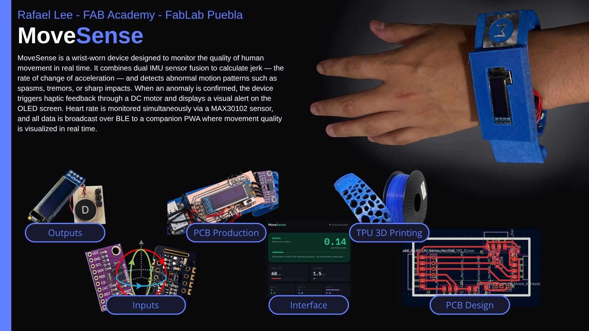
My project consist on the development of a Wearable device that monitors movement quality, to focus on the detection of early changes in motor control that are associated with mucular disftrophy with a system that analyzes motion pattern to identify the variability, smoothness and range, that serve as indicaions of functional deterioration
Potential Applications
The system is designed to address several real-world scenarios where continuous movement quality monitoring provides clinical or performance value.
| Application | How the device helps |
|---|---|
| Physical rehabilitation | Monitors movement quality during recovery exercises, alerting when compensatory or unsafe motion patterns occur. |
| Neuromotor conditions | Detects and quantifies tremors or involuntary spasms in patients with conditions such as Parkinson's disease or muscular dystrophy. |
| Sports performance | Identifies erratic or asymmetric movement patterns in athletes that may indicate fatigue or injury risk before symptoms appear. |
| Early deterioration detection | Provides a longitudinal baseline of motor control quality, enabling clinicians to detect progressive functional decline over time. |
Project Concept & Design Sketch
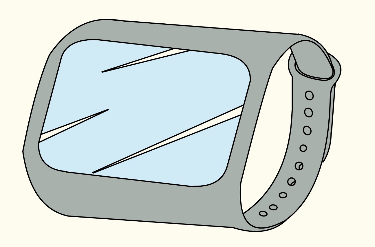
The design of the wearable device focuses on ergonomics and portability, as it is intended for long-term monitoring of patients with neuromuscular conditions. The system is conceived as a modular bracelet located on the wrist or forearm, a strategic position to capture the most significant data regarding arm tremors, range of motion, and movement smoothness.

As illustrated in the conceptual sketch, the device integrates an Inertial Measurement Unit (IMU) containing an accelerometer and a gyroscope. This sensor captures raw data of acceleration, angular velocity, and time, which are then processed through the onboard firmware. The signal processing layer focuses on three main pillars: calculating the Range of Motion, analyzing Movement Variability, and measuring Movement Smoothness through jerk analysis.
The system is designed to be highly functional and user-centric. The output is simplified into two primary feedback methods: a numerical score ranging from 0 to 100, representing the progressive functional deterioration, and a visual "Traffic Light" system. This color-coded feedback, combined with haptic vibration and LED indicators, provides the user with early warnings and preventive alerts regarding their motor control status.
This "closed-loop" design ensures that the device is not just a data logger, but an active monitoring tool. By housing the power management, the processing unit, and the feedback interface within a compact wearable form factor, the bracelet becomes an autonomous unit ready for real-world clinical assessment.
Project Concept & Design Evolution
The system is conceived as a modular bracelet strategic to capturing significant data regarding arm tremors, range of motion, and movement smoothness. The initial functional logic, as defined in my very first rough sketch, centered on using the IMU to process Range of Motion, Movement Variability, and Smoothness, leading to a simple numerical score (0-100) and traffic light feedback system.
Building upon that initial logic, during Week 2, I advanced the concept by creating more detailed design representations. This iteration involved developing a specific visual form factor that transitions the theoretical device into a wearable product. These designs refine the aesthetics of the bracelet, defining the integration of the display and the overall look of the protective shell. You can explore the full computer-aided design process in the Week 2 documentation.
Simultaneously, I leveraged SolidWorks to develop a precise 3D model of the bracelet housing. This CAD iteration was crucial for defining the physical dimensions and component fit, establishing a foundation for future manufacturing. The resulting design features a robust yet streamlined casing that encapsulates the electronics and presents a clear visual interface for user feedback.
The transition from the very simple logical sketch to these detailed 3D representations highlights the early stages of product development, ensuring that the theoretical functional segments are grounded in a manufacturable and ergonomic hardware design.
Hardware Strategy & Motion Analysis
Following the electronics production path established in Week 4, the final device is powered by the Seeed Studio XIAO nRF52840 Sense. This microcontroller was selected for its integrated 6-axis IMU and its ability to handle complex data fusion. To achieve full 9-axis orientation tracking, I have integrated an external TLE493D 3D Magnetic Sensor via I2C. This combination allows for precise movement reconstruction, providing a stable reference to calculate movement quality.
Beyond motion, the bracelet incorporates a clinical dimension by using the MAX30102 Pulse Oximeter. This sensor enables the real-time acquisition of Heart Rate (BPM) and Blood Oxygenation (SpO2). To provide immediate feedback to the user, the system features an SH1106 OLED Display. This visual interface is programmed to show both the biometric data and the results of the motion analysis, creating a comprehensive health monitoring gateway on a flexible copper tape bus.
The primary metric for assessing "smoothness" is Jerk (the rate of change of acceleration). While acceleration measures speed changes, Jerk quantifies how abruptly those changes occur. In a medical context, smooth movement is characterized by low jerk values. Erratic or uncontrolled movements—often seen in motor control disorders—produce high jerk spikes. By visualizing these spikes alongside heart rate on the OLED, the device quantifies functional deterioration that might otherwise remain invisible.
Interactive Kinematics: Understanding Jerk
Use the dropdown below to simulate the difference between a healthy, smooth movement and an uncontrolled, jerky movement. Notice how sudden steps in Acceleration translate into massive spikes in the Jerk graph.
Using the 9-axis fusion (Accelerometer + Gyroscope + Magnetometer), the firmware will be able to filter out gravitational noise and focus strictly on the Dynamic Jerk produced by the user. This data will be the foundation for the 0-100 quality score and the traffic light feedback system described in the initial conceptual sketches.
Bill of Materials
Movement Quality Bracelet - Full Sensor Suite
| Component | Specification | Qty | Function |
|---|---|---|---|
| XIAO nRF52840 | Sense Version (Integrated IMU) | 01 | Controller |
| BNO08X | 3D Magnetic Sensor (I2C) | 01 | Magnetometer |
| MAX30102 | Pulse Oximeter & Heart-Rate | 01 | Biometric |
| SH1106 OLED | 1.3" Display (I2C) | 01 | Visualization |
| Vibration Motor | 3V Coreless Haptic Actuator | 01 | Feedback |
| Rigid Copper PCB | Custom Fabricated Board | 01 | Main Circuit |
| LiPo Battery | 3.7V 100mAh Rechargeable | 01 | Power |
| Housing | Flexible TPU / 3D Printed | 01 | Structure |
Interface
The MoveSense interface is a Progressive Web Application (PWA) built with plain HTML, CSS, and JavaScript — no frameworks, no build tools, no dependencies beyond a few hosted fonts and icons. It runs entirely in the browser and can be installed on any Android phone as a native-like app directly from Chrome. The interface currently operates in simulation mode, generating realistic IMU and heart rate data algorithmically to allow full testing of the dashboard, alert system, and history log before the physical wearable is ready. Once the XIAO nRF52840 firmware is finalized and the BLE GATT service is configured, activating live data requires changing only two UUID constants and one function call in index.html — the rest of the interface remains identical.
App Icon
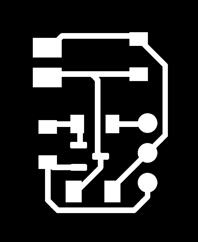
The PWA icon was generated programmatically using Python and the Pillow library. It displays a dark background with a teal circle and a stylized M mark, consistent with the dashboard's color palette. The icon is required in three sizes for full Android and iOS compatibility.
Deploying to GitHub Pages
The PWA is hosted using GitHub Pages, which provides free static hosting with HTTPS — a hard requirement for both the Service Worker (offline support) and the Web Bluetooth API (BLE connection). The full deployment is done through the GitHub web interface with no CLI or build step needed.
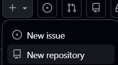
1. Create a new repository: Click the + button in the top navigation bar and select New repository from the dropdown menu.
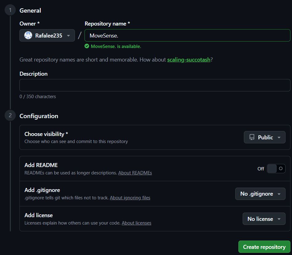
2. Name your repository: Under General, enter a name for your repository in the Repository name field. Set visibility to Public — this is required for free GitHub Pages hosting. Leave README, .gitignore, and license options untouched, then click Create repository.
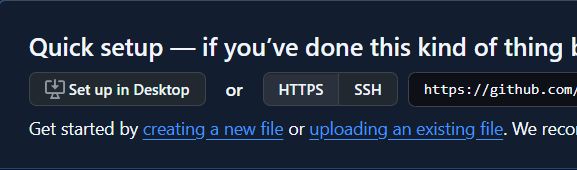
3. Upload your files: On the empty repository screen, click uploading an existing file to open the file upload interface.
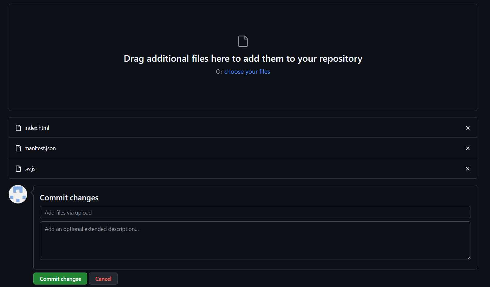
4. Drag and commit: Drag index.html, manifest.json, and sw.js into the upload area. Once all three files appear in the list, click Commit changes to save them to the repository.
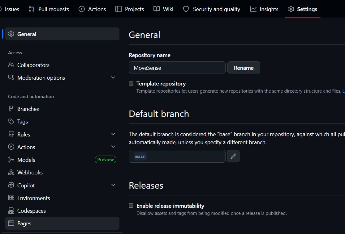
5. Go to Settings → Pages: In the repository top navigation, click Settings. In the left sidebar, scroll down and click Pages.
6. Configure deployment: Under Build and deployment, set Source to Deploy from a branch, select branch main and folder / (root), then click Save.

7. Your app is live: After 1–2 minutes, GitHub Pages generates a public HTTPS link. Open it in Chrome on your phone, tap the three-dot menu, and select Add to Home Screen to install MoveSense as a standalone app.

Project Structure
The entire application lives in three files and an icons folder. The Service Worker handles offline caching and push notifications. The manifest defines how the app appears when installed. The main HTML file contains all UI, logic, and the BLE connection layer in a single self-contained document.
| File | Role |
|---|---|
index.html |
Full UI, dashboard logic, BLE layer, simulation engine |
sw.js |
Service Worker — offline cache and push notifications |
manifest.json |
PWA metadata — name, theme color, icons, display mode |
icons/ |
App icons at 96×96, 192×192, and 512×512 px |
Service Worker — sw.js
Registers the app for offline use by caching the three core files on install. Also listens for postMessage calls from the main thread to fire native push notifications when an anomaly is detected, even if the app is running in the background.
const CACHE = 'movesense-v1';
const ASSETS = ['./', './index.html', './manifest.json'];

self.addEventListener('install', e => {
  e.waitUntil(caches.open(CACHE).then(c => c.addAll(ASSETS)));
  self.skipWaiting();
});

self.addEventListener('activate', e => {
  e.waitUntil(caches.keys().then(keys =>
    Promise.all(keys.filter(k => k !== CACHE).map(k => caches.delete(k)))
  ));
  self.clients.claim();
});

self.addEventListener('fetch', e => {
  e.respondWith(
    caches.match(e.request).then(r => r || fetch(e.request))
  );
});

self.addEventListener('message', e => {
  if (e.data?.type === 'NOTIFY') {
    const { title, body, score } = e.data;
    self.registration.showNotification(title, {
      body,
      icon: './icons/icon-192.png',
      badge: './icons/icon-96.png',
      tag: 'movesense-alert',
      renotify: true,
      data: { score },
      actions: [{ action: 'view', title: 'Open dashboard' }]
    });
  }
});

self.addEventListener('notificationclick', e => {
  e.notification.close();
  e.waitUntil(clients.matchAll({ type: 'window' }).then(cs => {
    if (cs.length) return cs[0].focus();
    return clients.openWindow('./');
  }));
});
PWA Manifest — manifest.json
Tells the browser how to present the app when installed: standalone display mode (no browser chrome), dark theme color matching the dashboard background, and the three icon sizes required for Android and iOS home screens.
{
  "name": "MoveSense",
  "short_name": "MoveSense",
  "description": "Real-time movement quality monitor",
  "start_url": "./index.html",
  "display": "standalone",
  "background_color": "#0c0e12",
  "theme_color": "#0c0e12",
  "orientation": "portrait",
  "icons": [
    { "src": "./icons/icon-96.png",  "sizes": "96x96",   "type": "image/png" },
    { "src": "./icons/icon-192.png", "sizes": "192x192", "type": "image/png", "purpose": "any maskable" },
    { "src": "./icons/icon-512.png", "sizes": "512x512", "type": "image/png", "purpose": "any maskable" }
  ]
}
Main Application — index.html
Contains the complete interface across three views — Connect, Live, and History — along with four self-contained modules: Nav handles view switching, Dashboard renders incoming sensor data, Hist manages the anomaly log and CSV export, and Notif controls push notification permissions and delivery. The SIM module generates synthetic data while the wearable is not yet connected. The BLE module wraps the Web Bluetooth API and will replace SIM once the XIAO firmware is ready — only the two UUID constants below need to be updated to match the GATT service defined on the device.
<!DOCTYPE html>
<html lang="en">
<head>
<meta charset="UTF-8">
<meta name="viewport" content="width=device-width, initial-scale=1, viewport-fit=cover">
<meta name="theme-color" content="#0c0e12">
<meta name="apple-mobile-web-app-capable" content="yes">
<meta name="apple-mobile-web-app-status-bar-style" content="black-translucent">
<meta name="apple-mobile-web-app-title" content="MoveSense">
<title>MoveSense</title>
<link rel="manifest" href="./manifest.json">
<link rel="apple-touch-icon" href="./icons/icon-192.png">
<link rel="stylesheet" href="https://cdn.jsdelivr.net/npm/@tabler/icons-webfont@2.44.0/tabler-icons.min.css">
<link rel="preconnect" href="https://fonts.googleapis.com">
<link rel="stylesheet" href="https://fonts.googleapis.com/css2?family=IBM+Plex+Mono:wght@400;600&family=DM+Sans:wght@300;400;500;600&display=swap">
</head>
<!--
  Full source: https://github.com/rafalee235/movesense

  To activate live BLE data from the XIAO, replace the two UUID
  constants inside the BLE object and remove the SIM.start() call:

  SERVICE_UUID: 'pendant',
  CHAR_UUID:    'pendant',

  The characteristic must notify a 24-byte ArrayBuffer:
  [ax, ay, az, jerk, hr, score] — 6 x Float32, little-endian.
-->
</html>
Simulation Mode vs. Live Mode
In its current state the app boots into simulation mode automatically. The SIM module generates three movement states — normal, moderate, and anomalous — each producing realistic accelerometer values, jerk RMS, heart rate, and anomaly score. When the XIAO is connected via BLE, the SIM module stops and BLE takes over, parsing a 24-byte ArrayBuffer broadcast by the device every 100 ms. The transition is seamless and requires no page reload.
| Mode | Data source | Anomaly score | Notifications |
|---|---|---|---|
| Simulation | Algorithmically generated | Randomized per state | Active (browser) |
| Live (XIAO) | BLE GATT characteristic | Edge Impulse model output | Active (Service Worker) |
Simulation Demo
The following video shows the PWA running in simulation mode, demonstrating the three movement states — Normal, Moderate, and Anomalous — along with the live dashboard, anomaly score, axes readout, and history log.
Switching to Live Data
Once the XIAO nRF52840 firmware is running and broadcasting over BLE, the interface switches from simulation to live mode automatically upon connection — no code changes required on the PWA side beyond the two UUID constants that must match the GATT service defined in the firmware. When connected, the simulation engine stops, the "Simulate movement" panel is hidden, and all dashboard values reflect real sensor readings streamed from the device every 20 ms.
The BLE characteristic sends a 24-byte packet containing six 32-bit floats in little-endian order: jerk magnitude, acceleration on each axis, and average heart rate. The anomaly score displayed in the dashboard is not sent by the device — it is computed in the browser by normalizing the incoming jerk value against the same 500 m/s³ threshold used in the firmware, mapping it to a 0–1 scale that drives the color states and alert logic.
| Byte offset | Value | Type |
|---|---|---|
| 0–3 | Jerk magnitude (m/s³) | Float32 LE |
| 4–7 | Acceleration X (m/s²) | Float32 LE |
| 8–11 | Acceleration Y (m/s²) | Float32 LE |
| 12–15 | Acceleration Z (m/s²) | Float32 LE |
| 16–19 | Heart rate (bpm) | Float32 LE |
Main Application — index.html
Contains the complete interface across three views — Connect, Live, and History — along with four self-contained modules: Nav handles view switching, Dashboard renders incoming sensor data, Hist manages the anomaly log and CSV export, and Notif controls push notification permissions and delivery. The SIM module generates synthetic data while the wearable is not connected. The BLE module wraps the Web Bluetooth API and replaces SIM automatically upon connection — only the two UUID constants below need to match the GATT service defined in the firmware.
<!-- Full source: https://github.com/rafalee235/MoveSense -->

<!--
  To activate live BLE data from the XIAO, the two UUID constants
  inside the BLE object must match the firmware exactly:

  SERVICE_UUID: '12345678-1234-1234-1234-123456789abc',
  CHAR_UUID:    '12345678-1234-1234-1234-123456789abd',

  The characteristic notifies a 24-byte ArrayBuffer:
  [jerkFinal, ax, ay, az, beatAvg] — 6 x Float32, little-endian.
  Anomaly score is computed in the browser by normalizing jerk to 0-1.
-->
Physical Development
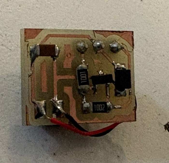
DC Motor Driver
Similar to what was done in week 10, and based on the same components, I was able to make a smaller version of that same board.
Band Design
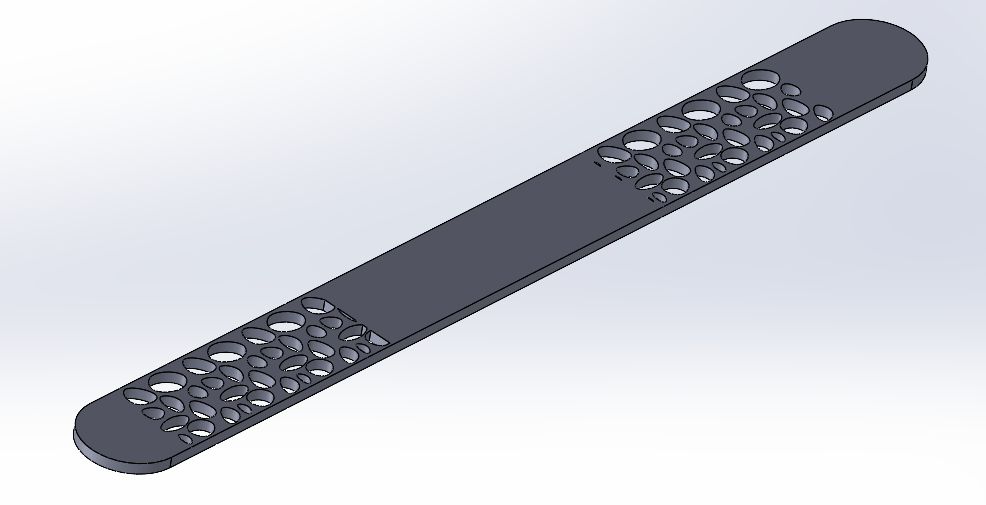
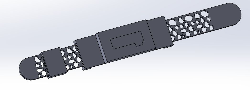
The wearable band was designed entirely in SolidWorks, using precise vernier caliper measurements of each physical component as the foundation for every dimension in the assembly. This approach allowed most pieces to fit correctly on the first print, with only the cover piece requiring iteration to dial in the tolerances around the electronics.
The main band features a Voronoi-inspired pattern across its surface, created by sketching a series of circles of varying sizes using the Spline tool in SolidWorks, then distributing them across the band surface using a linear pattern feature. The result is a lightweight, visually distinct structure that reduces material usage while preserving the flexibility that TPU provides — the open geometry also allows the filament to flex more naturally with wrist movement.
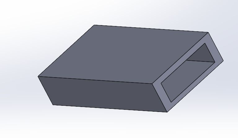
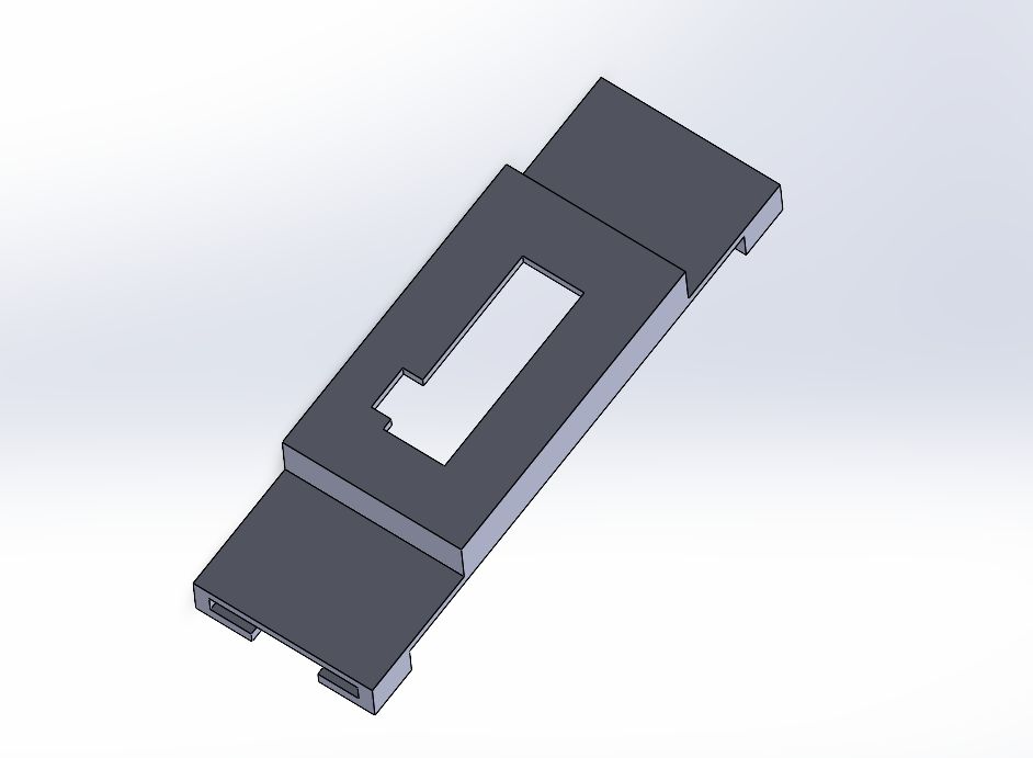
The central casing was designed as a two-level structure, with its internal dimensions taken directly from vernier measurements of the LiPo battery and the OLED module. The lower compartment seats the battery flush against the wrist, while the upper section provides a snug mount for the OLED display, keeping it level and stable during use. Getting these two levels to align correctly while maintaining a compact overall profile required careful planning of the wall thicknesses and internal clearances in SolidWorks before sending anything to print.
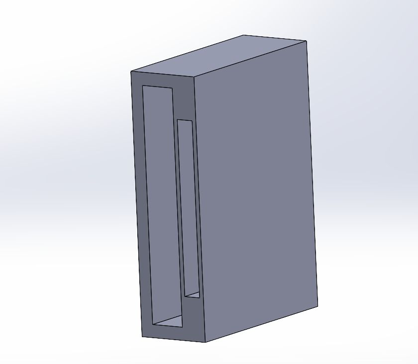
The sliding closure piece was designed around a dedicated channel built into the band body, with the internal slot dimensioned to accept a small neodymium magnet with minimal play. The sliding mechanism was kept intentionally simple — a single piece that locks into position — avoiding any moving parts that could fail or wear over time with the flexibility of the TPU.
The cover piece was the only component that required multiple print iterations. Because it needed to sit flush over the PCB and wiring while still being removable, the clearance tolerances were tighter than the rest of the assembly. Each iteration involved measuring the gap between the printed cover and the electronics with the vernier, adjusting the model in SolidWorks, and reprinting until the fit was clean and secure without requiring excessive force to install or remove.
With all individual parts combined and validated, the complete wearable assembly came together as a cohesive unit — each piece fitting into the next with the precision that the initial measurement process was intended to guarantee.
Electronics
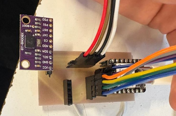
Before committing to a final PCB design, a series of breadboard prototype boards were assembled to test all the components together running the full firmware. While these boards were far from wearable, they served a critical purpose: validating that every sensor, the motor driver, the OLED display, and the pulse sensor could all communicate and function simultaneously on the same I2C bus without conflicts. This stage saved significant time by catching hardware and software issues early, long before any permanent soldering was involved.
The firmware running on these test boards handles multiple tasks concurrently — reading acceleration data from both the LSM6DS3 and BNO08x IMUs to calculate jerk in real time, monitoring heart rate through the MAX30102, driving the haptic motor when abnormal motion is detected, and updating the OLED display every 100ms with the current status. The following is the complete code used during this testing phase:
/*
 * WEARABLE - MOTION QUALITY
 * Hardware: XIAO nRF52840 Sense
 * Sensors: LSM6DS3 (interno), BNO08x, MAX30102, OLED 128x32
 *
 * I2C: SDA=D4, SCL=D5
 * Motor DC: D1
 */

#include <Wire.h>
#include <Adafruit_GFX.h>
#include <Adafruit_SSD1306.h>
#include <LSM6DS3.h>
#include <Adafruit_BNO08x.h>
#include "MAX30105.h"
#include "heartRate.h"

#define PIN_MOTOR      1
#define OLED_RESET    -1
#define SCREEN_WIDTH  128
#define SCREEN_HEIGHT  32

#define JERK_THRESHOLD      500.0f
#define JERK_CONFIRM_COUNT  3
#define MOTOR_ON_DURATION   800
#define JERK_ALERT_DURATION 2000
#define IR_MIN_SIGNAL       50000

Adafruit_SSD1306 oled(SCREEN_WIDTH, SCREEN_HEIGHT, &Wire, OLED_RESET);
LSM6DS3          imu(I2C_MODE, 0x6A);
Adafruit_BNO08x  bno;
MAX30105         particleSensor;

struct Vec3 { float x, y, z; };
Vec3  prevIMU        = {0, 0, 0};
Vec3  prevBNO        = {0, 0, 0};
unsigned long lastMotionTime = 0;
unsigned long jerkAlertTime  = 0;
bool  jerkDetected   = false;
uint8_t jerkCount    = 0;
unsigned long lastSampleTime = 0;
const uint16_t SAMPLE_INTERVAL_MS = 20;

const byte RATE_SIZE = 4;
byte  rates[RATE_SIZE];
byte  rateSpot       = 0;
long  lastBeat       = 0;
float beatsPerMinute = 0;
int   beatAvg        = 0;
byte  validReadings  = 0;

void setup() {
  Serial.begin(115200);
  delay(1000);
  Wire.begin();
  Wire.setClock(100000);
  delay(500);

  pinMode(PIN_MOTOR, OUTPUT);
  analogWrite(PIN_MOTOR, 0);

  oled.begin(SSD1306_SWITCHCAPVCC, 0x3C);
  oled.clearDisplay();
  oled.setTextColor(SSD1306_WHITE);
  oled.setTextSize(1);
  oled.setCursor(20, 4);  oled.print("WEARABLE MOTION");
  oled.setCursor(38, 18); oled.print("Loading...");
  oled.display();
  delay(1500);

  imu.begin();
  bno.begin_I2C(0x4B);
  bno.enableReport(SH2_LINEAR_ACCELERATION, 20000);
  particleSensor.begin(Wire, I2C_SPEED_STANDARD);
  particleSensor.setup(0x1F, 4, 2, 100, 411, 4096);

  lastSampleTime = millis();
}

void loop() {
  unsigned long now = millis();

  if (now - lastSampleTime >= SAMPLE_INTERVAL_MS) {
    float dt = (now - lastSampleTime) / 1000.0f;
    lastSampleTime = now;

    Vec3 accelIMU = {
      imu.readFloatAccelX(),
      imu.readFloatAccelY(),
      imu.readFloatAccelZ()
    };

    Vec3 accelBNO = {0, 0, 0};
    for (int i = 0; i < 10; i++) {
      sh2_SensorValue_t sv;
      if (bno.getSensorEvent(&sv)) {
        if (sv.sensorId == SH2_LINEAR_ACCELERATION) {
          accelBNO = {
            sv.un.linearAcceleration.x,
            sv.un.linearAcceleration.y,
            sv.un.linearAcceleration.z
          };
          break;
        }
      }
    }

    float dax = (accelIMU.x - prevIMU.x) / dt;
    float day = (accelIMU.y - prevIMU.y) / dt;
    float daz = (accelIMU.z - prevIMU.z) / dt;
    float jerkIMU = sqrt(dax*dax + day*day + daz*daz);

    float dbx = (accelBNO.x - prevBNO.x) / dt;
    float dby = (accelBNO.y - prevBNO.y) / dt;
    float dbz = (accelBNO.z - prevBNO.z) / dt;
    float jerkBNO = sqrt(dbx*dbx + dby*dby + dbz*dbz);

    prevIMU = accelIMU;
    prevBNO = accelBNO;

    float jerkFinal = max(jerkIMU, jerkBNO);

    if (jerkFinal > JERK_THRESHOLD) {
      jerkCount++;
      if (jerkCount >= JERK_CONFIRM_COUNT) {
        jerkDetected   = true;
        jerkAlertTime  = now;
        lastMotionTime = now;
      }
    } else {
      jerkCount = 0;
    }

    if (jerkDetected && (now - jerkAlertTime > JERK_ALERT_DURATION)) {
      jerkDetected = false;
    }
  }

  if (jerkDetected || (millis() - lastMotionTime < MOTOR_ON_DURATION)) {
    analogWrite(PIN_MOTOR, 140);
  } else {
    analogWrite(PIN_MOTOR, 0);
  }

  long irValue = particleSensor.getIR();

  if (irValue > IR_MIN_SIGNAL) {
    if (checkForBeat(irValue)) {
      long delta = millis() - lastBeat;
      lastBeat = millis();
      beatsPerMinute = 60.0f / (delta / 1000.0f);
      if (beatsPerMinute >= 50 && beatsPerMinute <= 180) {
        rates[rateSpot++ % RATE_SIZE] = (byte)beatsPerMinute;
        int sum = 0;
        for (byte x = 0; x < RATE_SIZE; x++) sum += rates[x];
        if (validReadings < RATE_SIZE) {
          validReadings++;
          beatAvg = (int)beatsPerMinute;
        } else {
          beatAvg = sum / RATE_SIZE;
        }
      }
    }
  } else {
    beatAvg = 0;
    beatsPerMinute = 0;
    rateSpot = 0;
    validReadings = 0;
    for (byte x = 0; x < RATE_SIZE; x++) rates[x] = 0;
  }

  static unsigned long lastOled = 0;
  if (millis() - lastOled >= 100) {
    lastOled = millis();
    oled.clearDisplay();

    if (jerkDetected) {
      oled.drawRect(0, 0, SCREEN_WIDTH, SCREEN_HEIGHT, SSD1306_WHITE);
      oled.setTextSize(1);
      int16_t x, y; uint16_t w, h;
      oled.getTextBounds("ABNORMAL MOTION", 0, 0, &x, &y, &w, &h);
      oled.setCursor((SCREEN_WIDTH - w) / 2, 4);
      oled.print("ABNORMAL MOTION");
      oled.setTextSize(2);
      oled.getTextBounds("ALERT!", 0, 0, &x, &y, &w, &h);
      oled.setCursor((SCREEN_WIDTH - w) / 2, 16);
      oled.print("ALERT!");
    } else {
      int16_t x, y; uint16_t w, h;
      if (irValue < IR_MIN_SIGNAL || beatAvg == 0) {
        oled.setTextSize(1);
        oled.getTextBounds("NO SIGNAL", 0, 0, &x, &y, &w, &h);
        oled.setCursor((SCREEN_WIDTH - w) / 2, 4);
        oled.print("NO SIGNAL");
        oled.setTextSize(2);
        oled.getTextBounds("------", 0, 0, &x, &y, &w, &h);
        oled.setCursor((SCREEN_WIDTH - w) / 2, 16);
        oled.print("------");
      } else {
        oled.setTextSize(1);
        oled.getTextBounds("HEART RATE", 0, 0, &x, &y, &w, &h);
        oled.setCursor((SCREEN_WIDTH - w) / 2, 2);
        oled.print("HEART RATE");
        char bpmStr[8];
        sprintf(bpmStr, "%d BPM", beatAvg);
        oled.setTextSize(2);
        oled.getTextBounds(bpmStr, 0, 0, &x, &y, &w, &h);
        oled.setCursor((SCREEN_WIDTH - w) / 2, 14);
        oled.print(bpmStr);
      }
    }

    oled.display();
  }

  delay(5);
}
With the firmware validated on breadboard, the next step was fabricating a more permanent circuit. Following the same vinyl cutting method used in week 3, the traces were cut in flexible copper tape — a process that works well for flat, rigid connections but would ultimately reveal its limitations in this context.
To generate the cutting file from KiCad, the process was straightforward:
1. Export from KiCad: Go to File → Plot.
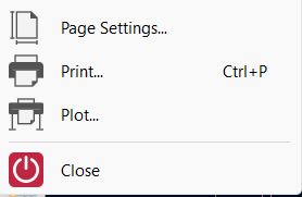
2. Export parameters: Select the F.Cu layer and export it as an SVG file.
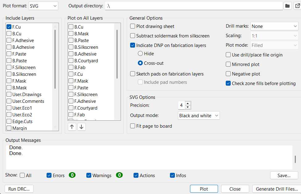
3. Import into Inkscape and follow week 3 process: Open the exported SVG in Inkscape to prepare it for the vinyl cutter and from this point, follow the same steps outlined in week 3 to prepare and cut the copper traces.
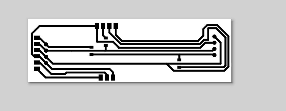
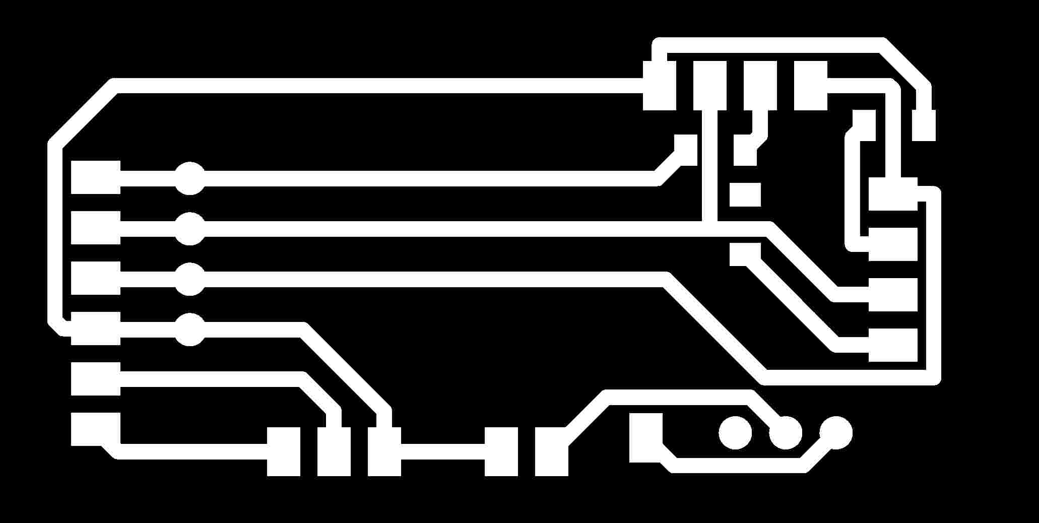
Once the paths were cut and weeded, the traces were transferred onto the final substrate using the paper transfer method, resulting in the copper layout shown below.
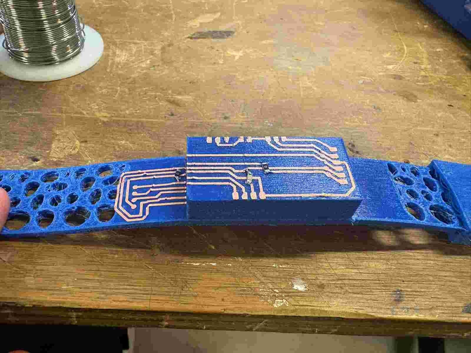
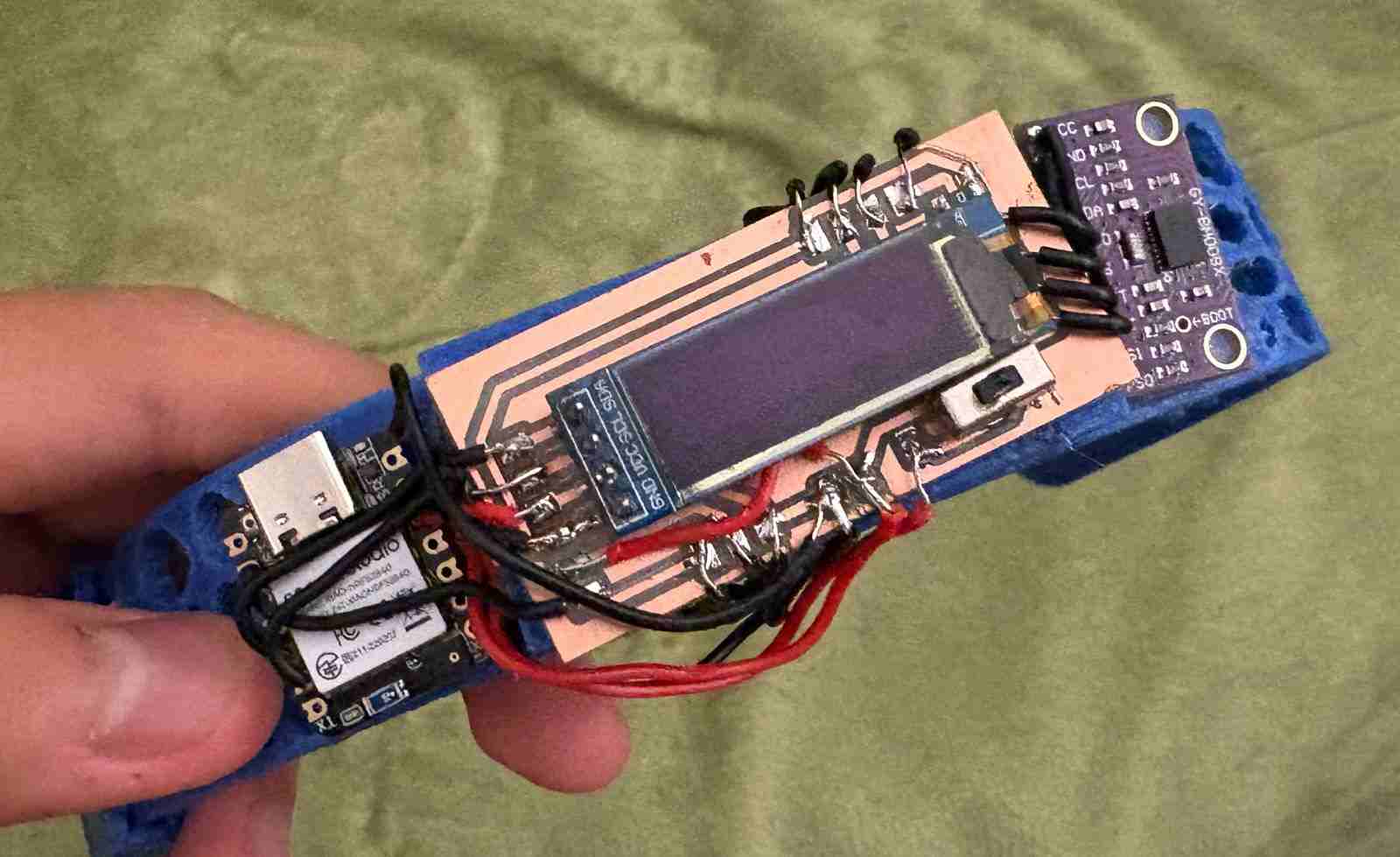
Soldering the components onto the flexible copper tape proved to be far more challenging than anticipated. Because several components needed to be bent or repositioned to fit the wearable form factor, the copper traces would lift, shift, or crack under the stress. No matter how carefully each joint was approached, at least one component would lose its connection during the assembly process. The method works exceptionally well for flat, rigid, or direct connections — and in that context it performed perfectly — but the requirement to physically bend components around the band geometry made it fundamentally incompatible with this application. The result, unfortunately, was an unusable board.
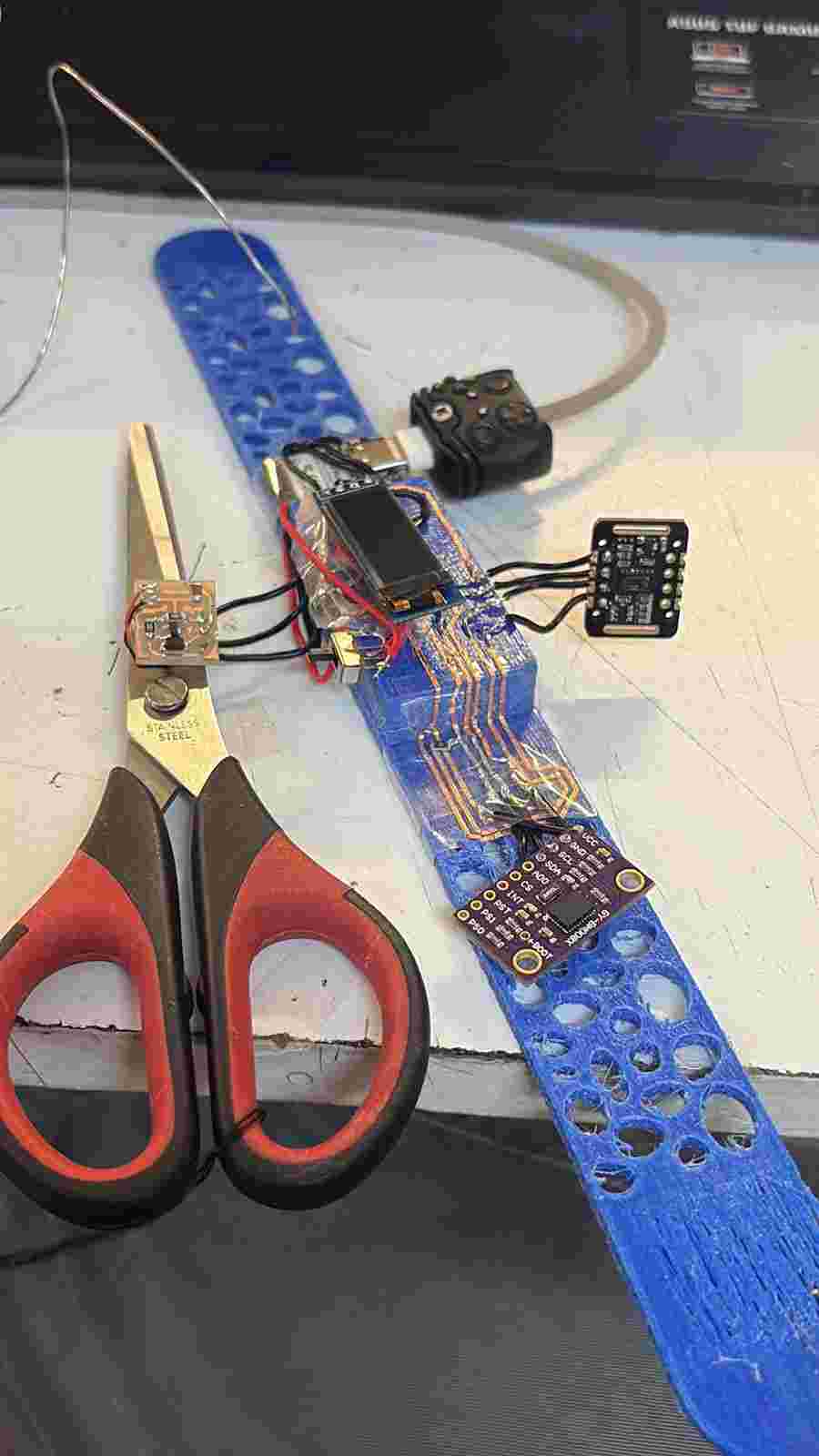
A silver lining emerged from the copper tape process: while working out the dimensions and component placement for the flexible version, the exact measurements for a rigid PCB were essentially figured out as a byproduct. Rather than starting the layout from scratch, those dimensions were carried directly into a traditional rigid board design, which was then fabricated and proved to be a much more reliable foundation for soldering all the components cleanly and securely.
With the rigid board in place, all components were soldered successfully and the full system came together as a functional unit for the first time outside of a breadboard setup.
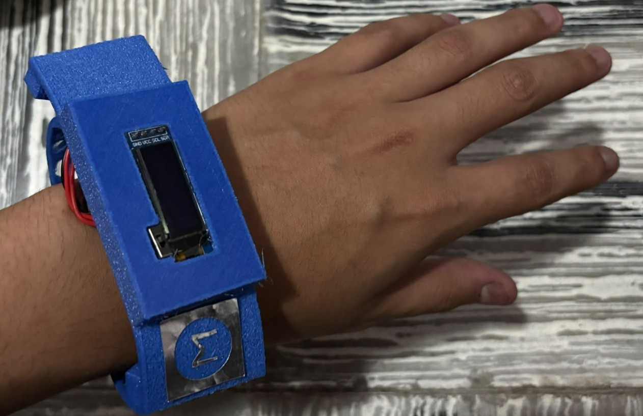
Finally, with the 3D printed cover installed over the electronics, the wearable begins to take on its intended form — closer to a finished product than a prototype, with the components neatly encapsulated beneath the TPU shell.
Edge Impulse — Machine Learning Model
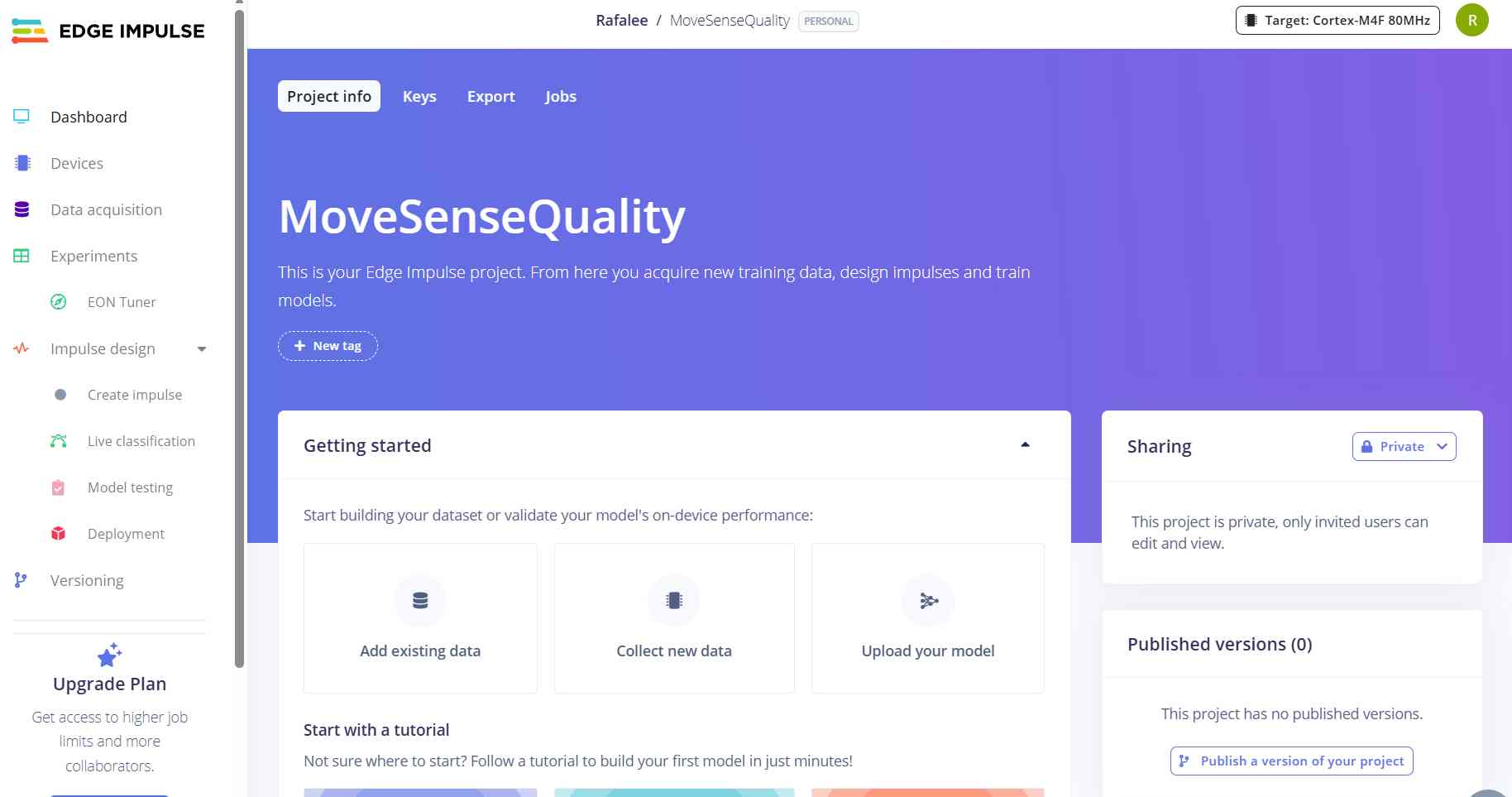
Edge Impulse is a platform designed for training and deploying machine learning models directly onto embedded devices and microcontrollers. For this project, the goal was to use it to train a classification model capable of distinguishing between normal movement and different types of abnormal motion — using real sensor data captured directly from the wearable — so that instead of relying solely on a manually tuned jerk threshold, the device could make more intelligent, data-driven decisions about what constitutes an irregular movement pattern.
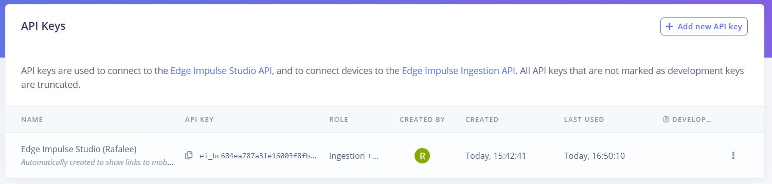
The first step was creating a new project on the platform and navigating to the Keys section to retrieve the API key, which would be needed to connect the data collection script to the project.
With the API key in hand, a custom Python data forwarder script was written to capture live sensor readings from the XIAO over serial and upload them directly to Edge Impulse. The script reads accelerometer data from both IMUs at 50Hz, asks for a label and duration at runtime, collects the specified number of samples, and then sends the full dataset to the Edge Impulse ingestion API with the appropriate headers and metadata.
import serial
import requests
import json
import time

API_KEY = "ei_bc684ea787a31e16003f8fb867ef3172dd55cb056a54f6b0"
COM_PORT = "COM18"
BAUD_RATE = 115200
FREQUENCY = 50  # Hz

ser = serial.Serial(COM_PORT, BAUD_RATE, timeout=1)
time.sleep(2)

print("Conectado a", COM_PORT)
print("Enviando datos a Edge Impulse...")
print("Presiona Ctrl+C para detener")

samples = []
label = input("Nombre de la etiqueta (ej: normal, brusco): ")
duration = int(input("Duracion en segundos: "))
total_samples = duration * FREQUENCY

print(f"Grabando {total_samples} muestras para '{label}'...")
time.sleep(1)

while len(samples) < total_samples:
    line = ser.readline().decode('utf-8').strip()
    if line:
        try:
            values = [float(x) for x in line.split(',')]
            if len(values) == 6:
                samples.append(values)
                print(f"Muestras: {len(samples)}/{total_samples}", end='\r')
        except:
            pass

print(f"\nGrabacion completa. Subiendo a Edge Impulse...")

payload = {
    "protected": {
        "ver": "v1",
        "alg": "none",
        "iat": int(time.time())
    },
    "signature": "0000",
    "payload": {
        "device_name": "xiao-nrf52840",
        "device_type": "XIAO_NRF52840",
        "interval_ms": 1000 / FREQUENCY,
        "sensors": [
            {"name": "imu_ax", "units": "m/s2"},
            {"name": "imu_ay", "units": "m/s2"},
            {"name": "imu_az", "units": "m/s2"},
            {"name": "bno_ax", "units": "m/s2"},
            {"name": "bno_ay", "units": "m/s2"},
            {"name": "bno_az", "units": "m/s2"}
        ],
        "values": samples
    }
}

headers = {
    "x-api-key": API_KEY,
    "Content-Type": "application/json",
    "x-file-name": f"{label}.json",
    "x-label": label
}

response = requests.post(
    "https://ingestion.edgeimpulse.com/api/training/data",
    headers=headers,
    data=json.dumps(payload)
)

if response.status_code == 200:
    print("Datos subidos exitosamente!")
    print(response.json())
else:
    print(f"Error: {response.status_code}")
    print(response.text)

ser.close()
Before running the script, the required Python libraries need to be installed. Open a terminal and run:
pip install pyserial requestsOnce installed, the script is run from the terminal with:
python forwarder.pyWhen the script runs, it prompts for a movement label and a recording duration in seconds. Once confirmed, it begins capturing sensor data while the user performs the specified type of movement. For this project, data was collected across five movement categories — normal, sharp jerk, tremor, spasm, and impact — recording 5 sessions per category at 30 seconds each for normal movement and 10 seconds each for the abnormal categories, resulting in a total dataset of approximately 7 minutes and 25 seconds of labeled motion data. The following shows a successful data upload session.
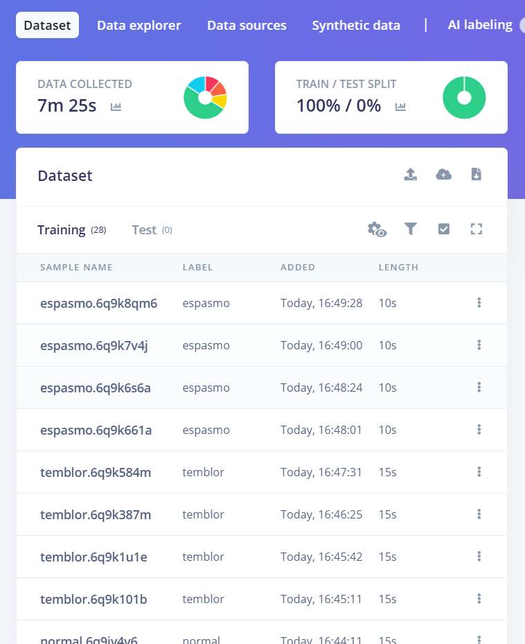
Below are two example recording sessions — one capturing normal everyday wrist movement, and one capturing a sharp, abrupt motion — to illustrate what the data collection process looked like in practice.
Using this process, data was collected across five movement categories: normal, sharp jerk, tremor, spasm, and impact. Each category was recorded across multiple sessions of varying duration to give the model enough examples to learn the distinguishing characteristics of each movement type.
With the dataset collected, the model was built and trained through the following steps in Edge Impulse:
1. Create Impulse and add processing block: Navigate to Impulse Design, click Create Impulse, and add a processing block to define how the raw sensor data will be transformed before training.
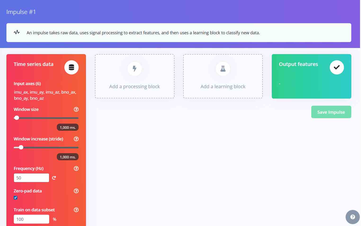
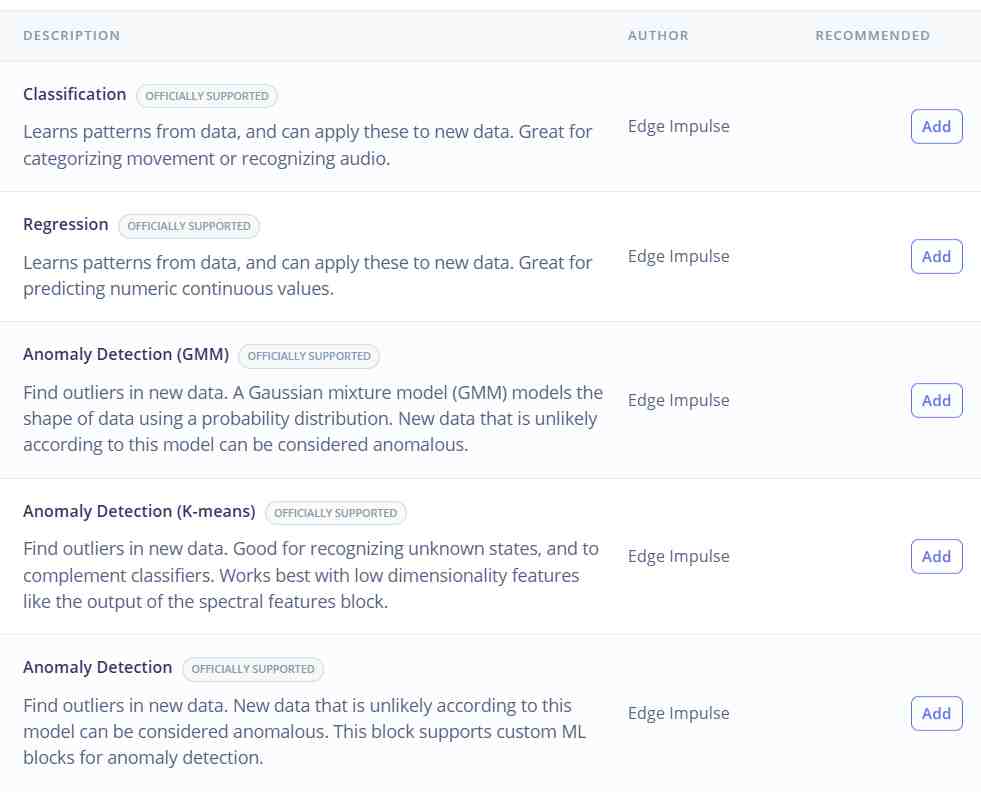
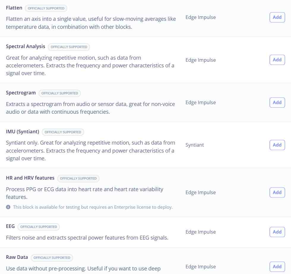
2. Choose the Classifier block: From the available learning blocks, select Classification — the appropriate choice when the goal is to categorize input data into distinct labeled categories.
3. Add a learning block: With the classifier selected, add it to the impulse to define the model architecture that will learn from the processed features.
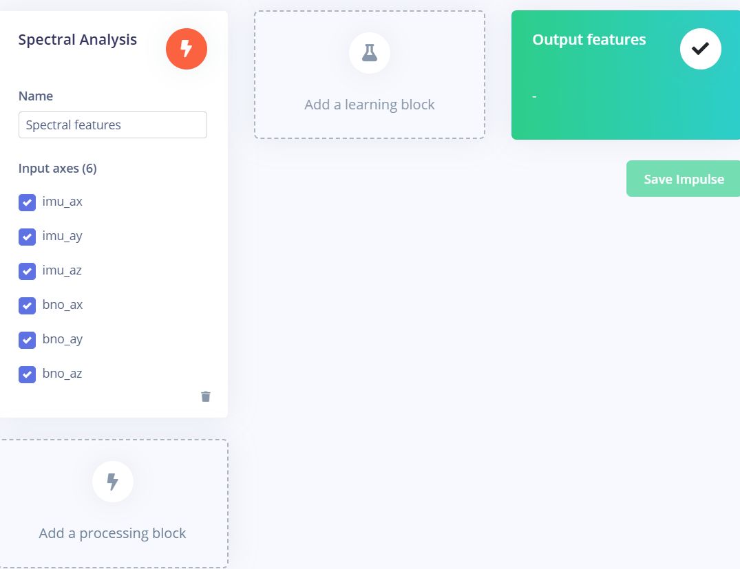
4. Choose Spectral Analysis: Select Spectral Analysis as the processing block — this method extracts frequency-domain features from the time-series accelerometer data, which is well suited for distinguishing between different motion patterns.
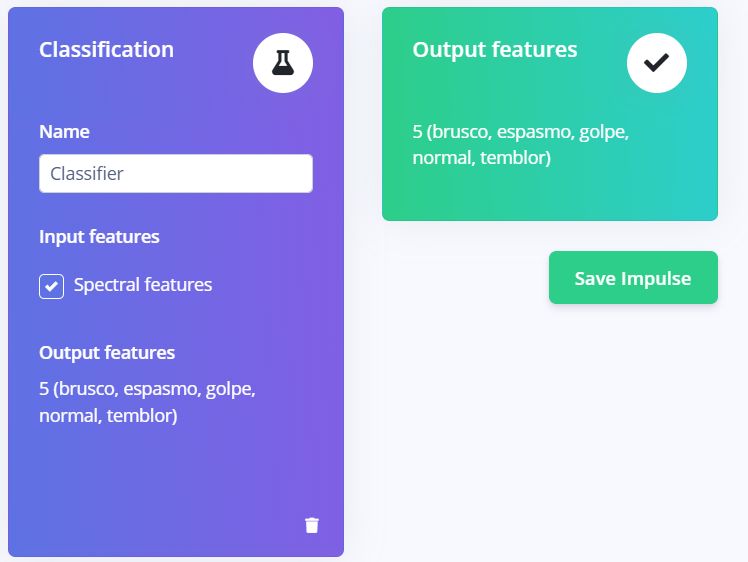
5. Review classes and save impulse: The platform automatically detects all labeled categories present in the dataset. Once confirmed, save the impulse to lock in the configuration.
6. Generate parameters in Spectral Features: Navigate to the Spectral Features section and use the Autotune Parameters option to automatically determine the optimal DSP settings for the dataset.
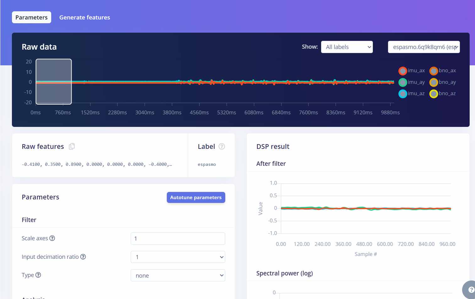
7. Generate features: Run the feature generation process, which processes all training samples through the spectral analysis block and prepares them for model training.
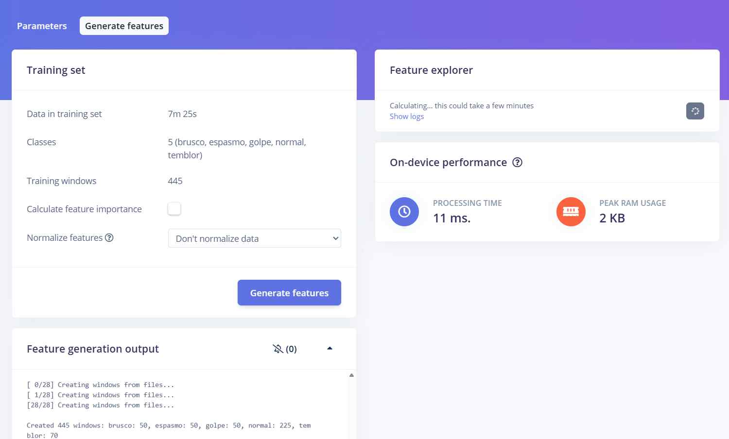
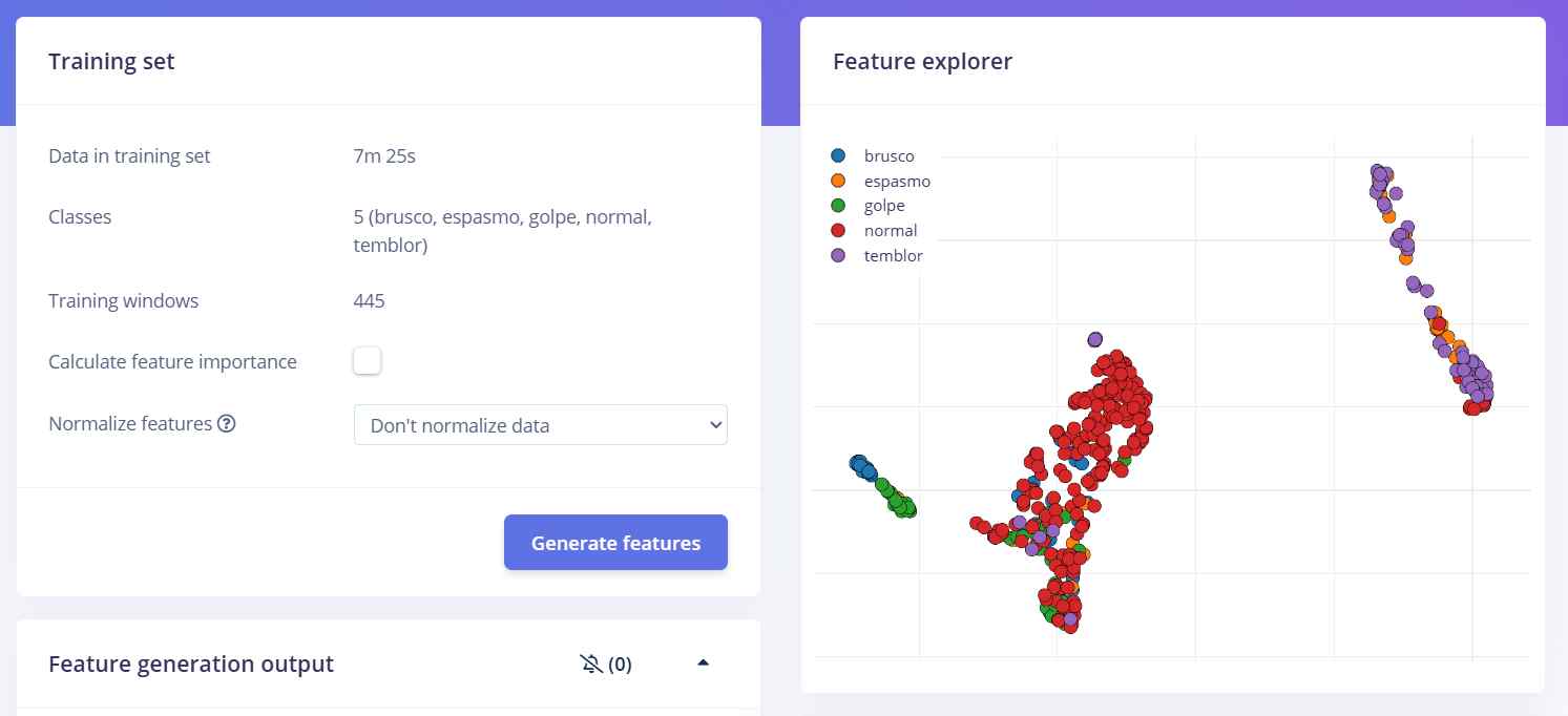
8. Review the feature explorer: Once generation is complete, the Feature Explorer visualizes how well-separated the different movement classes are in the feature space — an early indicator of how well the model will perform.
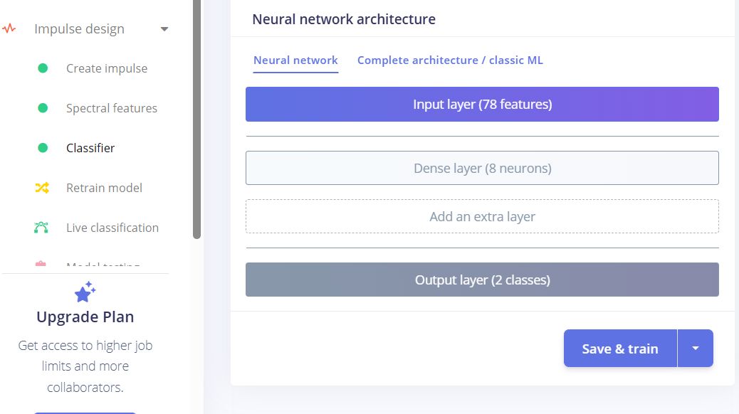
9. Train the model: Navigate to Classifier and click Save and Train. The platform trains a neural network on the generated features and reports accuracy and loss metrics upon completion.
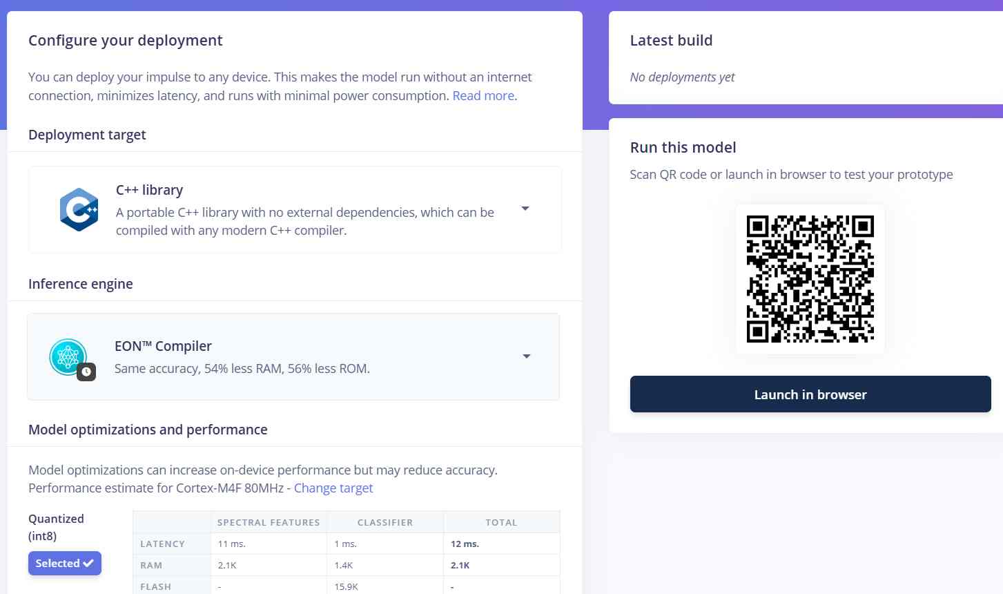
10. Deploy and export: Go to Deployment, click Build, and the platform generates a .zip file containing the trained model as a C++ library, ready to be added directly to the Arduino IDE libraries folder.
The resulting model demonstrated solid classification performance during training, successfully distinguishing between the five movement categories with meaningful accuracy. However, when attempting to deploy it onto the XIAO nRF52840, the device ran out of available RAM before the classifier could execute — the combined memory footprint of the model, the sensor libraries, and the OLED driver exceeded what the microcontroller could accommodate at runtime. Despite this hardware limitation, the trained model stands as a valid representation of what a more capable deployment target would be able to run, and the methodology — data collection, spectral feature extraction, and neural network classification — remains fully applicable to this use case with a device that offers more memory headroom.
Final Implementation
Due to the RAM limitations of the XIAO nRF52840 previously mentioned, running a full Edge Impulse inference model directly on the microcontroller was not feasible within the scope of this project. However, the trained model was not without purpose — by analyzing the labeled movement data collected across both normal and abnormal categories, the model's learned feature boundaries were used to statistically derive the jerk threshold that best separates the two classes. This process yielded the confirmed 500 m/s³ threshold with 3 consecutive confirmations, which is a direct product of the machine learning pipeline rather than a manually guessed value. As a result, the final firmware implementation focuses on real-time jerk calculation using sensor fusion between the LSM6DS3 and BNO08x, applying this data-driven threshold for anomaly detection. This data is then transmitted over BLE to the PWA, where the anomaly score is computed and displayed. The architecture remains fully compatible with a future Edge Impulse integration once the hardware constraints are addressed.
Final Firmware — movesense.ino
The following is the complete final firmware loaded onto the XIAO nRF52840 Sense. It handles sensor fusion jerk detection, heart rate monitoring, haptic feedback via the DC motor, OLED display output, and BLE broadcasting of a 24-byte packet containing all relevant movement and physiological data.
/*
 * WEARABLE - MOTION QUALITY
 * Hardware: XIAO nRF52840 Sense
 * Sensors: LSM6DS3 (interno), BNO08x, MAX30102, OLED 128x32
 *
 * I2C: SDA=D4, SCL=D5
 * Motor DC: D1
 *
 * BLE: transmits [jerkFinal, ax, ay, az, beatAvg, battery%] as 6 x Float32 (24 bytes)
 * every 20ms via GATT notification.
 */

#include <Wire.h>
#include <Adafruit_GFX.h>
#include <Adafruit_SSD1306.h>
#include <LSM6DS3.h>
#include <Adafruit_BNO08x.h>
#include "MAX30105.h"
#include "heartRate.h"
#include <ArduinoBLE.h>

// ── Pins ───────────────────────────────────────────────────────
#define PIN_MOTOR      1
#define OLED_RESET    -1
#define SCREEN_WIDTH  128
#define SCREEN_HEIGHT  32
#define PIN_VBAT       A0
#define VBAT_ENABLE    14

// ── Thresholds ─────────────────────────────────────────────────
#define JERK_THRESHOLD      500.0f
#define JERK_CONFIRM_COUNT  3
#define MOTOR_ON_DURATION   800
#define JERK_ALERT_DURATION 2000
#define IR_MIN_SIGNAL       50000

// ── BLE UUIDs ──────────────────────────────────────────────────
#define SERVICE_UUID  "12345678-1234-1234-1234-123456789abc"
#define CHAR_UUID     "12345678-1234-1234-1234-123456789abd"

// ── BLE instances ──────────────────────────────────────────────
BLEService        motionService(SERVICE_UUID);
BLECharacteristic motionChar(CHAR_UUID, BLENotify, 24);

// ── Sensor instances ───────────────────────────────────────────
Adafruit_SSD1306 oled(SCREEN_WIDTH, SCREEN_HEIGHT, &Wire, OLED_RESET);
LSM6DS3          imu(I2C_MODE, 0x6A);
Adafruit_BNO08x  bno;
MAX30105         particleSensor;

// ── Jerk variables ─────────────────────────────────────────────
struct Vec3 { float x, y, z; };
Vec3  prevIMU        = {0, 0, 0};
Vec3  prevBNO        = {0, 0, 0};
unsigned long lastMotionTime = 0;
unsigned long jerkAlertTime  = 0;
bool  jerkDetected   = false;
uint8_t jerkCount    = 0;
unsigned long lastSampleTime = 0;
const uint16_t SAMPLE_INTERVAL_MS = 20;

// ── MAX30102 variables ─────────────────────────────────────────
const byte RATE_SIZE = 4;
byte  rates[RATE_SIZE];
byte  rateSpot       = 0;
long  lastBeat       = 0;
float beatsPerMinute = 0;
int   beatAvg        = 0;
byte  validReadings  = 0;

// ── Battery ────────────────────────────────────────────────────
float readBattery() {
  digitalWrite(VBAT_ENABLE, LOW);
  delay(1);
  int raw = analogRead(PIN_VBAT);
  float voltage = raw * (3.3f / 1023.0f) * 2.0f;
  float pct = ((voltage - 3.5f) / (4.2f - 3.5f)) * 100.0f;
  return constrain(pct, 0.0f, 100.0f);
}

// ── BLE helper ─────────────────────────────────────────────────
void bleSend(float jerk, float ax, float ay, float az, float hr, float batt) {
  if (!BLE.connected()) return;
  uint8_t buf[24];
  float vals[6] = { jerk, ax, ay, az, hr, batt };
  memcpy(buf, vals, 24);
  motionChar.writeValue(buf, 24);
}

// ══════════════════════════════════════════════════════════════
void setup() {
  Serial.begin(115200);
  delay(1000);

  Wire.begin();
  Wire.setClock(100000);
  delay(500);

  pinMode(PIN_MOTOR, OUTPUT);
  analogWrite(PIN_MOTOR, 0);

  pinMode(PIN_VBAT, INPUT);
  pinMode(VBAT_ENABLE, OUTPUT);
  digitalWrite(VBAT_ENABLE, LOW);

  // ── OLED ──
  oled.begin(SSD1306_SWITCHCAPVCC, 0x3C);
  oled.clearDisplay();
  oled.setTextColor(SSD1306_WHITE);
  oled.setTextSize(1);
  oled.setCursor(20, 4);  oled.print("WEARABLE MOTION");
  oled.setCursor(38, 18); oled.print("Loading...");
  oled.display();
  delay(1500);

  // ── LSM6DS3 ──
  imu.begin();
  Serial.println("IMU OK");

  // ── BNO08x ──
  bno.begin_I2C(0x4B);
  bno.enableReport(SH2_LINEAR_ACCELERATION, 20000);
  Serial.println("BNO OK");

  // ── MAX30102 ──
  particleSensor.begin(Wire, I2C_SPEED_STANDARD);
  particleSensor.setup(0x1F, 4, 2, 100, 411, 4096);
  Serial.println("MAX OK");

  // ── BLE ──
  BLE.begin();
  BLE.setLocalName("MoveSense XIAO");
  BLE.setDeviceName("MoveSense XIAO");
  BLE.setAdvertisedService(motionService);
  motionService.addCharacteristic(motionChar);
  BLE.addService(motionService);
  BLE.advertise();
  Serial.println("BLE advertising as 'MoveSense XIAO'");

  lastSampleTime = millis();
  Serial.println("System ready.");
}

// ══════════════════════════════════════════════════════════════
void loop() {
  BLE.poll();

  unsigned long now = millis();

  // ── 1. Jerk ──────────────────────────────────────────────────
  float jerkFinal  = 0;
  float accelIMU_x = 0, accelIMU_y = 0, accelIMU_z = 0;

  if (now - lastSampleTime >= SAMPLE_INTERVAL_MS) {
    float dt = (now - lastSampleTime) / 1000.0f;
    lastSampleTime = now;

    Vec3 accelIMU = {
      imu.readFloatAccelX(),
      imu.readFloatAccelY(),
      imu.readFloatAccelZ()
    };

    Vec3 accelBNO = {0, 0, 0};
    for (int i = 0; i < 10; i++) {
      sh2_SensorValue_t sv;
      if (bno.getSensorEvent(&sv)) {
        if (sv.sensorId == SH2_LINEAR_ACCELERATION) {
          accelBNO = {
            sv.un.linearAcceleration.x,
            sv.un.linearAcceleration.y,
            sv.un.linearAcceleration.z
          };
          break;
        }
      }
    }

    float dax = (accelIMU.x - prevIMU.x) / dt;
    float day = (accelIMU.y - prevIMU.y) / dt;
    float daz = (accelIMU.z - prevIMU.z) / dt;
    float jerkIMU = sqrt(dax*dax + day*day + daz*daz);

    float dbx = (accelBNO.x - prevBNO.x) / dt;
    float dby = (accelBNO.y - prevBNO.y) / dt;
    float dbz = (accelBNO.z - prevBNO.z) / dt;
    float jerkBNO = sqrt(dbx*dbx + dby*dby + dbz*dbz);

    prevIMU = accelIMU;
    prevBNO = accelBNO;

    jerkFinal  = max(jerkIMU, jerkBNO);
    accelIMU_x = accelIMU.x;
    accelIMU_y = accelIMU.y;
    accelIMU_z = accelIMU.z;

    if (jerkFinal > JERK_THRESHOLD) {
      jerkCount++;
      if (jerkCount >= JERK_CONFIRM_COUNT) {
        jerkDetected   = true;
        jerkAlertTime  = now;
        lastMotionTime = now;
        Serial.print("JERK: "); Serial.println(jerkFinal);
      }
    } else {
      jerkCount = 0;
    }

    if (jerkDetected && (now - jerkAlertTime > JERK_ALERT_DURATION)) {
      jerkDetected = false;
    }

    float batt = readBattery();
    bleSend(jerkFinal, accelIMU_x, accelIMU_y, accelIMU_z, (float)beatAvg, batt);
  }

  // ── 2. Motor ─────────────────────────────────────────────────
  if (jerkDetected || (millis() - lastMotionTime < MOTOR_ON_DURATION)) {
    analogWrite(PIN_MOTOR, 140);
  } else {
    analogWrite(PIN_MOTOR, 0);
  }

  // ── 3. Heart Rate ────────────────────────────────────────────
  long irValue = particleSensor.getIR();
  if (irValue > IR_MIN_SIGNAL) {
    if (checkForBeat(irValue)) {
      long delta = millis() - lastBeat;
      lastBeat = millis();
      beatsPerMinute = 60.0f / (delta / 1000.0f);
      if (beatsPerMinute >= 50 && beatsPerMinute <= 180) {
        rates[rateSpot++ % RATE_SIZE] = (byte)beatsPerMinute;
        int sum = 0;
        for (byte x = 0; x < RATE_SIZE; x++) sum += rates[x];
        if (validReadings < RATE_SIZE) {
          validReadings++;
          beatAvg = (int)beatsPerMinute;
        } else {
          beatAvg = sum / RATE_SIZE;
        }
      }
    }
  } else {
    beatAvg        = 0;
    beatsPerMinute = 0;
    rateSpot       = 0;
    validReadings  = 0;
    for (byte x = 0; x < RATE_SIZE; x++) rates[x] = 0;
  }

  // ── 4. OLED ──────────────────────────────────────────────────
  static unsigned long lastOled = 0;
  if (millis() - lastOled >= 100) {
    lastOled = millis();
    oled.clearDisplay();

    if (jerkDetected) {
      oled.drawRect(0, 0, SCREEN_WIDTH, SCREEN_HEIGHT, SSD1306_WHITE);
      oled.setTextSize(1);
      int16_t x, y; uint16_t w, h;
      oled.getTextBounds("ABNORMAL MOTION", 0, 0, &x, &y, &w, &h);
      oled.setCursor((SCREEN_WIDTH - w) / 2, 4);
      oled.print("ABNORMAL MOTION");
      oled.setTextSize(2);
      oled.getTextBounds("ALERT!", 0, 0, &x, &y, &w, &h);
      oled.setCursor((SCREEN_WIDTH - w) / 2, 16);
      oled.print("ALERT!");
    } else {
      int16_t x, y; uint16_t w, h;
      if (irValue < IR_MIN_SIGNAL || beatAvg == 0) {
        oled.setTextSize(1);
        oled.getTextBounds("NO SIGNAL", 0, 0, &x, &y, &w, &h);
        oled.setCursor((SCREEN_WIDTH - w) / 2, 4);
        oled.print("NO SIGNAL");
        oled.setTextSize(2);
        oled.getTextBounds("------", 0, 0, &x, &y, &w, &h);
        oled.setCursor((SCREEN_WIDTH - w) / 2, 16);
        oled.print("------");
      } else {
        oled.setTextSize(1);
        oled.getTextBounds("HEART RATE", 0, 0, &x, &y, &w, &h);
        oled.setCursor((SCREEN_WIDTH - w) / 2, 2);
        oled.print("HEART RATE");
        char bpmStr[8];
        sprintf(bpmStr, "%d BPM", beatAvg);
        oled.setTextSize(2);
        oled.getTextBounds(bpmStr, 0, 0, &x, &y, &w, &h);
        oled.setCursor((SCREEN_WIDTH - w) / 2, 14);
        oled.print(bpmStr);
      }
    }
    oled.display();
  }

  delay(5);
}
iOS Compatibility — Bluefy
Web Bluetooth is not supported on iOS in any browser, including Chrome and Safari, due to platform restrictions imposed by Apple. To connect the wearable to an iPhone, Bluefy — a third-party browser available on the App Store with native Web Bluetooth support — was used. Once installed and granted Bluetooth permissions, Bluefy loads the GitHub Pages URL and connects to the XIAO normally.
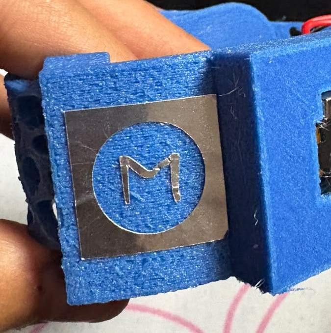
Vinyl Cut — MoveSense Sticker
Following the same vinyl cutting procedure documented in week 3, a sticker was cut using the MoveSense icon logo — adding a small branding detail to the final wearable assembly.

Final Result
The following video shows the complete system working end to end — the XIAO nRF52840 Sense running the final firmware, transmitting real sensor data over BLE, and the MoveSense PWA displaying live jerk values, heart rate, and anomaly score in real time. This represents the final functional state of the wearable and its companion interface as delivered for this project.
Files
└── ProyectoFinal
    ├── InterfaceFP
    │   │   index.html
    │   │   manifest.json
    │   │   movesense-final-index.html
    │   │   sw.js
    │   │
    │   └── icons
    │           icon-192.png
    │           icon-512.png
    │           icon-96.png
    │
    ├── Kicad
    │   ├── FinalProjectFlex
    │   │   │   FinalProject6-F_Cu.dxf
    │   │   │   FinalProject6-F_Cu.svg
    │   │   │   FinalProject6.kicad_pcb
    │   │   │   FinalProject6.kicad_prl
    │   │   │   FinalProject6.kicad_pro
    │   │   │   FinalProject6.kicad_sch
    │   │   │   fp-info-cache
    │   │   │
    │   │   └── FinalProject6-backups
    │   │           FinalProject6-2026-06-03_150229.zip
    │   │           FinalProject6-2026-06-03_152650.zip
    │   │           FinalProject6-2026-06-03_161634.zip
    │   │           FinalProject6-2026-06-03_162845.zip
    │   │           FinalProject6-2026-06-03_193316.zip
    │   │           FinalProject6-2026-06-04_164949.zip
    │   │           FinalProject6-2026-06-05_003003.zip
    │   │
    │   ├── FinalProjectPCB
    │   │   │   FinalProject7-Edge_Cuts.gbr
    │   │   │   FinalProject7-F_Cu.gbr
    │   │   │   FinalProject7-job.gbrjob
    │   │   │   FinalProject7-NPTH.drl
    │   │   │   FinalProject7-PTH.drl
    │   │   │   FinalProject7.kicad_pcb
    │   │   │   FinalProject7.kicad_pro
    │   │   │   FinalProject7.kicad_sch
    │   │   │
    │   │   ├── Cuts
    │   │   │       Cutout.rml
    │   │   │       Drills.rml
    │   │   │       Traces.rml
    │   │   │
    │   │   └── FinalProject7-backups
    │   │           FinalProject7-2026-06-05_004900.zip
    │   │           FinalProject7-2026-06-05_005904.zip
    │   │           FinalProject7-2026-06-05_012315.zip
    │   │
    │   └── MotorFinal
    │       │   Cuts.zip
    │       │   MotorFinal-B_Cu.gbr
    │       │   MotorFinal-B_Mask.gbr
    │       │   MotorFinal-B_Paste.gbr
    │       │   MotorFinal-B_Silkscreen.gbr
    │       │   MotorFinal-Edge_Cuts.gbr
    │       │   MotorFinal-F_Cu.gbr
    │       │   MotorFinal-F_Mask.gbr
    │       │   MotorFinal-F_Paste.gbr
    │       │   MotorFinal-F_Silkscreen.gbr
    │       │   MotorFinal-job.gbrjob
    │       │   MotorFinal-NPTH.drl
    │       │   MotorFinal-PTH.drl
    │       │   MotorFinal.kicad_pcb
    │       │   MotorFinal.kicad_prl
    │       │   MotorFinal.kicad_pro
    │       │   MotorFinal.kicad_sch
    │       │
    │       ├── Cuts
    │       │       MotorCutout.rml
    │       │       MotorDrills.rml
    │       │       MotorTraces.rml
    │       │
    │       └── MotorFinal-backups
    │               MotorFinal-2026-06-03_161444.zip
    │
    ├── Solid
    │       Banda.SLDPRT
    │       CarcasaSuperior.SLDPRT
    │       CarcasaSuperior.STL
    │       Deslizante.SLDPRT
    │       Deslizante.STL
    │       Tapa.SLDPRT
    │       Tapa.STL
    │       Wearable.SLDASM
    │       Wearable.STL
    │       WearableFinal.SLDASM
    │
    └── VinylCut
            Circuito.dxf
            Circuito.svg
            Sticker.png
            Sticker.svg