Embedded Programming - Assignment:
The objective of this week was to browse through the datasheet of a microcontroller and, based on that information, write and test a program for an embedded system using the microcontroller to interact with local input and/or output devices, as well as to communicate through remote wired or wireless connections.
Microcontroller - Xiao nrf52840 Sense
For my project, I decided to use the Xiao nrf52840 Sense from Seeed Studio mainly because it already includes a built-in gyroscope and accelerometer. This is very convenient for my application, since it allows me to measure motion and orientation directly without needing to add an external IMU module, such as an MPU sensor. By having these sensors integrated into the board, the design becomes more compact, the wiring is simpler, and the overall system is more reliable. It also reduces power consumption and development time, because I can work with the onboard components using the provided libraries instead of configuring additional hardware.
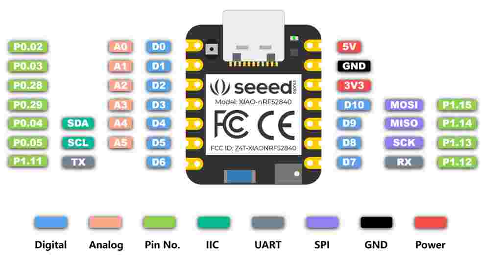
XIAO Pin-out
XIAO nRF52840 Key Features
The Seeed Studio XIAO nRF52840 series stands out for its high performance and ultra-low power consumption, making it ideal for wearable and wireless projects.
- Wireless Connectivity: Bluetooth 5.0 with a high-performance onboard antenna.
- Processing Power: Nordic nRF52840, ARM® Cortex®-M4 32-bit processor with FPU, running at 64 MHz.
- Ultra-Low Power: Designed for efficiency with standby power consumption under 5μA.
- Power Management: Integrated battery charging chip for lithium battery charge and discharge management.
- Memory: Onboard 2 MB flash for extended storage requirements.
- Advanced Sensors (Sense version): Includes an onboard PDM microphone and a 6-axis LSM6DS3TR-C IMU.
- Compact Form Factor: Ultra-small size (21 x 17.8mm), perfect for wearable devices.
- Rich Interfaces: Supports UART, I2C, SPI, NFC, SWD, and multiple GPIO/ADC pins depending on the specific model.
- SMD Design: Single-sided components and surface mounting design for easy integration.
XIAO nRF52840 Series Overview
The Seeed Studio XIAO nRF52840 is an ultra-compact microcontroller designed for wearables and IoT. Powered by the Nordic nRF52840 MCU, it integrates Bluetooth 5.0 and features a single-sided, surface-mountable design with an onboard antenna.
Standard & Sense
11 Digital I/O (PWM) and 6 Analog I/O (ADC). The Sense version adds a PDM Microphone for audio and a 6-axis IMU for TinyML and gesture recognition.
Plus Versions
Upgraded to 20 multifunctional pins, including I2S and extra SPI resources. Features exposed NFC pins and optimized BAT pin layout for easier soldering.
Hardware & Connectivity
- Interfaces: Supports NFC, UART, I2C, and SPI. Includes 2MB onboard Flash.
- Power Management: Integrated lithium battery charging chip with dedicated status LEDs.
- Programming: Fully compatible with Arduino, MicroPython, and CircuitPython.
Library Selection Guide
To maximize performance, choose the library that best fits your project requirements:
| Application Focus | Recommended Library |
|---|---|
| Bluetooth & Low Power Consumption | Seeed nRF52 Boards |
| Embedded Machine Learning (TinyML), IMU & PDM | Seeed nRF52 mbed-enabled Boards |
| Basic I/O (LED, Digital, Serial, I2C) | Supported by both libraries |
Note: Pin definitions may vary slightly between libraries. Always verify the specific mapping in the Seeed Wiki when switching environments.
XIAO Pin Configuration
Below is the detailed pinout table for the XIAO module, describing the function and chip pin mapping used in the project.
| XIAO Pin | Function | Chip Pin | Description |
|---|---|---|---|
| 5V | VBUS | - | Power Input/Output |
| GND | - | - | Ground |
| 3V3 | 3V3_OUT | - | Power Output |
| D0 | Analog | P0.02 | GPIO, ADC |
| D1 | Analog | P0.03 | GPIO, ADC |
| D2 | Analog | P0.28 | GPIO, ADC |
| D3 | Analog | P0.29 | GPIO, ADC |
| D4 | Analog, SDA | P0.04 | GPIO, I2C Data, ADC |
| D5 | Analog, SCL | P0.05 | GPIO, I2C Clock, ADC |
| D6 | TX | P1.11 | GPIO, UART Transmit |
| D7 | RX | P1.12 | GPIO, UART Receive |
| D8 | SPI_SCK | P1.13 | GPIO, SPI Clock |
| D9 | SPI_MISO | P1.14 | GPIO, SPI Data |
| D10 | SPI_MOSI | P1.15 | GPIO, SPI Data |
XIAO Series Specifications Comparison
A detailed comparison of the technical specifications across the Seeed Studio XIAO nRF52840 family.
| Item | XIAO nRF52840 | XIAO nRF52840 Sense | XIAO nRF52840 Plus | XIAO nRF52840 Sense Plus |
|---|---|---|---|---|
| Processor | Nordic nRF52840, ARM® Cortex®-M4 32-bit processor with FPU, 64 MHz | |||
| Wireless | Bluetooth Low Energy 5.4 / Bluetooth Mesh / NFC | |||
| Memory | 256 KB RAM, 1MB Flash, 2MB onboard Flash | |||
| Built-in Sensors | N/A | 6 DOF IMU, PDM Microphone | N/A | 6 DOF IMU, PDM Microphone |
| Interfaces | 1xI2C, 1xUART, 1xSPI | 1xI2C, 2xUART, 2xSPI, 1xI2S | ||
| PWM/Analog Pins | 11 / 6 | 20 / 6 | ||
| Onboard Buttons | Reset Button | |||
| Onboard LEDs | 3-in-one LED / Charge LED | |||
| Programming | Arduino / MicroPython / CircuitPython | |||
Simulation
For this section I used the simulation program Wowki and I used a C++ and a python code, my simulation consists on a led that lights on when it detects a movement range I made a range from 1-100, using the Xiao and a MPU.
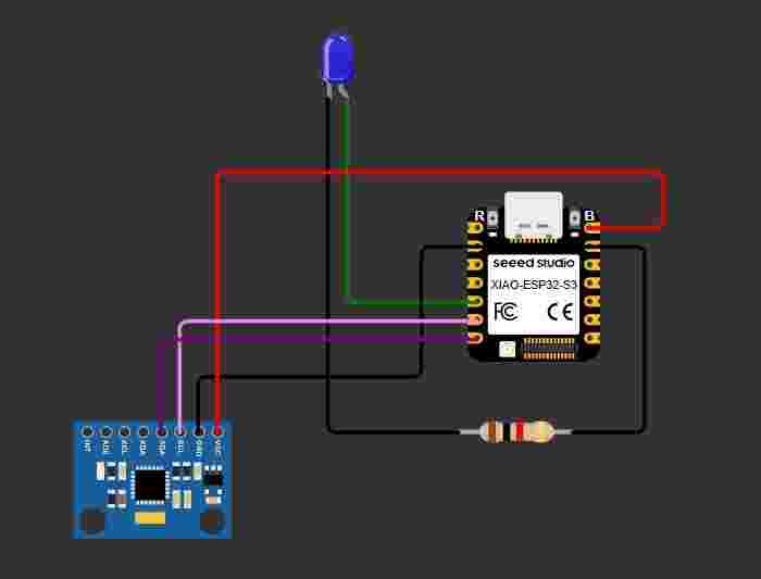
Section 1: Library and Hardware Definitions.
This section includes the Wire.h library for I2C communication and defines the I2C address for the MPU6050 (0x68). It also specifies the pins for the LED and the I2C interface (SDA and SCL) assigned to the board.
#include <Wire.h>

#define MPU_ADDR 0x68

#define LED_PIN D4
#define SCL_PIN D5
#define SDA_PIN D6
Section 2: System Setup and Sensor Wake-up.
The setup function configures the LED pin as an output and initializes the Serial communication. It starts the I2C bus with the defined pins and sends a command to register 0x6B to wake up the MPU6050, as it starts in sleep mode by default.
void setup() {
pinMode(LED_PIN, OUTPUT);
Serial.begin(115200);
Wire.begin(SDA_PIN, SCL_PIN);
Wire.beginTransmission(MPU_ADDR);
Wire.write(0x6B);
Wire.endTransmission();

Serial.println("MPU6050 initialized");
}
Section 3: Data Request and Raw Reading.
Inside the loop, the code requests 6 bytes of data starting from register 0x3B (Accelerometer X-axis). It then uses bit-shifting to combine the high and low bytes for each of the three axes (X, Y, and Z) into 16-bit integers.
void loop() {
int16_t accX, accY, accZ;

Wire.beginTransmission(MPU_ADDR);
Wire.write(0x3B);
Wire.endTransmission(false);
Wire.requestFrom(MPU_ADDR, 6, true);

accX = Wire.read() << 8 | Wire.read();
accY = Wire.read() << 8 | Wire.read();
accZ = Wire.read() << 8 | Wire.read();

float ax = (float)accX;
float ay = (float)accY;
float az = (float)accZ;
Section 4: Movement Calculation and Normalization.
The code calculates the magnitude of the acceleration vector using the square root of the sum of squares. This value is constrained and normalized between 16000 and 50000 to generate a movement percentage (0-100%).
float movement = sqrt(ax * ax + ay * ay + az * az);
float minVal = 16000;
float maxVal = 50000;
movement = constrain(movement, minVal, maxVal);
float normalized = (movement - minVal)/(max_val - minVal);
normalized = constrain(normalized, 0.0, 1.0);
int movementPercent = normalized * 100;
Section 5: Output and Threshold Logic. Finally, the movement percentage is printed to the Serial Monitor. If the detected movement exceeds 30%, the LED is turned on (HIGH); otherwise, it is turned off (LOW). A delay of 200ms is added to stabilize the readings.
Serial.print("Movement (%): ");
Serial.println(movementPercent);

if (movementPercent > 30){
digitalWrite(LED_PIN, HIGH);
} else {
digitalWrite(LED_PIN, LOW);
}

delay(200);
}
Section: Video Demonstration. This video shows the real-time interaction between the MPU6050 sensor and the XIAO board. You can observe how the LED triggers when the movement magnitude exceeds the defined threshold.
Comparing C++ and Python highlights the difference between low-level and high-level programming approaches. C++ provides more control over hardware and performance, making it ideal for embedded systems and real-time applications, while Python offers simpler syntax and faster development, which is useful for prototyping and data processing. Understanding both languages helps choose the right tool depending on the project requirements, balancing efficiency and ease of implementation.