Final Project
Final Project
Process
Documentation of the development process for my air quality sensor project, organized by spiral development phases, from initial component testing to full system integration.
Final Project
Documentation of the development process for my air quality sensor project, organized by spiral development phases, from initial component testing to full system integration.
After completing all the planning for the system integration, I began working on my final project. In the end, I carried out the spiral phases slightly differently than originally planned due to time constraints and the weekly deliverables.
Spiral Development
I started doing my tasks a bit differently from how I had originally planned them, in order to meet the remaining weekly Fab deadlines while also developing my final project. For this reason, I began by testing the servo motor, as I was not sure whether to use that actuator or a DC motor. I did this as part of my Outputs week.
Once I had all the components I was going to use, I made an architecture diagram for the project and used it as the basis for PCB No. 2. After completing it, I started running tests with the programming for my ENS 160 + AHT2 sensor. The entire process can be found in the "PCB N02" and "PROGRAMMING" folders of my Networking and Communications week.
During the same week, I tested the I2C programming language and built the web interface for my project. I had originally planned to do this in Phase 3 of the spiral, but I moved it forward in order to complete the Networking & Communications week deliverable.
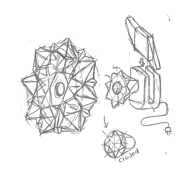
Afterwards, I started exploring different ways to physically display air quality. I had the idea of using a flower shape, since I liked the concept of it opening and closing. I also thought about showing air quality through pneumatic suction systems, inspired by a video about air-powered segment displays.
However, while exploring options during the Wildcard Week, I came across kinetic origami. After reviewing references on the Fab Lab page and doing additional research, I decided this would be my physical representation of air quality. During that week I explored different origami forms, and once I found one I liked, I focused on converting the folding process into digital fabrication, using Oripa software and 3D printing on fabric. The full detailed process can be found in Week 16: Wildcard Week.
Spiral Development
I began building the mechanism, which is inspired by the iris mechanism. I started by following this Pinterest reference:
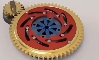
Pinterest reference: iris mechanism that inspired the project's actuation design.
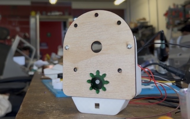
I modified it to do what I needed. When I was nearly done, I realized the small gear was going to collide with the structure. This led me to flip the structure, placing the gears underneath the mechanism. In the end, I liked the result much more after making that change. For the modeling I followed the same process and used the same tools learned during the 3D Scanning and Printing week, which I also practiced during the Machine Design week.
Video: mechanism design and modeling process in SolidWorks.
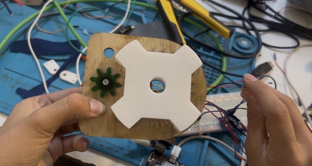
To test the functionality and the print quality, I printed a test prototype.
I realized that assembly was not straightforward. To save material and simplify the assembly process, I decided to reduce the mechanism to only 4 petals.
Video: mechanism prototype test.
I also tested assembling it with the origami. I realized that the origami base needed to be fixed to the mechanism. My solution was to use the NeoPixel cover to secure the mechanism, for this, I needed to reprint the origami mechanism with a hole.
Video: origami assembly test with the mechanism.
Once I had the first mechanism, I needed to connect it to the servo motor, so I moved on to designing the gears. I began by studying transmission ratios and worked through exercises to calculate the number of teeth needed. As I calculated more variants, I started to understand the relationships between rotation angles, tooth count, and gear diameters. For example, I realized I could make the servo rotate less in order to give it a larger gear, since at first the gear was coming out very small. These are the notes I took:
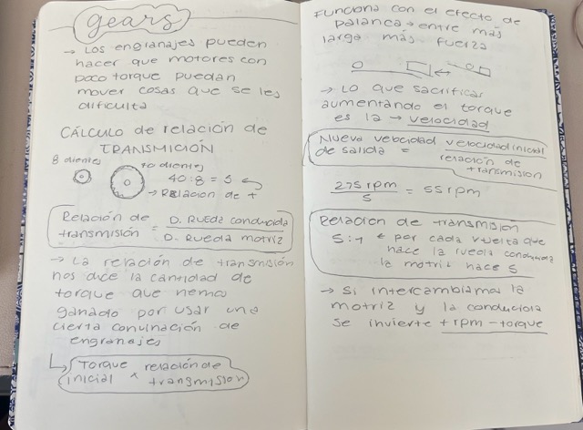
Handwritten notes: gear transmission ratio calculations and relationships between angles, tooth count, and diameter.
I kept experimenting to find the ideal gear configuration, I wanted to find one without too many decimal values, that respected the dimensions I needed, and delivered the correct rotation angle. I ended up with the following values:
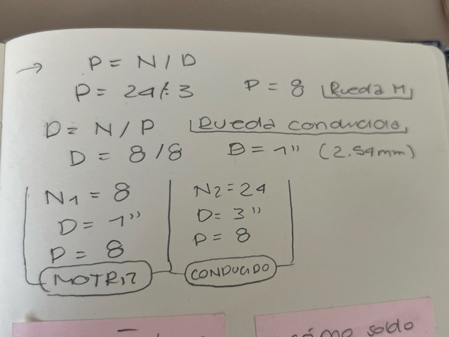
Final gear calculation results with the chosen parameters.
I then found a program: Free Gear Generator that automatically generates the DXF or SVG for a gear based on the values I had calculated. I experimented further and ended up adjusting some values to keep everything as simple as possible. I used the following parameters:
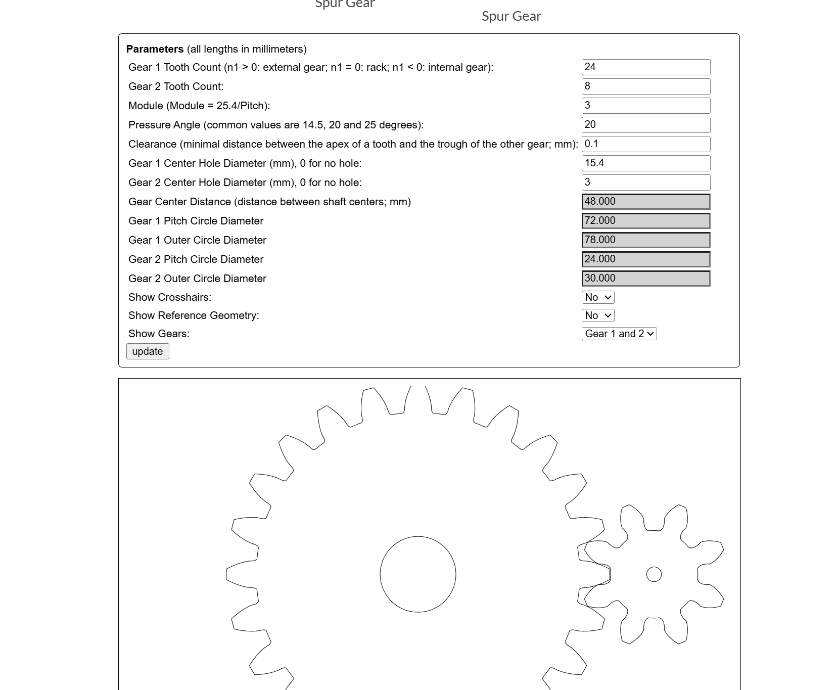
Free Gear Generator (Evolvent Design) — program interface with the gear configuration.
I then exported the DXF file and laser-cut the pieces in MDF to verify everything was correct. I switched to cutting that part with the laser cutter instead of 3D printing, as it is faster and the gear is a flat piece.
I started making the gears from 3 mm MDF scraps, but when testing them I realized the screw joining the small gear to the servo motor was preventing the mechanism from moving.
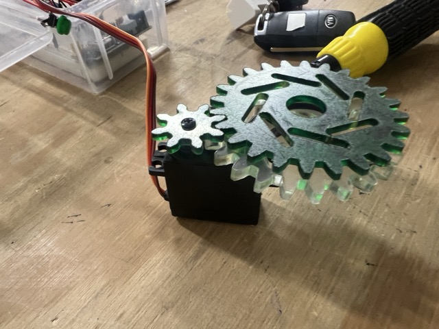
I had some 5 mm acrylic scraps available. I made the final large gear from 5 mm acrylic and the small gear from 3 mm acrylic. The image below shows all three gears I made on the servo — the transparent large one and the green small one are the versions I used in the end.
Spiral Development
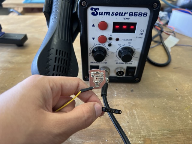
Before running tests with the servo, I needed to complete the pogo pin section, as this was how the components would connect to the main PCB.
To place the pogo pins, I made a copper board with holes that allowed me to solder the pogo pins in position, directing them straight to the required traces. The pogo pins were ultimately used for communication between the module and the servo, the NeoPixel, and the external button.
At first, I2C communication was also going to be connected via pogo pins. However, due to their high cost, I decided to use male and female pin headers instead, so the sensor can be replaced quickly and the prototype is more affordable to replicate.
While reviewing my PCB connections, I discovered that the I2C pins were in the wrong order coming out of the PCB, which prevented me from connecting the sensor directly to the board.
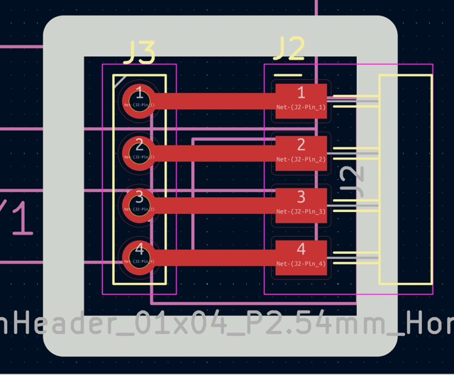
Because of this, I had to make an additional module that corrected the pin order. This is how it turned out:
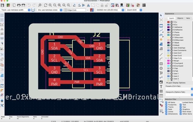
KiCad design of the additional module to correct the I2C pin order.
I also took the opportunity to make the other two boards I was missing: the pin header boards, which have outputs for the servo, a NeoPixel, and a button I plan to use to turn on the light. To fabricate them I used the Monofab and followed the same process as in Week 8 — Electronics Production.
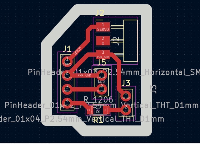
Extra PCB No. 1 — pin header connections.
Extra PCB No. 2 — pin header connections.
I also soldered cables to the remaining components to start working on the general programming for what was still missing from the board. Once everything was connected, I assembled it all on a breadboard to start integrating everything into a unified codebase.
I used the same programming approach as always, since I am still developing my programming skills, I asked an AI to help me build the code step by step. The following was my prompt:
Programming Prompt
Act as an electronics and programming expert. I want you to help me write the complete code for my final project to avoid burning anything or encountering any problems, and to ensure everything flows in the best way possible. For my project I need you to, starting from the existing code, add the programming for the new components without changing what already works for my MQTT communication. This is what I need to add:

Connections:

Sensor
  SDA Sensor → D4 (ESP32-C6)
  SCL Sensor → D5 (ESP32-C6)
  VCC Sensor → VCC (ESP32-C6)
  GND Sensor → GND (ESP32-C6)

Servo motor MG995:
  PWM MG995  → Pin D0 (ESP32-C6)
  VCC MG995  → VCC 5V (External supply)
  GND MG995  → GND (External supply)
  GND MG995  → GND (ESP32-C6)

NeoPixel:
  Din NeoPixel → D1 (ESP32-C6)
  VCC NeoPixel → VCC 5V (External supply)
  GND NeoPixel → GND (ESP32-C6)
  GND NeoPixel → GND (External supply)

Button:
  Din Button → Pin D2 (ESP32-C6) — has a 10 kΩ resistor
  GND Button → GND (ESP32-C6)

LiPo Battery 3.3 V, 2000 mAh (connected directly to the back XIAO battery pins — not connected for this test):
  PWR Battery → PWR (ESP32-C6)
  GND Battery → GND (ESP32-C6)

Behavior:
The sensor sends humidity, temperature, VOC, and CO2 data. From there we define good, medium, or bad air quality:
  VOC good   + CO2 good    = good air quality
  VOC good   + CO2 medium  = medium air quality
  VOC medium + CO2 good    = medium air quality
  VOC medium + CO2 medium  = medium air quality
  VOC bad    + CO2 medium  = bad air quality
  VOC medium + CO2 bad     = bad air quality
  VOC bad    + CO2 bad     = bad air quality

Servo behavior based on air quality:
  If quality becomes medium in any value → close to 80%
  If both values reach medium → close to 100% = 80° of servo rotation (must never exceed this angle)
  When quality is good → return to initial position

NeoPixel (uses outdoor API data for color):
  Good AQI   = warm yellow
  Medium AQI = warm orange
  Bad AQI    = warm red
  Button on D2 toggles the NeoPixel on/off.

Pin D3 has a red LED that turns on when air quality is bad.

For the initial simulation/test: pressing the button on D2 should close the servo and turn on the LED.
I started by writing two test codes: one to verify the servo and button connections, and another for the NeoPixel.
This code toggles the servo between open (0°) and closed (170°) each time the button on D2 is pressed, with smooth step-by-step movement and software debouncing:
#include <ESP32Servo.h>

#define SERVO_PIN   D0
#define BUTTON_PIN  D2

#define ANGLE_OPEN    0
#define ANGLE_CLOSED  170  // Changed from 80 to 170

#define STEP_DELAY_MS  15

Servo myServo;

bool servoIsClosed = false;
int  currentAngle  = ANGLE_OPEN;
bool actionPending = false;

int  lastRawReading  = HIGH;
bool stableState     = HIGH;
unsigned long lastBounceTime = 0;
const unsigned long DEBOUNCE_MS = 50;

void moveServoSmooth(int from, int to);
void checkButton();

void setup() {
  Serial.begin(115200);
  delay(1000);

  Serial.println(F("================================================"));
  Serial.println(F("  XIAO ESP32-C6 | STEP 1: Servo + Button Test  "));
  Serial.println(F("================================================"));

  pinMode(BUTTON_PIN, INPUT_PULLUP);
  Serial.println(F("[OK] Button configured at D2 (active pull-up)"));

  myServo.setPeriodHertz(50);
  myServo.attach(SERVO_PIN, 500, 2400);
  Serial.println(F("[OK] Servo MG995 configured at D0"));

  Serial.println(F("[..] Calibrating: moving servo to 0 degrees..."));
  myServo.write(ANGLE_OPEN);
  currentAngle = ANGLE_OPEN;
  delay(1500);

  Serial.println(F("[OK] Servo in OPEN position (0 degrees)"));
  Serial.println(F(""));
  Serial.println(F(">> READY - Press the button on D2 to test <<"));
  Serial.println(F("   Press 1: Closes servo (0 -> 170 degrees)"));
  Serial.println(F("   Press 2: Opens  servo (170 -> 0 degrees)"));
  Serial.println(F("================================================\n"));
}

void loop() {
  checkButton();

  if (actionPending) {
    actionPending = false;

    if (!servoIsClosed) {
      Serial.println(F("\n[BUTTON] Closing servo..."));
      moveServoSmooth(currentAngle, ANGLE_CLOSED);
      servoIsClosed = true;
      Serial.print(F("[OK] CLOSED - Final angle: "));
      Serial.print(currentAngle);
      Serial.println(F(" degrees"));

    } else {
      Serial.println(F("\n[BUTTON] Opening servo..."));
      moveServoSmooth(currentAngle, ANGLE_OPEN);
      servoIsClosed = false;
      Serial.print(F("[OK] OPEN - Final angle: "));
      Serial.print(currentAngle);
      Serial.println(F(" degrees"));
    }

    Serial.println(F("\n>> Press the button again to toggle <<"));
  }

  delay(10);
}

void checkButton() {
  int reading = digitalRead(BUTTON_PIN);

  if (reading != lastRawReading) {
    lastBounceTime = millis();
    lastRawReading = reading;
  }

  if ((millis() - lastBounceTime) > DEBOUNCE_MS) {
    bool newStable = (bool)reading;
    if (newStable != stableState) {
      stableState = newStable;
      if (stableState == LOW) {
        actionPending = true;
      }
    }
  }
}

void moveServoSmooth(int from, int to) {
  to = constrain(to, ANGLE_OPEN, ANGLE_CLOSED);  // Never exceeds 170 degrees

  int step = (to > from) ? 1 : -1;

  for (int angle = from; angle != to; angle += step) {
    myServo.write(angle);
    currentAngle = angle;
    delay(STEP_DELAY_MS);
  }

  myServo.write(to);
  currentAngle = to;
}
Video: servo motor test.
Once I confirmed the servo was moving, I placed the origami on the mechanism to test everything together.
Video: servo motor test with the origami assembled on the mechanism.
This code cycles the NeoPixel through red, green, blue, and off to verify the LED connection and color output:
#include <Adafruit_NeoPixel.h>

#define NEOPIXEL_PIN  D1
#define NUM_PIXELS    1

Adafruit_NeoPixel pixel(NUM_PIXELS, NEOPIXEL_PIN, NEO_GRB + NEO_KHZ800);

void setup() {
  Serial.begin(115200);
  delay(1000);
  Serial.println("NeoPixel Test starting...");

  pixel.begin();
  pixel.setBrightness(80);
}

void loop() {
  // Red
  Serial.println("RED");
  pixel.setPixelColor(0, pixel.Color(255, 0, 0));
  pixel.show();
  delay(1000);

  // Green
  Serial.println("GREEN");
  pixel.setPixelColor(0, pixel.Color(0, 255, 0));
  pixel.show();
  delay(1000);

  // Blue
  Serial.println("BLUE");
  pixel.setPixelColor(0, pixel.Color(0, 0, 255));
  pixel.show();
  delay(1000);

  // Off
  Serial.println("OFF");
  pixel.clear();
  pixel.show();
  delay(1000);
}
NeoPixel test: LED illuminated during the color cycle test.
Spiral Development
Once I was sure about the connections, I started soldering the pogo pins onto their respective boards that I had made previously.
I soldered the I2C correction board upside down, which made what I had fixed even worse.
I used the heat gun with flux to melt the solder, and it worked very well. Afterwards, I cleaned the board with isopropyl alcohol so it looked as good as possible.
Using a heat gun with flux to melt and remove the incorrectly soldered board.
At the same time, I started making a 3D model of the whole system so everything would integrate completely. Since I used the servo and made its own board that connects to the XIAO via pogo pins, the first step was calculating and experimenting to find the correct spot for the pogo pin. To identify the distance between the pogo and the power connector, I did several tests until I found the perfect distance.
Tests to find the correct pogo pin placement.
Final pogo pin distance confirmed.
Subsequently, I took the measurements of the PCB with the sensor attachment and started modeling the complete container. I made some openings in it to let the air pass through and create a chimney effect. It also helped that, since it is connected via pin headers, the component is suspended, which improves the air quality reading.
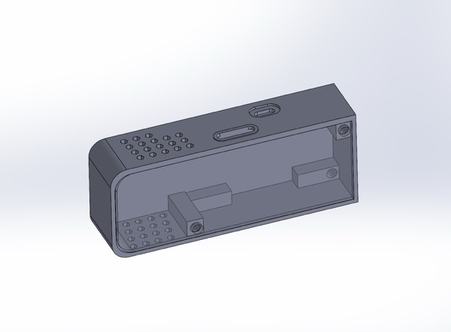
3D model of the sensor container with air openings create a chimney effect for more accurate readings.
To ensure good system integration and avoid short circuits, I made a 3D-printed piece that separates the PCB from the LiPo battery. I had to remake it 3 times because I made mistakes in small details, like the height of the pogo pin slot.
Once that entire part was correct, I started making the lid for the sensor module. Initially, I started making it using 3D printing; however, since it is a flat piece, it is more efficient to use laser cutting. I decided to make it with some acrylic scraps I had, which gave it a very nice look. I also engraved my bee logo on it. For the acrylic parameters, I used the same ones as the 3mm and 5mm MDF. You can find the table in the "Computer-Controlled Machining" week.
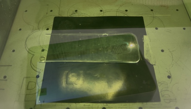
Laser engraving of the bee logo on the acrylic sensor module lid.
After all the tests, and once I managed to get everything in place, this was the final result of the sensor module assembly.
Video: final sensor module assembly.
Spiral Development
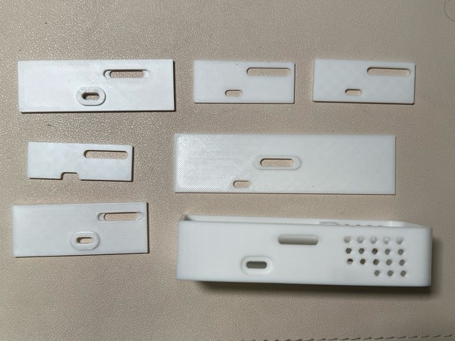
Once I had the sensor module ready, I started making the flower housing, which hid the necessary connections and allowed me to place the module on top so the whole system could work together. It was a process of a lot of trial and error. However, I did it in parts so that if I made a mistake, I wouldn't have to print everything again. Still, I think in the future it would be better to make prototypes that aren't exclusively 3D printed, since I ended up repeating several prints.
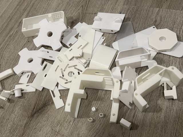
Discarded prints from the iterative housing development process.
I first did the whole SolidWorks 3D model. I used the parts I had already and added what I needed. Here is how it turned out at the end:
Complete SolidWorks 3D model of the full system housing.
To start with the module and imagine where I was going to organize the components, I built the housing in parts. I started with the bottom section, where the servo mount goes and where the mechanism would be attached with screws. For this part, I used 2 processes:
Laser Cutting
I cut the piece where I was going to screw the whole mechanism; for this, I used 4mm plywood. The process to get the DXF for this piece was simple. The model I had made previously with the mechanism was very useful. Based on the measurements I got from that model, I started making the plywood part. It was very helpful to do an assembly in SolidWorks to make sure that part would fit well. At first, I made one with the hole for the button directly on the plywood, but then I experimented, and it seemed more aesthetic and intuitive to put it on the bottom part.
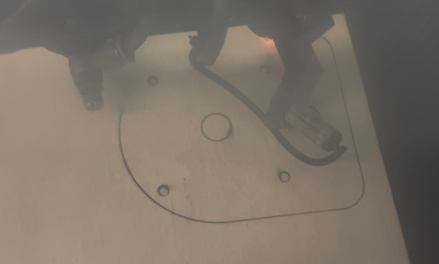
Laser cut plywood — mechanism mount base.
Fit test with the mechanism assembly.
3D Printing
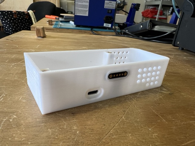
The entire back part that would contain the cables and keep the mechanism secure was 3D printed. I started by doing a small test that included the place for the button and where the servo would rest.
First 3D print test — back section with button and servo placement.
For the housing, I wanted the servo motor to have a specific place so it wouldn't move and the mechanism would work flawlessly. Downloading a 3D model of the servo from the internet was very helpful. I downloaded the servo solid file here: MG995 Servo Motor files — 3D CAD Model Library | GrabCAD.
Once I verified that the servo's height and position were correct, I modeled the rest of the housing and 3D printed everything.
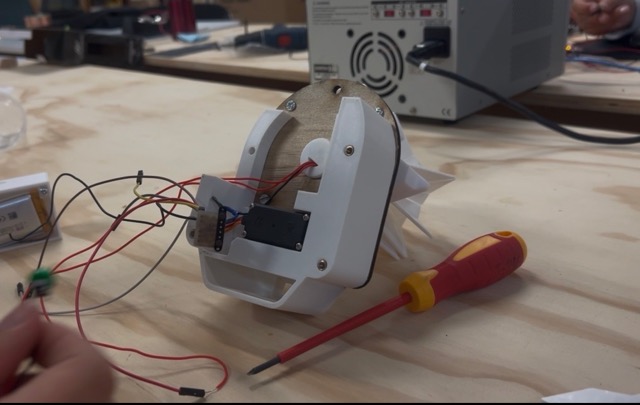
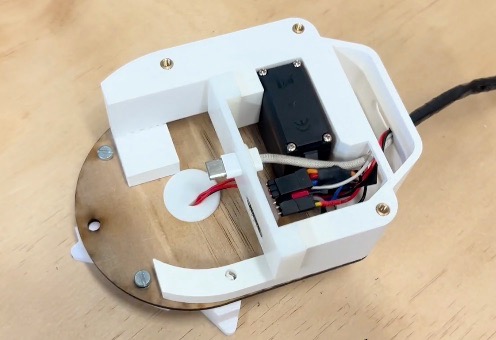
Final 3D printed housing with all components integrated.
Spiral Development
Now that I knew how the packaging would be arranged, I started organizing the cables properly. This was one of the most complicated parts, as I didn't know exactly how to fit everything in nicely.
I did tests to make the process more efficient and to ensure that all pieces would assemble well in the end. Once I had all the connections with the complete cables, I tested that everything worked properly. When I confirmed it was all good, I started cutting the cables and joining them to their respective connections using solder and heat shrink tubing (to ensure there were no short circuits). This is the before and after of how the connections looked.
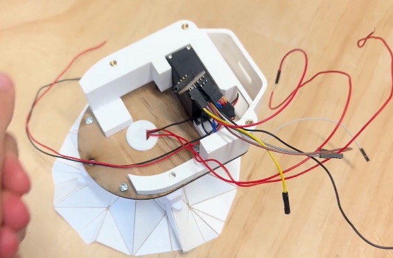
Before: cables before organization and shortening.
After: cables shortened, soldered, and secured with heat shrink tubing.
This is a video of how the assembly of my final project looks. After doing it several times, I was able to do it much faster, but in the future, I would like to make the assembly of the mechanism simpler.
Video: full project assembly process.
Once everything was well organized, I did a test with the whole assembly. This was the first video that came out.
Video: first complete system test.
To do this test, I used this code, which makes the LED turn on when I press the button, and as soon as I blow on it and it detects bad air quality, it closes.
#include#include #define SERVO_PIN D0 #define NEOPIXEL_PIN D1 #define BUTTON_PIN D2 #define ANGLE_OPEN 0 #define ANGLE_CLOSED 120 #define STEP_DELAY_MS 15 #define NUM_PIXELS 1 #define BRIGHTNESS 60 const uint32_t COLOR_GOOD = Adafruit_NeoPixel::Color(255, 160, 0); const uint32_t COLOR_MEDIUM = Adafruit_NeoPixel::Color(255, 70, 0); const uint32_t COLOR_BAD = Adafruit_NeoPixel::Color(150, 0, 0); Servo myServo; Adafruit_NeoPixel pixel(NUM_PIXELS, NEOPIXEL_PIN, NEO_GRB + NEO_KHZ800); bool systemActive = false; int currentAngle = ANGLE_OPEN; bool actionPending = false; int lastRawReading = HIGH; bool stableState = HIGH; unsigned long lastBounceTime = 0; const unsigned long DEBOUNCE_MS = 50; void activateSystem(); void deactivateSystem(); void moveServoSmooth(int from, int to); void checkButton(); void setup() { Serial.begin(115200); delay(1000); pinMode(BUTTON_PIN, INPUT_PULLUP); pixel.begin(); pixel.setBrightness(BRIGHTNESS); pixel.clear(); pixel.show(); // la libreria Servo estandar no usa setPeriodHertz myServo.attach(SERVO_PIN, 500, 2400); myServo.write(ANGLE_OPEN); currentAngle = ANGLE_OPEN; delay(1500); Serial.println("Listo, presiona D2 para abrir y cerrar la flor"); } void loop() { checkButton(); if (actionPending) { actionPending = false; if (!systemActive) { activateSystem(); } else { deactivateSystem(); } } delay(10); } void activateSystem() { Serial.println("Cerrando flor..."); moveServoSmooth(currentAngle, ANGLE_CLOSED); pixel.setPixelColor(0, COLOR_GOOD); pixel.show(); systemActive = true; Serial.println("Flor cerrada, LED encendido"); } void deactivateSystem() { Serial.println("Abriendo flor..."); moveServoSmooth(currentAngle, ANGLE_OPEN); pixel.clear(); pixel.show(); systemActive = false; Serial.println("Flor abierta, LED apagado"); } void moveServoSmooth(int from, int to) { to = constrain(to, ANGLE_OPEN, ANGLE_CLOSED); int step = (to > from) ? 1 : -1; for (int angle = from; angle != to; angle += step) { myServo.write(angle); currentAngle = angle; delay(STEP_DELAY_MS); } myServo.write(to); currentAngle = to; } void checkButton() { int reading = digitalRead(BUTTON_PIN); if (reading != lastRawReading) { lastBounceTime = millis(); lastRawReading = reading; } if ((millis() - lastBounceTime) > DEBOUNCE_MS) { bool newStable = (bool)reading; if (newStable != stableState) { stableState = newStable; if (stableState == LOW) actionPending = true; } } }
During my final tests, when everything was nicely in place and right before recording my final video, I accidentally connected the servo motor backwards. This broke it and forced me to open everything up again, cut the cables of the old servo, and replace the connections with those of a new servo.
Another big mistake I made during the process was when trying to secure the USB connector to the 3D print to power the XIAO. I was recommended to use superglue (kola loka), which doesn't conduct electricity. But when I applied it, the glue seeped into the hole of the Xiao's male USB-C connection, making it unable to receive power or data. Because of this, I had to carefully desolder it with the heat gun and replace it with a new one.
Another major problem I had at the beginning was that the humidity sensor of my air quality sensor got blocked and stopped working. For this final delivery, I bought a new one to see if it was a general sensor problem or just mine. In the end, the new one worked perfectly. I recommend that if you use the same sensor as me, try not to exhale directly onto it so you don't block the humidity sensor.
Finally, after solving all the problems, I got the sensor to work exactly the way I wanted. In this test, I'm blowing soldering fumes into it so it detects the air quality with these gases.
Video: final air quality detection test with soldering fumes.
Spiral Development
For this final phase, I started testing my device. For this, I needed to integrate the MQTT communication part I had done previously into the earlier code. Since I had little time left and wanted to avoid errors, I had Claude combine the previous code with the MQTT and the new one.
This was the final code:
#include#include #include #include #include #include #include #include const char* ssid = "YOUR_SSID"; const char* password = "YOUR_PASSWORD"; const char* mqtt_server = "broker.hivemq.com"; const char* topic_eco2 = "nicole/monitor/eco2"; const char* topic_tvoc = "nicole/monitor/tvoc"; const char* topic_temperature = "nicole/monitor/temperatura"; const char* topic_humidity = "nicole/monitor/humedad"; // API de calidad del aire exterior (Puebla) const char* owm_api_key = "YOUR_API_KEY"; const float LAT = 19.0414; const float LON = -98.2063; #define SERVO_PIN D0 #define NEOPIXEL_PIN D1 #define BUTTON_PIN D2 #define ANGLE_OPEN 0 #define ANGLE_MEDIUM 80 #define ANGLE_CLOSED 120 #define STEP_DELAY_MS 12 #define NUM_PIXELS 1 #define BRIGHTNESS 60 #define BLINK_INTERVAL 400 // umbrales de calidad segun eCO2 #define ECO2_GOOD 600 #define ECO2_MEDIUM 1000 #define COLOR_YELLOW_WARM Adafruit_NeoPixel::Color(255, 160, 0) #define COLOR_GREEN Adafruit_NeoPixel::Color( 0, 200, 0) #define COLOR_ORANGE Adafruit_NeoPixel::Color(255, 140, 0) #define COLOR_RED Adafruit_NeoPixel::Color(180, 0, 0) enum AirQuality { AIR_GOOD, AIR_MEDIUM, AIR_BAD, AIR_UNKNOWN }; WiFiClient espClient; PubSubClient mqttClient(espClient); ScioSense_ENS160 ens160(0x53); Adafruit_AHTX0 aht21; Servo myServo; Adafruit_NeoPixel pixel(NUM_PIXELS, NEOPIXEL_PIN, NEO_GRB + NEO_KHZ800); AirQuality lastLocalQuality = AIR_UNKNOWN; AirQuality outdoorAirQuality = AIR_UNKNOWN; int currentAngle = ANGLE_OPEN; // boton bool actionPending = false; bool buttonLedActive = false; int lastRawReading = HIGH; bool stableState = HIGH; unsigned long lastBounceTime = 0; const unsigned long DEBOUNCE_MS = 50; // parpadeo para calidad media bool blinkOn = false; unsigned long lastBlinkMs = 0; unsigned long lastSensorMs = 0; unsigned long lastApiMs = 0; const unsigned long SENSOR_INTERVAL_MS = 2000; const unsigned long API_INTERVAL_MS = 60000; void setup_wifi(); void reconnect_mqtt(); void readAndPublish(); AirQuality classifyAir(uint16_t eco2); void applyQuality(AirQuality q); void updateLED(); void moveServoSmooth(int from, int to); void checkButton(); void fetchOutdoorAQI(); AirQuality parseAQI(int aqi); void setup() { Serial.begin(115200); delay(1000); pinMode(BUTTON_PIN, INPUT_PULLUP); pixel.begin(); pixel.setBrightness(BRIGHTNESS); pixel.clear(); pixel.show(); myServo.setPeriodHertz(50); myServo.attach(SERVO_PIN, 500, 2400); myServo.write(ANGLE_OPEN); currentAngle = ANGLE_OPEN; delay(800); Wire.begin(D4, D5); if (!aht21.begin()) { Serial.println("Error: AHT21 no encontrado"); while (1) delay(500); } if (!ens160.begin()) { Serial.println("Error: ENS160 no encontrado"); while (1) delay(500); } ens160.setMode(ENS160_OPMODE_STD); setup_wifi(); mqttClient.setServer(mqtt_server, 1883); fetchOutdoorAQI(); Serial.println("Sistema listo"); } void loop() { if (!mqttClient.connected()) reconnect_mqtt(); mqttClient.loop(); checkButton(); if (actionPending) { actionPending = false; buttonLedActive = !buttonLedActive; if (buttonLedActive) { pixel.setPixelColor(0, COLOR_YELLOW_WARM); pixel.show(); } else { updateLED(); } } // parpadeo naranja cuando el aire es regular if (!buttonLedActive && lastLocalQuality == AIR_MEDIUM) { if (millis() - lastBlinkMs >= BLINK_INTERVAL) { lastBlinkMs = millis(); blinkOn = !blinkOn; pixel.setPixelColor(0, blinkOn ? COLOR_ORANGE : 0); pixel.show(); } } if (millis() - lastSensorMs >= SENSOR_INTERVAL_MS) { lastSensorMs = millis(); readAndPublish(); } if (millis() - lastApiMs >= API_INTERVAL_MS) { lastApiMs = millis(); fetchOutdoorAQI(); } } void setup_wifi() { Serial.print("Conectando a WiFi"); WiFi.begin(ssid, password); while (WiFi.status() != WL_CONNECTED) { delay(500); Serial.print("."); } Serial.println("\nWiFi conectado: " + WiFi.localIP().toString()); } void reconnect_mqtt() { while (!mqttClient.connected()) { Serial.print("Conectando MQTT..."); String id = "XIAO_C6_Nicole_" + String(random(0xffff), HEX); if (mqttClient.connect(id.c_str())) { Serial.println(" listo"); } else { Serial.print(" fallo rc="); Serial.print(mqttClient.state()); Serial.println(", reintentando en 3s"); delay(3000); } } } void readAndPublish() { sensors_event_t evtHum, evtTemp; aht21.getEvent(&evtHum, &evtTemp); float temperature = evtTemp.temperature; float humidity = evtHum.relative_humidity; ens160.set_envdata210( (uint16_t)((temperature + 273.15f) * 64.0f), (uint16_t)(humidity * 512.0f) ); if (!ens160.measure(true)) { Serial.println("ENS160 esperando lectura..."); return; } uint16_t eco2 = ens160.geteCO2(); uint16_t tvoc = ens160.getTVOC(); Serial.printf("Temp: %.1f°C Hum: %.1f%% eCO2: %u ppm TVOC: %u ppb\n", temperature, humidity, eco2, tvoc); char buf[12]; sprintf(buf, "%u", eco2); mqttClient.publish(topic_eco2, buf); sprintf(buf, "%u", tvoc); mqttClient.publish(topic_tvoc, buf); sprintf(buf, "%.1f", temperature); mqttClient.publish(topic_temperature, buf); sprintf(buf, "%.1f", humidity); mqttClient.publish(topic_humidity, buf); AirQuality q = classifyAir(eco2); if (q != lastLocalQuality) { applyQuality(q); lastLocalQuality = q; } } AirQuality classifyAir(uint16_t eco2) { if (eco2 < ECO2_GOOD) return AIR_GOOD; if (eco2 < ECO2_MEDIUM) return AIR_MEDIUM; return AIR_BAD; } void applyQuality(AirQuality q) { int targetAngle; switch (q) { case AIR_GOOD: targetAngle = ANGLE_OPEN; Serial.println("Aire bueno, flor abierta"); break; case AIR_MEDIUM: targetAngle = ANGLE_MEDIUM; blinkOn = true; lastBlinkMs = millis(); Serial.println("Aire regular, flor a mitad"); break; case AIR_BAD: default: targetAngle = ANGLE_CLOSED; Serial.println("Aire malo, flor cerrada"); break; } moveServoSmooth(currentAngle, targetAngle); if (!buttonLedActive) updateLED(); } void updateLED() { switch (lastLocalQuality) { case AIR_GOOD: pixel.setPixelColor(0, 0); pixel.show(); break; case AIR_MEDIUM: pixel.setPixelColor(0, COLOR_ORANGE); pixel.show(); break; case AIR_BAD: { // color segun calidad exterior que devuelve la API uint32_t color; switch (outdoorAirQuality) { case AIR_GOOD: color = COLOR_GREEN; break; case AIR_MEDIUM: color = COLOR_ORANGE; break; default: color = COLOR_RED; break; } pixel.setPixelColor(0, color); pixel.show(); break; } default: pixel.setPixelColor(0, 0); pixel.show(); break; } } void moveServoSmooth(int from, int to) { to = constrain(to, ANGLE_OPEN, ANGLE_CLOSED); int step = (to > from) ? 1 : -1; for (int angle = from; angle != to; angle += step) { myServo.write(angle); currentAngle = angle; delay(STEP_DELAY_MS); } myServo.write(to); currentAngle = to; } void checkButton() { int reading = digitalRead(BUTTON_PIN); if (reading != lastRawReading) { lastBounceTime = millis(); lastRawReading = reading; } if ((millis() - lastBounceTime) > DEBOUNCE_MS) { bool newStable = (bool)reading; if (newStable != stableState) { stableState = newStable; if (stableState == LOW) actionPending = true; } } } void fetchOutdoorAQI() { if (WiFi.status() != WL_CONNECTED) return; char url[180]; snprintf(url, sizeof(url), "http://api.openweathermap.org/data/2.5/air_pollution?lat=%.4f&lon=%.4f&appid=%s", LAT, LON, owm_api_key); HTTPClient http; http.begin(url); int code = http.GET(); if (code == 200) { String payload = http.getString(); int idx = payload.indexOf("\"aqi\":"); if (idx != -1) { int aqi = payload.charAt(idx + 6) - '0'; outdoorAirQuality = parseAQI(aqi); Serial.printf("AQI exterior: %d\n", aqi); if (lastLocalQuality == AIR_BAD && !buttonLedActive) updateLED(); } } else { Serial.printf("Error al obtener AQI: HTTP %d\n", code); } http.end(); } AirQuality parseAQI(int aqi) { if (aqi <= 2) return AIR_GOOD; if (aqi == 3) return AIR_MEDIUM; return AIR_BAD; }
After some tests, I got it to work. This is the final video of the sensor:
Video: final project working demo.
Once everything worked, I started editing my final video in Canva; you can find it on the previous page, along with the poster.
This has been one of the hardest courses I've taken; it taught me the importance of time management and documentation. However, now that I've finished this, I feel very proud of my progress and everything I achieved and learned during these weeks. I realized that I can learn anything I want, I just need to dedicate time to it, and it helps a lot to talk to people who have already learned what you're trying to figure out.
I want to thank my friends Majo, Ana Sofia, and Greayshell, who accompanied me throughout the process and helped me a lot with their documentation; my fellow engineers, who helped me on many occasions (and several became my friends); my local instructors: Beto, Oliver, Rafa, Aristarco, Charly, Raul, and Mari Cruz; my global instructors; and above all, my family and my boyfriend, who accompanied and supported me throughout the process. Thank you for always being there for me and helping me fulfill my dreams.
In electronics, it's better to be cautious. Before connecting everything, you should check that all connections are correct and that the power supply is giving the right voltage (using a multimeter); otherwise, you could end up burning several components.
Project License
// Modular Active Air Quality Monitor //
© 2026 Nicole Friederichs Espinosa //
Non-commercial use only.
This work may be reproduced, modified, distributed, performed, and displayed for non-commercial purposes only, but must acknowledge "Modular Active Air Quality Monitor" by Nicole Friederichs Espinosa. Any commercial use of this work or its derivatives, including sale, monetization, or incorporation into a product or service offered for compensation, requires prior written permission from the author.
Copyright is retained and must be preserved in all copies and derivatives. No patent, trademark, or other intellectual property rights beyond those stated here are granted; all rights not expressly granted are reserved.
This project has not been certified for electrical safety or any regulatory standard and is intended for educational and personal use only; it is provided as-is, no warranty is provided, and users accept all liability.