OPTION A
3D Print on Fabric
Printing directly onto a fabric substrate to give the structure flexibility while maintaining the rigidity of the printed geometry.
patreon.com → 3D Print on Fabric ReferenceThis week I explored kinetic origami as a digital fabrication process. Starting from research and paper prototypes, I moved through analog case studies, crease pattern design software, and digital manufacturing methods to develop a functional origami mechanism for my final project.
Here is the full documentation: theory, experimentation, 3D modeling, digital fabrication, and the final result.
Design and produce something with a digital fabrication process not covered in another assignment. Document the requirements your assignment meets and include everything necessary to reproduce it.
My first challenge was not knowing where to start, there is a lot of information available, but it can be hard to find exactly what you need. Something that has helped me a lot is following a methodology I build for each project based on its objectives. These were the main steps I followed:
What makes origami special as a manufacturing process is its energy efficiency and structural ingenuity. Calisch's thesis demonstrates how laser-cutting geometric fold patterns uses significantly less energy than traditional 3D printing, while still achieving complex 3D volume. I haven't covered this previously because prior assignments focused on traditional fabrication (adding or cutting away material). This is my first time exploring kinetic origami, where the material's geometry and folds replaces traditional hardware.
Kinetic origami uses the folds of paper as functional joints to give a structure its mechanics. In engineering, the geometric principles of origami are being used to create structures that can change shape.
For my project, I explored the Fab Lab documentation and found the thesis by Samuel Eli Calisch titled Folded Functional Foams. His analysis of how we can manufacture complex structures from flat sheets through cutting and folding was very insightful. It helped me see origami not as a toy, but as an intelligent manufacturing method that can create high-performance industrial components with remarkable efficiency. One of the points that struck me most was the environmental and energy comparison: 3D printing consumes a massive amount of energy to build objects layer by layer, whereas laser-cut origami structures are drastically more efficient (less energy, less material, much faster).
I searched for fold types that could be functional for my project. Several of these also appeared in the Calisch thesis.
After the theoretical research, I moved into hands-on exploration: analog case studies, paper prototypes, 3D printed tests, and video references. Until I found the model that fit my project.
After watching several videos of origami folds and how they looked applied to products, I could not find one that had the specific movement I was looking for, most ended up flat, not with a closing motion that resembled a flower.
Because of this I started searching for origami flowers and followed a tutorial to make a daffodil, with the goal of exploring whether I could use non-tessellation origami pieces for the project:
The model was somewhat difficult to make, and when I tested the movement I wanted to achieve with it, the structure did not allow it to flow smoothly. I discarded this piece.
To keep exploring, I 3D printed the model from Printables. At first it was a bit tricky to assemble, but I followed their tutorial and managed to put it together.
Model: Flasher Hexagon with Living Hinges
Assembly tutorial: youtube.com → Assembly Guide
During the process I noticed the print was not very resistant: when folding some sides, small holes appeared at the creases. In the end one side broke completely.
While browsing further I came across this video from Brigham Young University (BYU), which inspired me a great deal. The shapes they showed were very interesting for the flower form I was looking for.
I then searched Pinterest and built a moodboard of what I was trying to recreate. During this exploration I found origami umbrellas — the mechanism was very interesting and was exactly what I was looking for, so I followed the tutorial.
Reference: Pinterest → Origami Umbrella Tutorial
What I did not like about this model was that the parts had to be glued together. Additionally, something went wrong in my build because it did not have the full range of movement I needed. I kept searching for models.
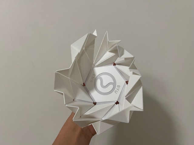
From all of these videos, I chose the one that seemed best suited for the project:
Paper Folding with Adam Williamson: Octagrammer
YouTube → Octagrammer Tutorial
I followed the tutorial and, once I had the form, I started experimenting with different configurations and movements. During this exploration I found exactly the motion I was looking for and really liked how it looked.
I once heard that you should search for 30% of the time, and once you find something that surpasses everything you have seen before and meets your expectations, you keep it. This model did exactly that. I did not choose the tessellations mentioned in the theory research because they were flat or cylindrical and did not have the motion I needed — although observing this model I noticed it does resemble the Miura-ori pattern.
I wanted to use the origami directly, just with a different sheet in my project. But when I talked to my instructor, he pointed out that the digital fabrication component was missing, and he was right. This pushed me to look for ways to improve it, especially considering that the 3D printed living hinges I had tested earlier broke easily. That is why I started looking for options for the digital fabrication. These are the ones I found:
3D Print on Fabric
Printing directly onto a fabric substrate to give the structure flexibility while maintaining the rigidity of the printed geometry.
patreon.com → 3D Print on Fabric Reference3D Printed Origami Press — Butterfly
Using a 3D printed press mold to form and crease the origami panel at precise fold lines.
3D Printed Origami Press — Butterfly referenceI unfolded the origami to see how its folds looked flat, and based on this I started tracing the model in SolidWorks. It was going well until I realized some lines were not exactly right, so I looked for another software option and found ORIPA.
ORIPA is a drawing software dedicated to designing the crease patterns of origami. It understands mountain and valley folds natively and can export to DXF and SVG for fabrication.
To use ORIPA you first need a Java Runtime Environment (JRE or JDK). I downloaded it from the Adoptium website via Homebrew.
Step 1 — Install Java via Homebrew (terminal), I used Eclipse temurin:
brew install --cask temurin@25Step 2 — Download ORIPA
Go to the ORIPA GitHub releases page and download oripa-1.79-all.jar (or the latest version).
Step 3 — Verify Java installed correctly:
java -versionStep 4 — Navigate to your Downloads folder:
cd DownloadsStep 5 — Launch ORIPA (replace with your version number):
java -jar oripa-1.79-all.jarPress Enter and the application will open automatically. For more information: github.com/oripa/oripa
I based my tracing process on this tutorial: YouTube → ORIPA Crease Pattern Tutorial
What I understood: mountain folds are the lines that fold upward, and valley folds are the ones that fold downward.
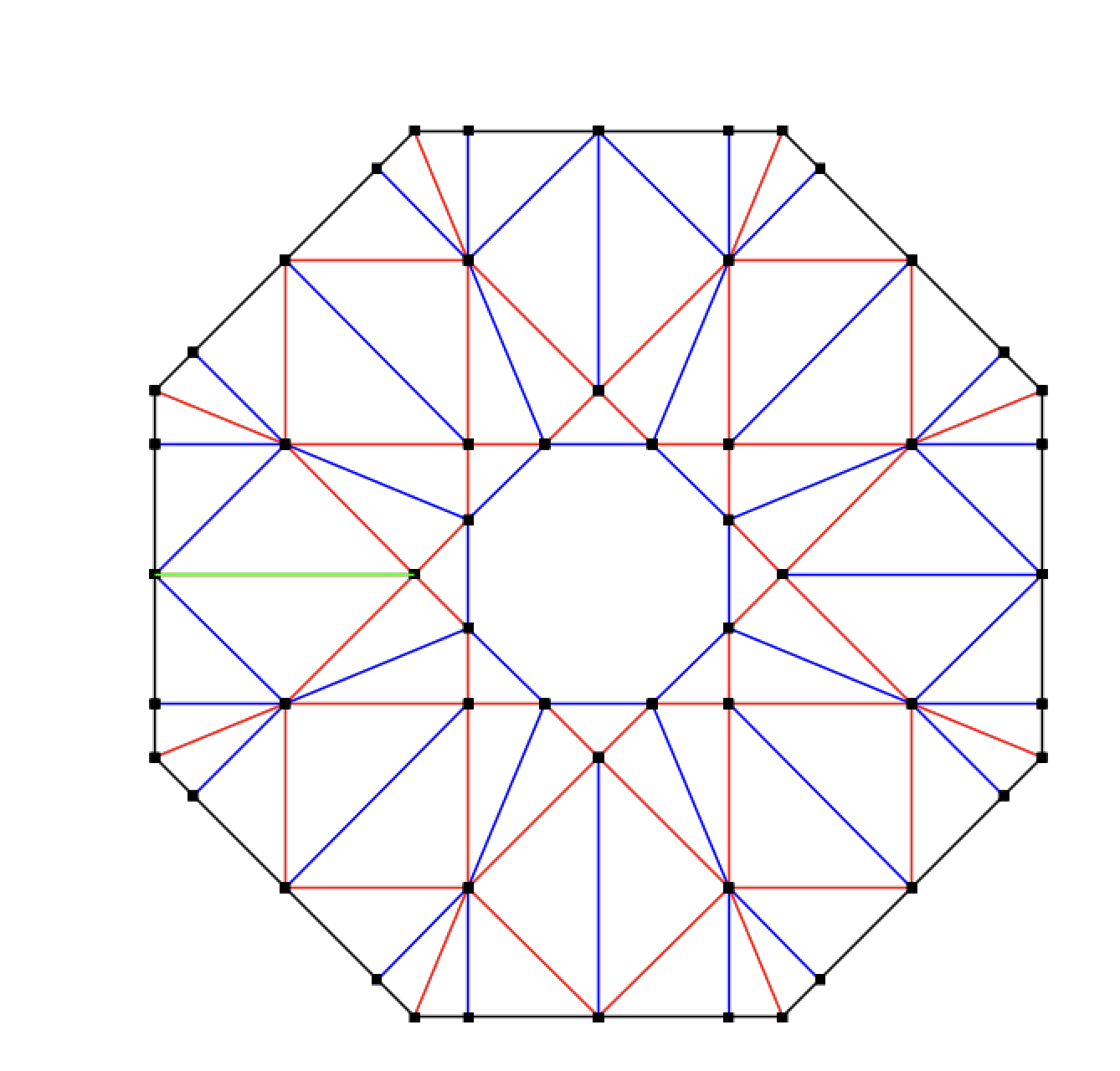
The system flagged an error when I tried to run the fold simulation. However, since all I needed was a DXF or SVG file for fabrication, I simply exported those directly — the export worked correctly, and I brought the files into the fabrication application.
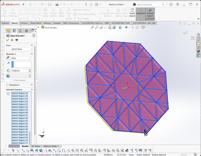
After exporting the DXF file, I started creating an STL file for printing. I did the modeling with SolidWorks. This is a video of the process for converting a DXF to a sketch in SolidWorks.
Once I finished doing this, I selected the entire sketch and applied a 0.5mm offset to both sides. Since the file was quite large and it would have taken me a while to trim the extra parts, I went straight to extruding. I scrolled down and clicked on "Selected Contour." With that command, I started extruding one by one.
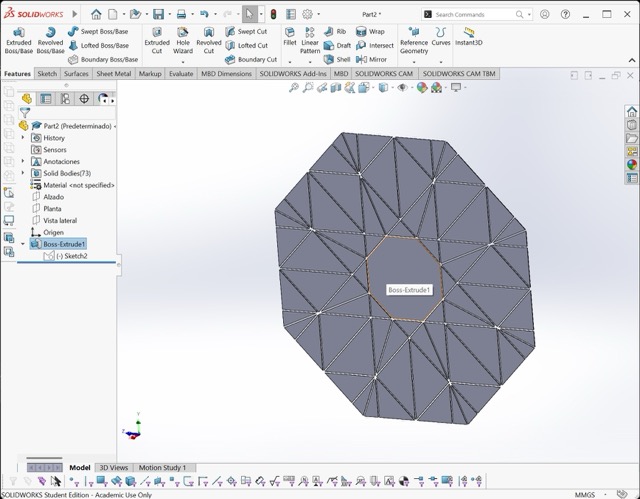
This is the final result from SolidWorks. I saved this file as an STL and began the physical manufacturing process:
For this final part I returned to the two options I had identified and decided how to proceed with manufacturing the origami panel digitally.
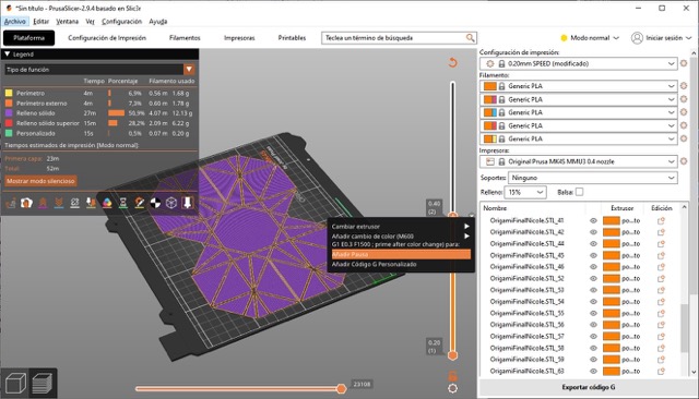
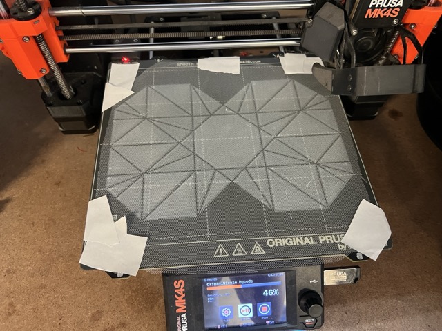
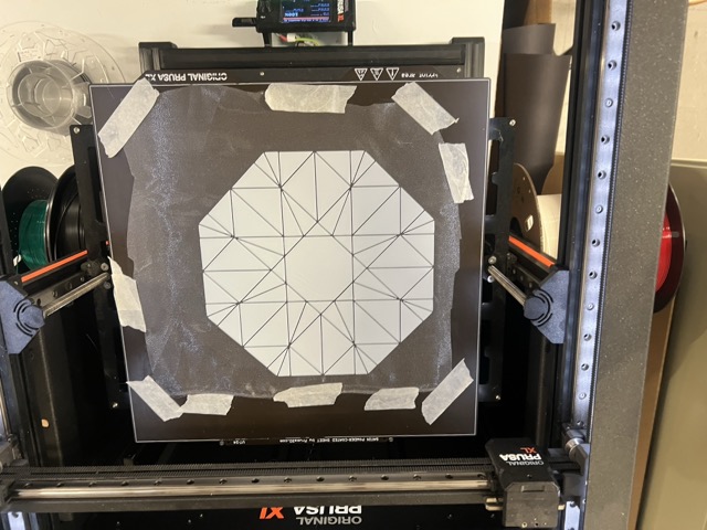
I chose to experiment with 3D printing on fabric; the process was simpler than I thought. I just opened the STL in PrusaSlicer and added a pause to be able to place the fabric. I did several tests before the final one; the tests were done with a cropped part of the model to be able to print it on the small printers, since the complete model does not fit.
I tested with 3 fabrics:
The first test went very well.
Only the Organza and Tulle worked. The print did not stick to the Pellon.
For the final model, I followed the same steps of making the file and placing the fabric during the pause. I chose to make it out of Organza because of its shine.
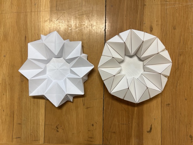
The final kinetic origami panel was produced using the 3D printing in fabric method method, based on the ORIPA crease pattern of the Octagrammer model. Below are the final images and video of the completed mechanism.

I learned a lot this week. I found the whole topic of origami very interesting, and it was very satisfying to discover the Oripa app. I'm proud of the work I did this week. However, I still need to modify a few things to adapt this origami for the final project.
Project License
// © 2026 Nicole Friederichs Espinosa //
Non-commercial use only.
This work may be reproduced, modified, distributed, performed, and displayed for non-commercial purposes only, but must acknowledge the author. Any commercial use of this work or its derivatives, including sale, monetization, or incorporation into a product or service offered for compensation, requires prior written permission from the author.
Copyright is retained and must be preserved in all copies and derivatives. No patent, trademark, or other intellectual property rights beyond those stated here are granted; all rights not expressly granted are reserved.
This project has not been certified for electrical safety or any regulatory standard and is intended for educational and personal use only; it is provided as-is, no warranty is provided, and users accept all liability.