Telemetry & Logic
Verify accurate execution of the decision matrix comparing local I2C sensor data with Wi-Fi API data without blocking the microcontroller.
This week I developed the full integration of my final project. The process gave me clarity on everything I needed to build and allowed me to think through the complete product lifecycle, from concept to packaging before any physical fabrication began.
Design and document the system integration for your final project
An indoor air quality management device that translates environmental sensor data into physical movement. The system helps users decide whether to open a window for natural ventilation or to activate an air purifier.
Design and build a modular air quality monitor that translates environmental data into physical movement through a kinetic origami panel. The system must integrate local sensor telemetry with external government data to intuitively guide the user on whether to ventilate the room naturally or use an air purifier, while allowing the sensor unit to be easily detached for portable testing across different rooms.
People often lack intuitive, real-time awareness of indoor air quality compared to outdoor conditions. In highly polluted or geographically unique areas — such as Mexico City (CDMX) with severe PM2.5 smog alerts, or Puebla with frequent volcanic ash fall — this lack of information becomes a critical health hazard. Users might open a window believing they are naturally ventilating their room, only to inadvertently draw in hazardous external pollutants, drastically worsening indoor air quality. Furthermore, traditional monitors rely on easily ignored numerical screens that lack actionable context, and being strictly tethered to a wall makes it difficult to evaluate an entire house without purchasing multiple units.
After I had a clear concept I started doing the requirements of the project, some of them were modifyed or added after the risk diagram:
Verify accurate execution of the decision matrix comparing local I2C sensor data with Wi-Fi API data without blocking the microcontroller.
Absence of material tearing, jamming, or servo stalling after repeated expansion and contraction cycles of the origami panel.
Continuous system operation, stable I2C communication, and automatic battery switchover when detaching and reattaching the portable module.
Temperature and humidity readings must remain consistent with ambient room conditions, entirely unaffected by the internal heat generated by the ESP32-C6.
The project is structured into four incremental phases, each building on the validated output of the previous one.
To begin, I identified all the components I would use and planned the connections between them. I also outlined the architecture of the interface. Below is the complete documentation of the system's electronic and software structure, risk analysis, design sketches, and packaging strategy.
The core hardware stack and the connections planned between them.
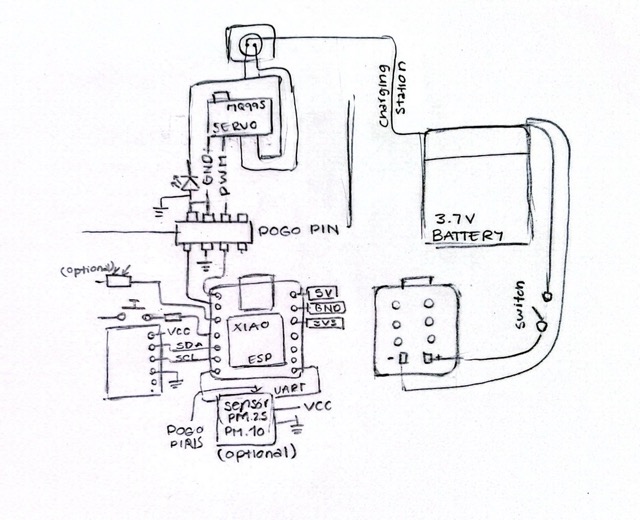
The firmware is divided into two logical layers: a backend running on the microcontroller, and a frontend served on demand to the user's browser.
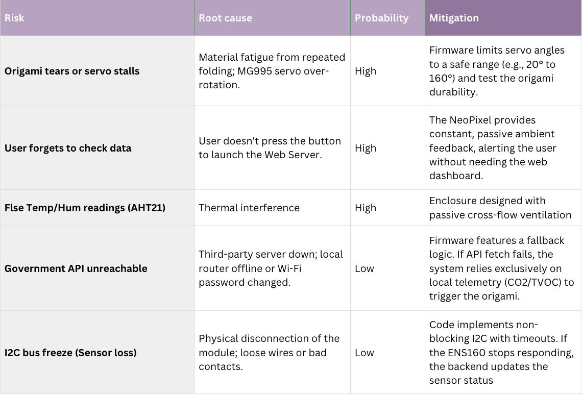
I developed a risk diagram to anticipate everything that could go wrong — staying one step ahead to prevent issues before they occur.
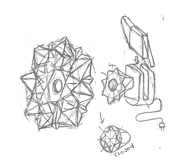
After the risk analysis, I began sketching how the entire system would be integrated, considering enclosure design and the points raised in the risk diagram. I explored several forms for the portable pod, ultimately selecting the shape that resembles the leaves of a flower.
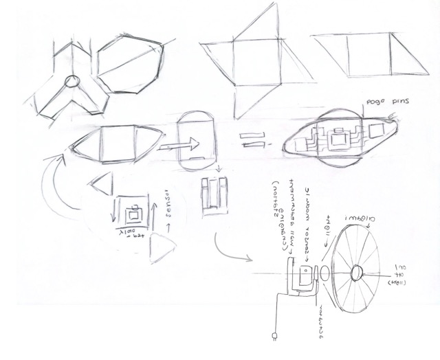
The enclosure combines 3D printed PLA for the portable pod and the actuator mechanism, with a Laser-cut triplay wood base. Joints rely on M4 screws and brass threaded inserts to ensure durability over repeated disassembly —> no adhesives are used.
The pod's geometry incorporates lower side intakes and upper exhaust vents to create passive cross-flow ventilation. This chimney effect successfully isolates the environmental sensors from the heat generated by the ESP32-C6 microcontroller.
Project License
// © 2026 Nicole Friederichs Espinosa //
Non-commercial use only.
This work may be reproduced, modified, distributed, performed, and displayed for non-commercial purposes only, but must acknowledge the author. Any commercial use of this work or its derivatives, including sale, monetization, or incorporation into a product or service offered for compensation, requires prior written permission from the author.
Copyright is retained and must be preserved in all copies and derivatives. No patent, trademark, or other intellectual property rights beyond those stated here are granted; all rights not expressly granted are reserved.
This project has not been certified for electrical safety or any regulatory standard and is intended for educational and personal use only; it is provided as-is, no warranty is provided, and users accept all liability.