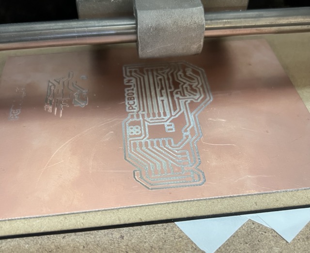
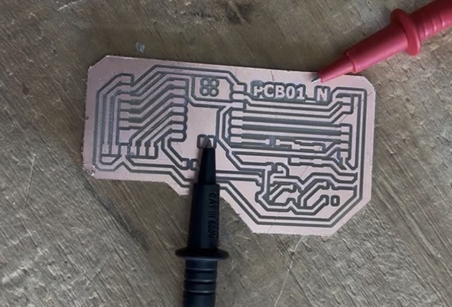
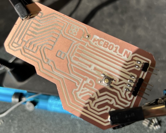
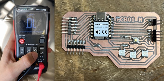
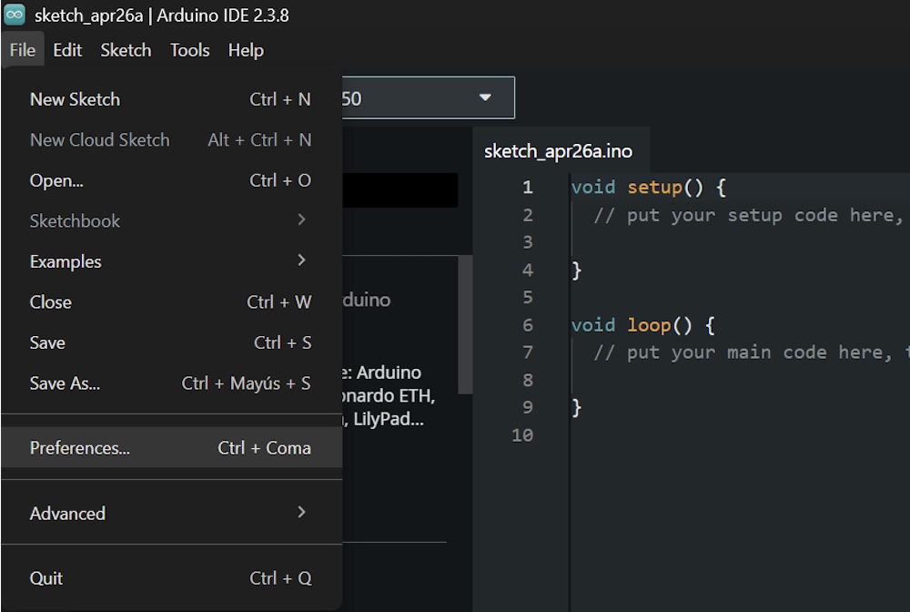
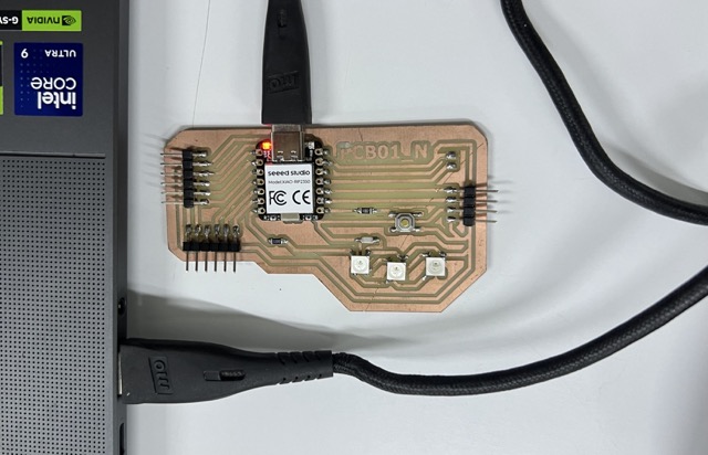
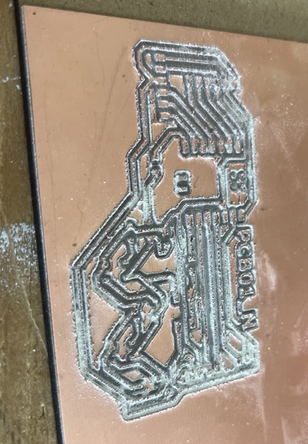
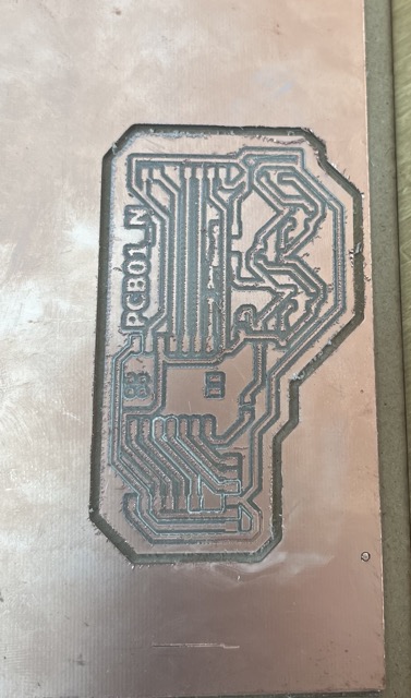
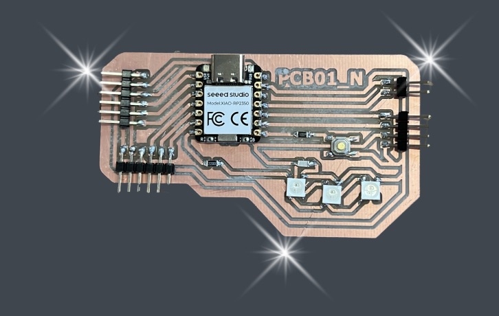
During this week I concluded that the mini mill does not like me. Even though this assignment involved many failed attempts, it helped me understand the complete workflow of electronics production: from exporting the PCB correctly to milling, soldering, and finally programming a functional custom board.
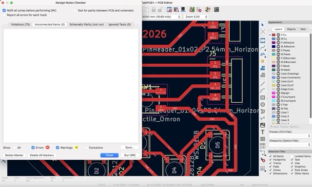
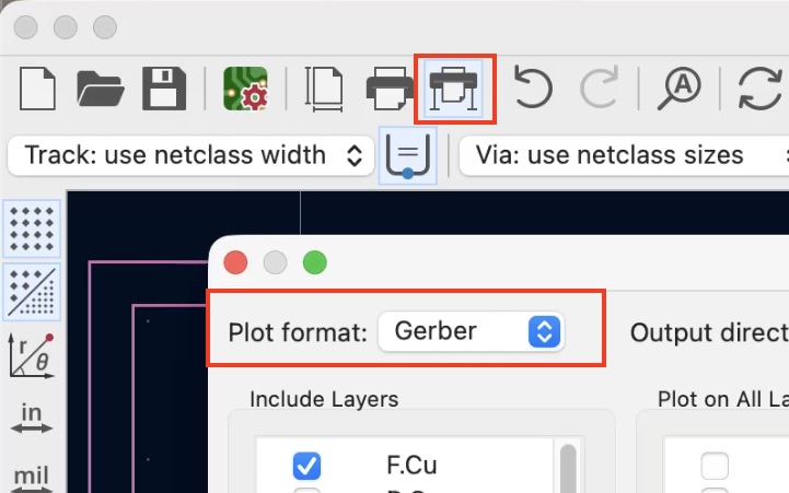
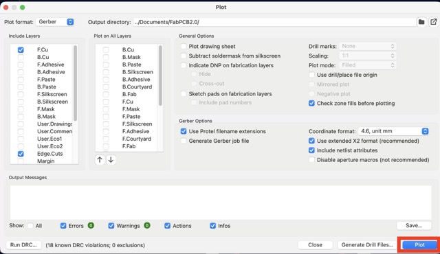
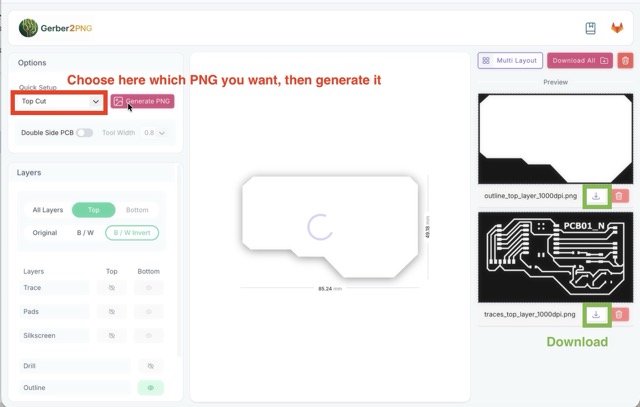
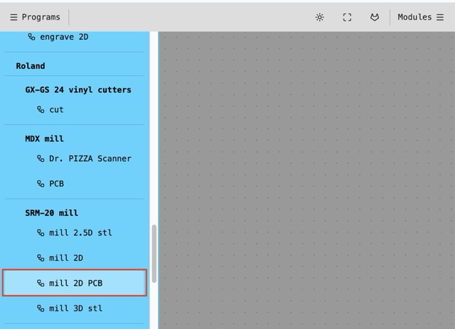
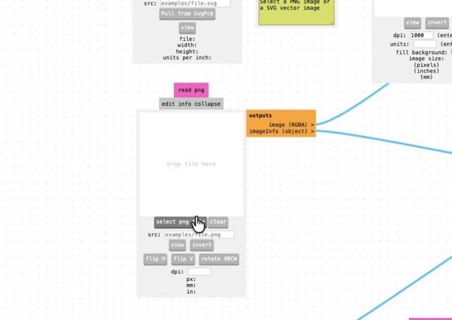
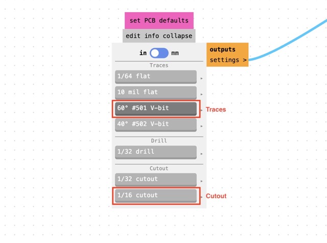
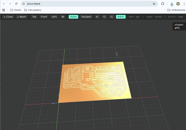
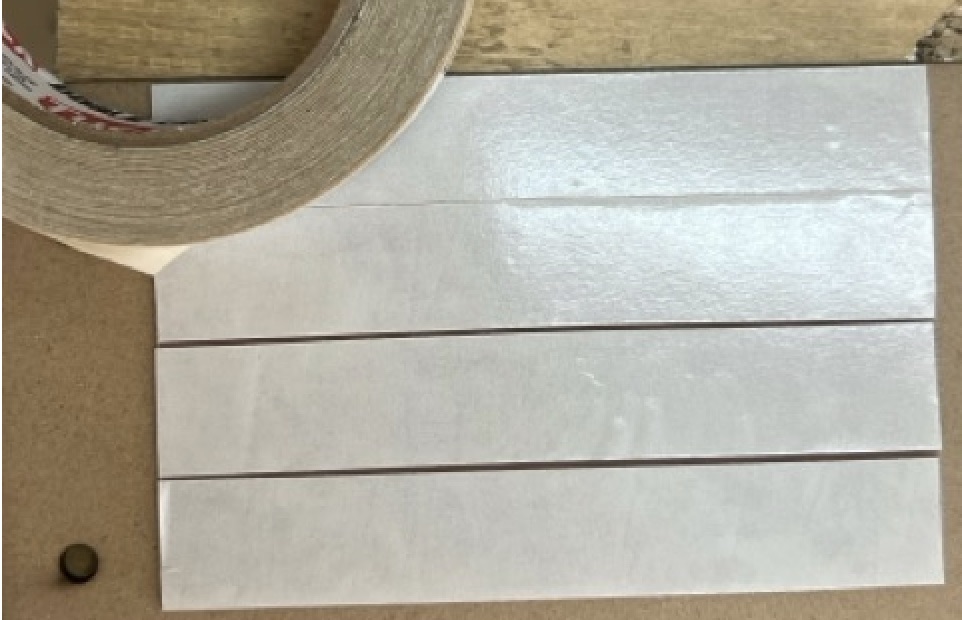
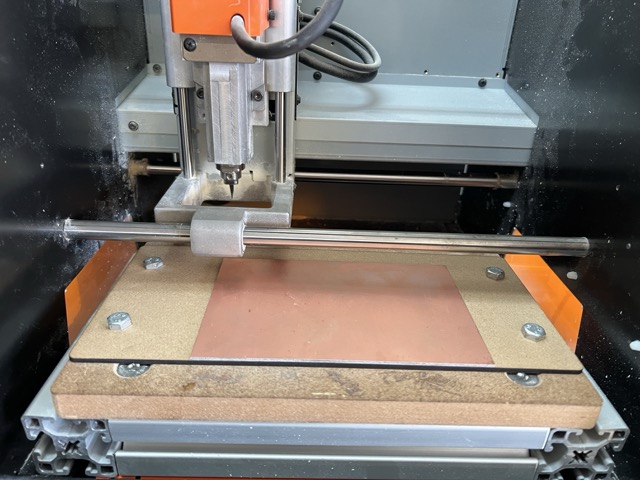
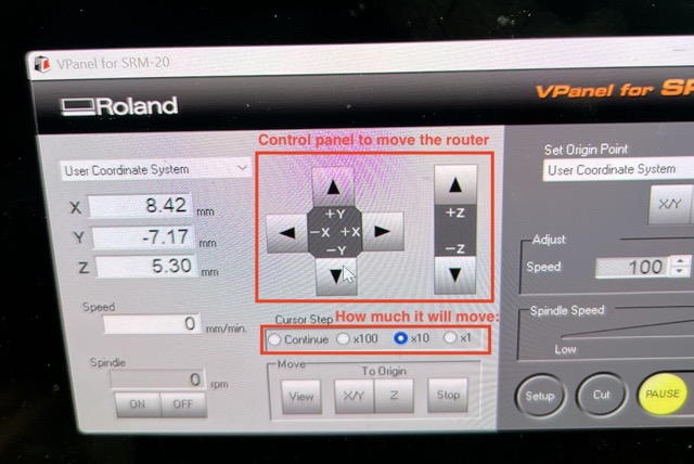
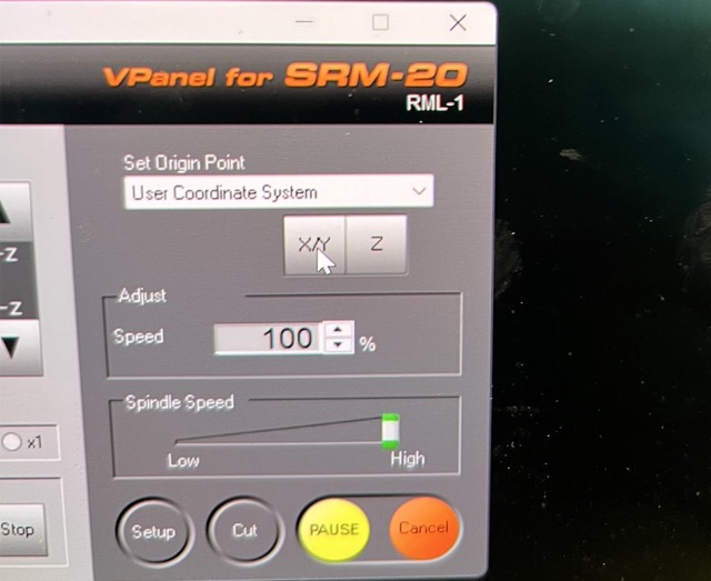
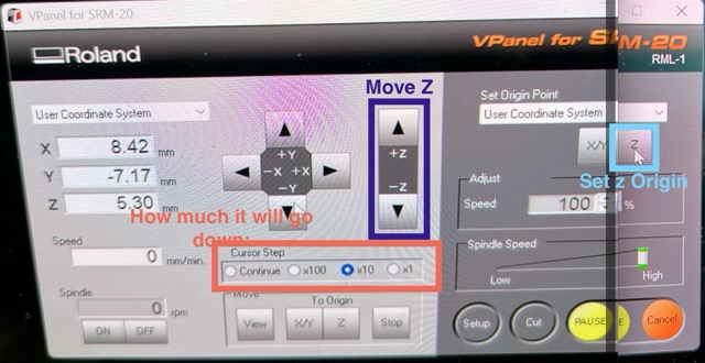
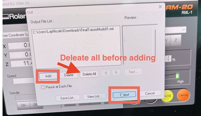
Here is a full guide on how to make your own physical PCB.
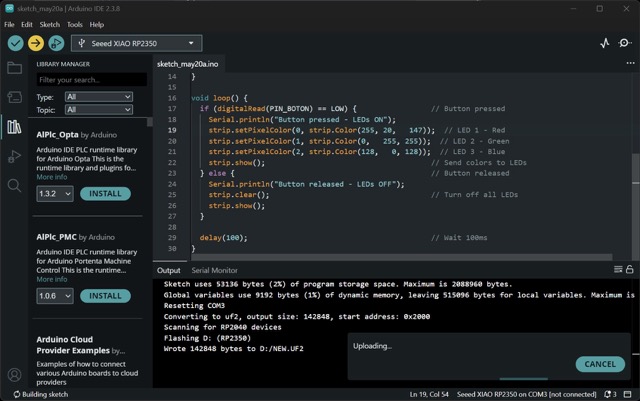
Make and test a microcontroller development board that you designed.

The first part of this week was preparing the digital files so the milling machine could understand my PCB. This meant exporting the board correctly from KiCad and then transforming those files into an RML toolpath using Mods.
Once the digital files were ready, it was time to move to the mini mill. This was the most challenging part of the week because even a very small calibration mistake could ruin the entire PCB.
After finally getting a clean PCB, the next step was assembling all the electronic components by soldering them carefully into place.
Once the board was assembled, the last technical step was programming it to verify that the electronics were actually working.
The first step was to connect the PCB to Arduino IDE, then I wrote some code to test the PCB, in which I turned the LEDs on and off with the button. This entire process is shown in the following carousel, and the code that can be copied is below the carousel.
#include <Adafruit_NeoPixel.h> // NeoPixel library
#define PIN_LEDS D6 // LEDs on pin D6
#define PIN_BOTON D7 // Button on pin D7
#define NUM_LEDS 3 // Number of LEDs
Adafruit_NeoPixel strip(NUM_LEDS, PIN_LEDS, NEO_GRB + NEO_KHZ800);
void setup() {
Serial.begin(115200); // Start serial monitor
pinMode(PIN_BOTON, INPUT_PULLUP); // Button reads HIGH normally, LOW when pressed
strip.begin(); // Start LEDs
strip.setBrightness(30); // Set brightness (0-255)
}
void loop() {
if (digitalRead(PIN_BOTON) == LOW) { // Button pressed
Serial.println("Button pressed - LEDs ON");
strip.setPixelColor(0, strip.Color(255, 20, 147)); // LED 1 - Red
strip.setPixelColor(1, strip.Color(0, 255, 255)); // LED 2 - Green
strip.setPixelColor(2, strip.Color(128, 0, 128)); // LED 3 - Blue
strip.show(); // Send colors to LEDs
} else { // Button released
Serial.println("Button released - LEDs OFF");
strip.clear(); // Turn off all LEDs
strip.show();
}
delay(100); // Wait 100ms
}
After several failed exports, calibration problems, and three milling attempts, I finally obtained a fully working custom development board.
The PCB works as a custom programmable Arduino-like board that connects through USB and can be programmed normally. Seeing the Neopixels finally turn on after so many fabrication issues made the whole process worth it.

