Week 12: Mechanical Design & Machine Design
Week 12 focused on machine design and, unlike previous assignments, this was a group project where multiple systems had to work together as a single machine. The project required coordination between mechanical design, electronics, firmware, fabrication, and user interaction.
To understand the scope of the assignment and what could realistically be achieved within the available time, we began by reviewing documentation from previous Fab Academy machine projects.
Project Concept
During discussions around shared tabletop systems, I was reminded of the rotating Lazy Susan commonly used in Chinese dining settings. The idea evolved from a simple rotating tray into an interactive system that could deliver specific items to specific users.
An automated rotary table that brings selected items to selected users through voice commands using Alexa.
The concept combined mechanical movement, position control, and voice interaction into a single system.
Team Roles
| Area | Team Member |
|---|---|
| Mechanical Design | Abhishek Shah |
| Electronics | Ardradevi |
| Fabrication & Assembly | Ali Abdul Gafoor |
| Firmware | Mishael |
| Alexa Integration | Ashtami P. S. |
Although responsibilities were distributed among team members, very few decisions could be made in isolation. The project was highly interconnected, and progress in one area often depended on decisions made in another.
Mechanical design and electronics were closely linked from the beginning. The positioning system relied on a Hall sensor and magnet, which meant the sensor location, magnet placement, mounting strategy, and alignment tolerances all had to be considered during the mechanical design process. Similarly, the chosen gear ratio directly influenced the step calculations, positioning resolution, and motion planning implemented in firmware.
Mechanical design and fabrication were equally dependent on one another. Features such as gear geometry, motor mounts, bearing placement, clearances, assembly methods, and material selection had to be designed with the available fabrication processes in mind. At the same time, fabrication constraints often required design modifications to ensure parts could be manufactured, assembled, and operated reliably.
Electronics also depended on the mechanical structure. The placement of the Hall sensor, routing of wires, mounting of the stepper motor, PCB positioning, and accessibility for assembly all had to be coordinated with the physical layout of the machine. Small changes in mechanical design could affect sensor alignment and ultimately influence positioning accuracy.
Firmware development depended on all of these decisions. The gear ratio determined the effective step resolution of the system, compartment spacing influenced the lookup table calculations, and the Hall sensor placement affected the homing strategy. Even seemingly simple choices such as the number of user positions or compartment locations changed how positions were mapped and addressed in software.
The Alexa integration added another layer of dependency. Voice commands needed to correspond to physical compartments and user locations, which meant the interaction logic had to align with both the firmware coordinate system and the final mechanical arrangement. A request such as "Bring Cookies to Mishael" only works because the physical layout, lookup table, positioning logic, and communication system all agree on what those locations represent.
As the project evolved, it became clear that the machine was not a collection of separate parts but a system of interconnected decisions. Mechanical design, electronics, fabrication, firmware, and interaction design continuously influenced one another, requiring frequent communication and coordination throughout the development process.
My Contribution
I was responsible for developing the firmware for the rotary table. My work focused on stepper motor control, homing, position tracking, lookup-table based positioning, shortest-path motion planning, and integration with the Alexa workflow.
In addition to firmware development, I coordinated project planning and documentation efforts, and prepared the final presentation slides for the team.
Click here to view the group documentation of Voice Controlled Rotary Table
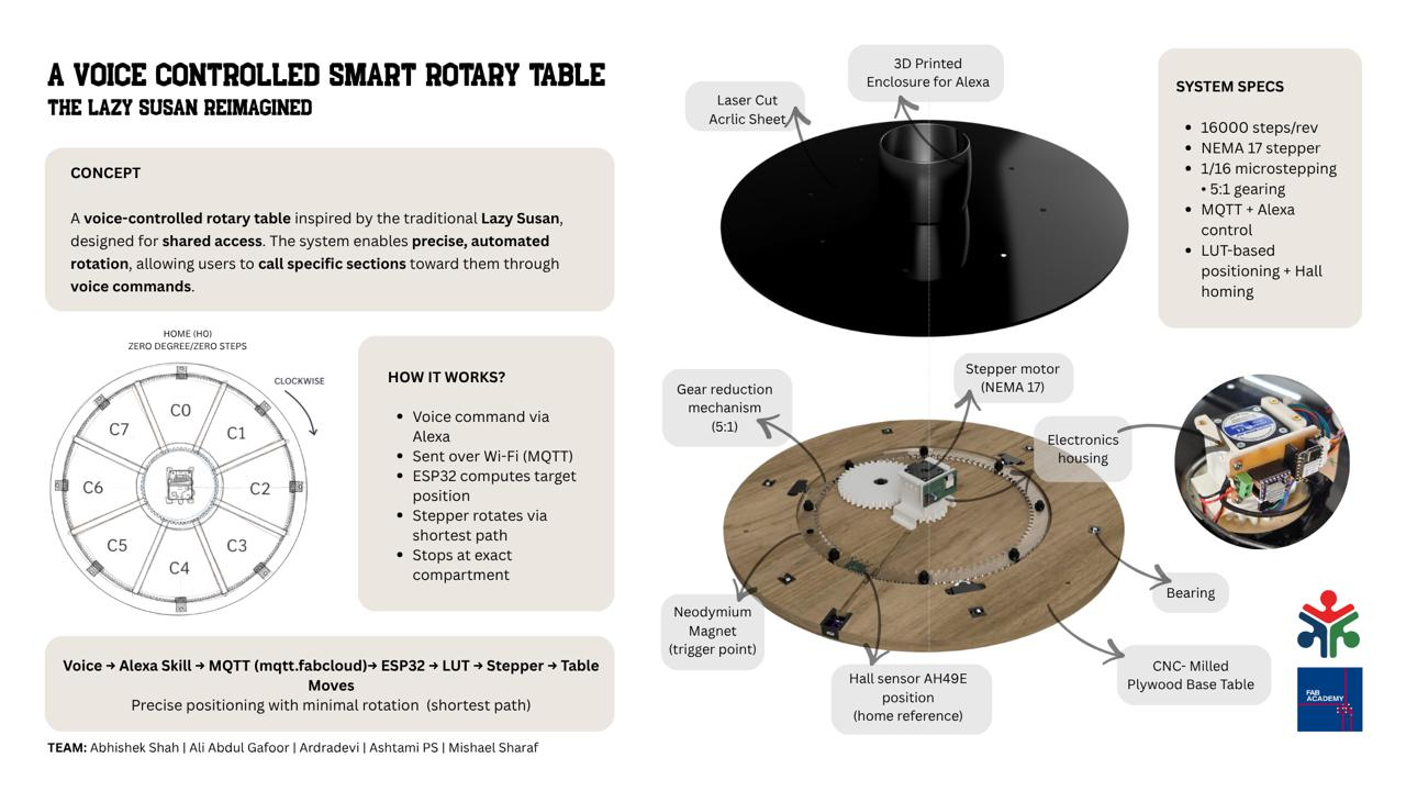
For Machine Week, our team built a voice-controlled rotary table inspired by the traditional Lazy Susan. The idea was simple: instead of manually rotating the table to reach an item, a user could request it through Alexa and have it delivered automatically.
The table is divided into six compartments containing different snacks, while users are assigned fixed positions around the table. When a command is given, Alexa sends the request through MQTT to an ESP32. The firmware then determines the required destination using a lookup table, calculates the shortest path to get there, and rotates the table using a stepper motor.
To make positioning reliable, the system establishes a reference position every time it starts. A Hall effect sensor and magnet are used to perform a homing sequence, allowing the firmware to define a known zero position before any movement takes place.
The project brought together mechanical design, electronics, fabrication, firmware, and voice interaction into a single system. While we demonstrated it using snacks and users around a table, the same approach could be applied to organizing tools, materials, or shared resources in other environments.
At its core, the project explores how a simple rotary mechanism can become a more interactive and intelligent system when combined with sensing, positioning, and automation.
Collaborative Workspace Setup and Project Management
Our instructors, Jogin and Saheen helped us set up a collaborative workspace on Miro and guided us on project management tools. Later, all members contributed their research and work updates to this space and it was easier for us to keep track and refer details.
I was in charge of project management using Gantt Chart
System Definition
The system was defined as:
- Circular table (~55 cm diameter)
- 6 compartments (60° separation)
- Multiple fixed user positions (homes)
- Central stepper-driven mechanism
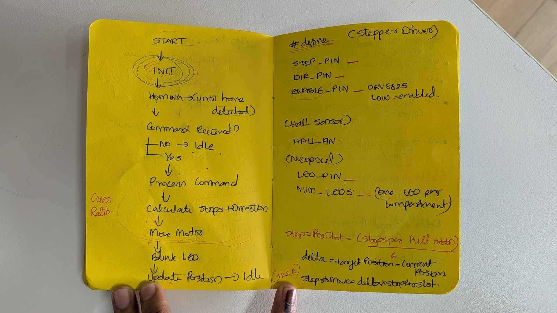
Design Thinking Before Implementation
A significant portion of my time was spent imagining system behavior before testing.
Key Questions
- How will a user call a compartment?
- Should the table always rotate in one direction?
- Or should it choose the shortest path?
- What kind of motion feels natural to a user?
- How do we ensure repeatability every time?
This early reasoning helped identify core issues before hardware testing:
- Direction ambiguity (CW vs CCW)
- Position drift over time
- Need for a consistent reference
Hardware Overview: Stepper Motor Fundamentals
What is a Stepper Motor?
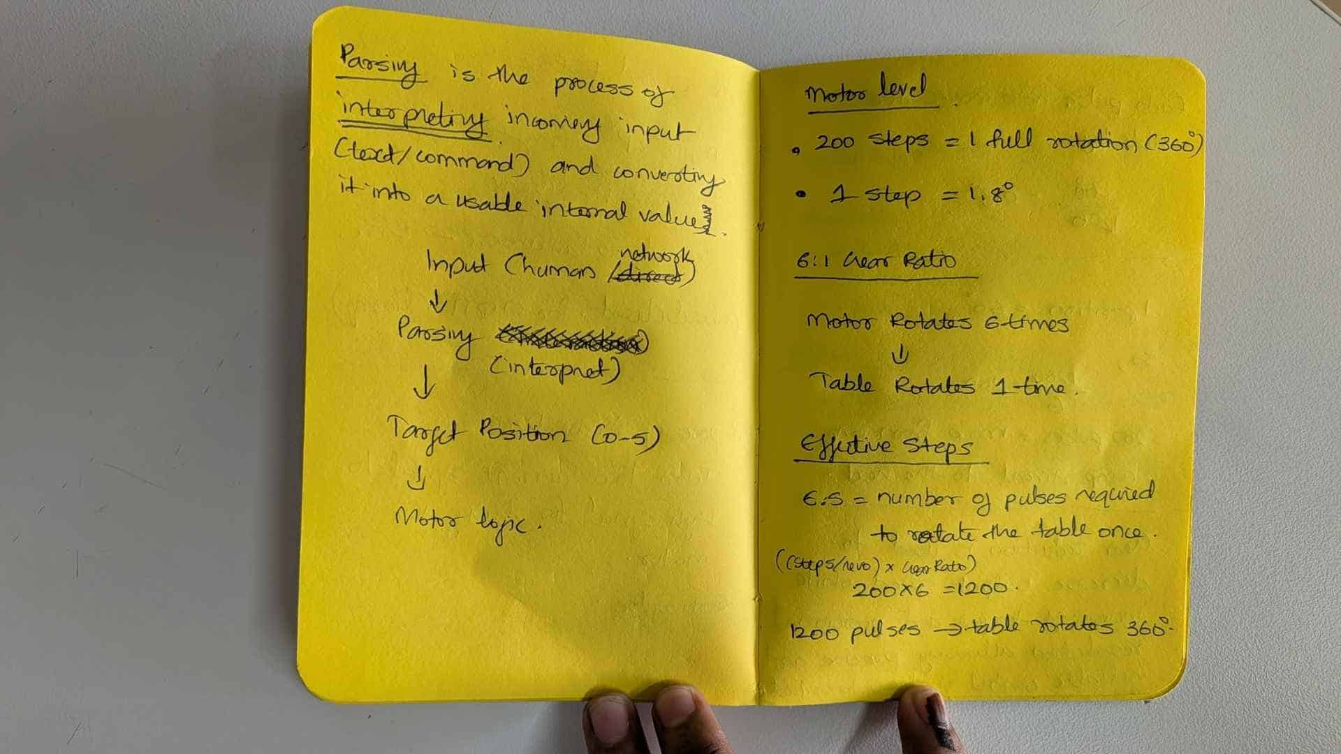
A stepper motor rotates in discrete angular steps, enabling precise position control.
Typical NEMA 17
- 200 steps per revolution
- 1 step = 1.8°
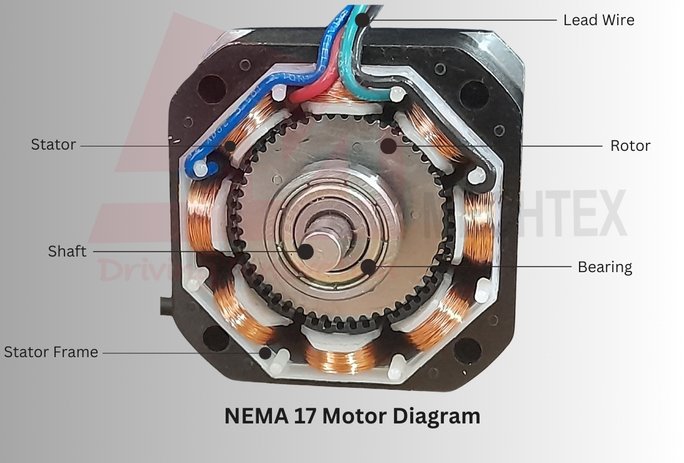
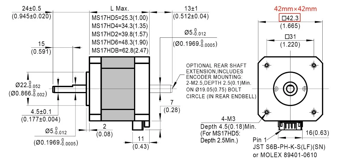
Image source: Mechtex, MOONS Industries
Bipolar Stepper (Used in this System)
- Contains two coils (phases)
- Driver reverses current direction
- Magnetic field rotates and the rotor aligns step-by-step
Why a Driver is Required
Microcontrollers cannot directly drive motors. The DRV8825 stepper motor driver:
- Supplies the required current
- Converts STEP and DIR signals into coil switching
- Protects the microcontroller
Control Signals
| Signal | Function |
|---|---|
| STEP | Each pulse = one step |
| DIR | Controls direction |
| ENABLE | Enables/disables motor |
Hall Sensor – AH49E
- Analog Hall effect sensor
- Used for detecting magnetic reference
Processing Approach
- Low-pass filtering → remove noise
- Threshold detection → identify magnet presence
- Hysteresis → prevent output flicker near threshold
From Geometry to Step Counts
Before writing any motion code, I first needed a way to describe positions around the table.
The table was designed with six compartments spaced equally around the circumference. At the same time, users would be seated at fixed positions around the table. The challenge was not simply rotating the motor, but determining exactly how many motor steps were required to align any compartment with any user position.
I began by treating the system as a circular coordinate problem.
- One full rotation = 360°
- 6 compartments = 60° spacing
- Homes (user positions) are fixed angular locations around the table
- The table rotates while the homes remain stationary
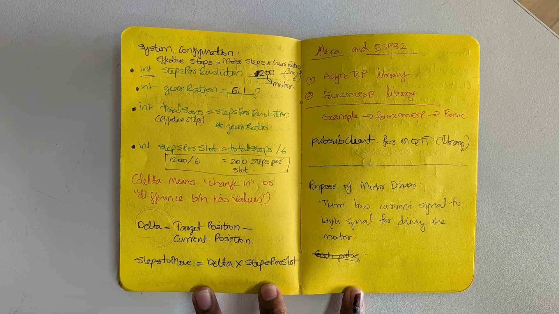
To convert these angular positions into motor movement, I first calculated the effective step resolution of the system.
Step Resolution
Motor Resolution      = 200 steps/rev
Microstepping         = 1/16
Gear Ratio            = 5:1

Effective Resolution
= 200 × 16 × 5
= 16000 steps per table revolution
This means the table requires 16,000 microsteps to complete one full rotation.
Steps per Degree
16000 / 360
≈ 44.44 steps per degree
Using this value, any angular position on the table could be converted into a step position.
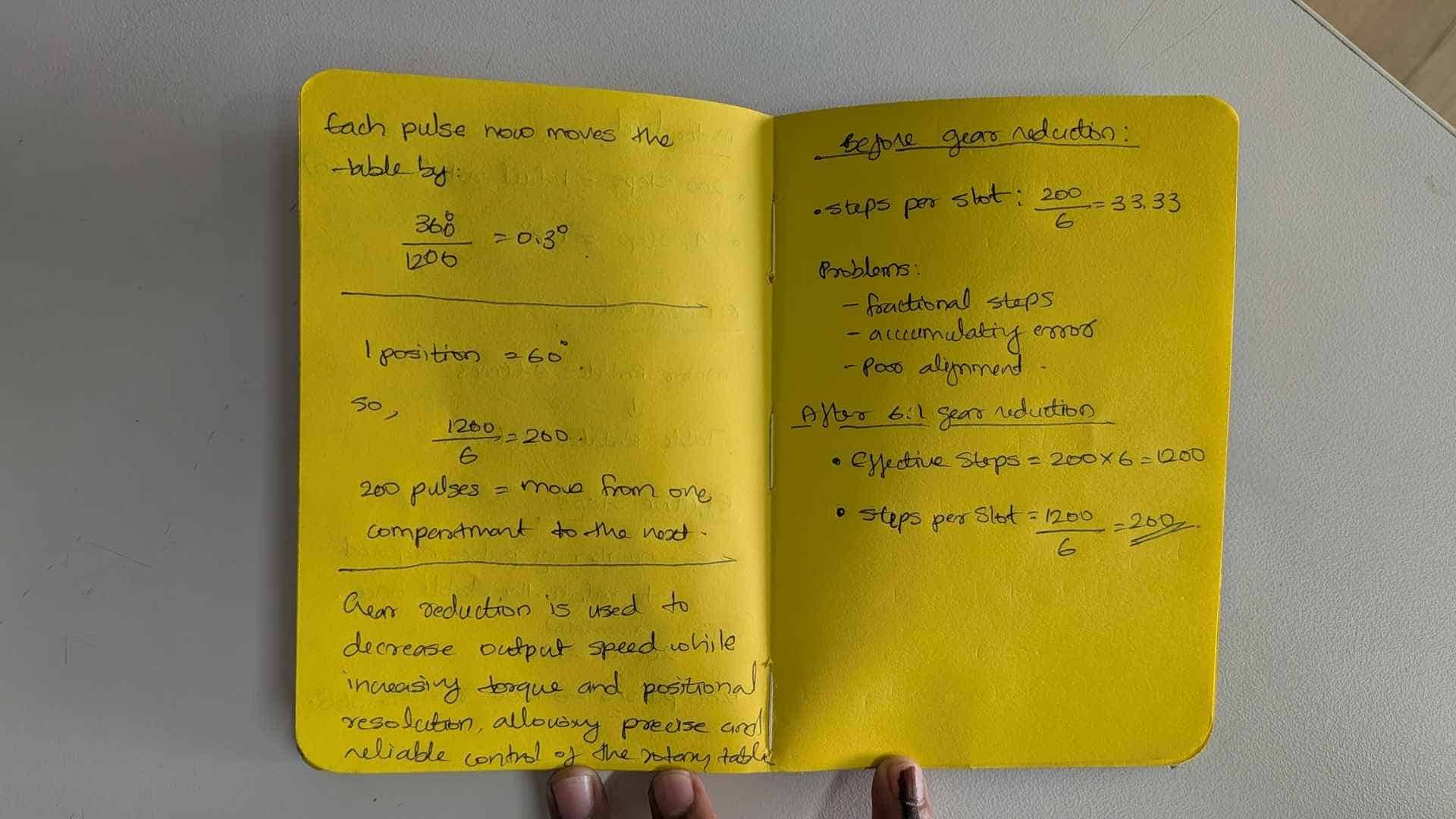
Compartment Spacing
Since the six compartments are separated by 60°:
60 × 44.44
≈ 2666.67 steps
At first glance this seems straightforward. However, stepper motors can only move in whole-number steps.
The value 2666.67 cannot be executed directly and must be rounded.
This created an important problem.
The Rounding Error Problem
If every movement was calculated relative to the previous compartment, the system would repeatedly round 2666.67 to a nearby integer value.
For example:
C1 → C2 = 2665
C2 → C3 = 2665
C3 → C4 = 2665
...
Each movement introduces a small error.
Individually the error is tiny, but after many rotations those errors accumulate, causing the table to drift away from its intended alignment.
This meant that relative positioning was not reliable enough for repeated operation.
The solution was to stop thinking about movement and start thinking about addresses.
Instead of asking:
How far should I move from where I am?
I started asking:
Where should this compartment be located in the global coordinate system?
This led to the use of absolute positioning and eventually the lookup table.
From Compartments and People to Step Addresses
Once the mechanical system was working, the next challenge was determining how many motor steps were required to bring any compartment in front of any user.
I started by thinking about the table as two independent coordinate systems:
- Homes (H1–H4) → fixed user positions around the table
- Compartments (C1–C6) → positions attached to the rotating table
The homes never move. The compartments rotate with the table.
Step Resolution
The final motion resolution of the table was calculated from the motor, microstepping configuration, and gear reduction.
Motor Resolution = 200 steps/revolution

Microstepping = 1/16

Gear Ratio = 5:1

Total Table Resolution

= 200 × 16 × 5

= 16000 steps/revolution
This means one complete rotation of the table corresponds to 16,000 microsteps.
Therefore:
1° ≈ 16000 / 360

≈ 44.44 steps
Defining the Homes
The first positions I defined were the homes. These represent fixed user locations around the table.
| Home | Angle | Step Address |
|---|---|---|
| H1 | 0° | 0 |
| H2 | 90° | 4000 |
| H3 | 180° | 8000 |
| H4 | 270° | 12000 |
These values remain constant because the users do not move.
Two Different Coordinate Systems
At first glance it might seem unusual that the system contains six compartments but only four homes. This is because the two represent different things.
- Compartments (C1–C6) are physical storage locations attached to the rotating table.
- Homes (H1–H4) are fixed user positions around the table.
The compartments rotate with the table, while the homes remain stationary.
During the initial design phase, the system was intended to serve four users seated around the table at approximately 90° intervals.
| Element | Quantity | Description |
|---|---|---|
| Compartments | 6 | Storage locations on the rotating table |
| Homes | 4 | Fixed user positions around the table |
This means the controller must support every possible combination of compartment and user position.
6 Compartments × 4 Homes

= 24 Possible Alignments
Each of these alignments corresponds to a unique destination in the lookup table.
Defining the Compartments
The table contains six equally spaced compartments.
360° / 6

= 60° between compartments
Converting this angular spacing into steps gives:
60 × 44.44

≈ 2666.67 steps
Since the motor can only move in whole-number steps, the values were rounded and assigned as compartment offsets.
| Compartment | Angle | Offset |
|---|---|---|
| C1 | 0° | 0 |
| C2 | 60° | 2665 |
| C3 | 120° | 5332 |
| C4 | 180° | 7999 |
| C5 | 240° | 10666 |
| C6 | 300° | 13333 |
These values represent the angular relationship between compartments, not actual motor movements.
The Key Question
At this point I had:
- Fixed home addresses
- Fixed compartment offsets
The remaining question was:
What absolute table position places a selected compartment in front of a selected user?
For example:
C2 → H2

Compartment Offset = 2665

Home Offset = 4000

Final Position = 2665 + 4000

= 6665
This means that when the table reaches step position 6665, compartment C2 will be aligned with Home H2.
Wrap-Around Behaviour
Some combinations exceed one complete revolution.
For example:
C5 → H3

10666 + 8000

= 18666
Since the table only contains positions from 0 to 15999, the value must wrap around.
18666 % 16000

= 2666
This keeps every valid position inside a single revolution.
Building the Lookup Table
The lookup table contains every valid alignment between a compartment and a home.
Each row represents a compartment attached to the rotating table.
Each column represents a fixed home position.
Since there are six compartments and four homes, the table contains:
6 × 4 = 24 possible states
Each cell stores the absolute step address required to align that compartment with that home.
The Formula Behind the Lookup Table
After calculating several combinations, a pattern became obvious.
Position

=

(Compartment Offset + Home Offset)

% 16000
This single equation generates every destination in the system.
Rather than calculating these values repeatedly during operation, I precomputed them and stored them in a lookup table.
Why a Lookup Table?
The lookup table does not store movements.
It stores destinations.
Each cell answers a single question:
At what absolute step position should the table be located so that a specific compartment aligns with a specific home?
This approach simplified the firmware, eliminated repeated calculations, and provided a fixed set of repeatable target positions for the motion controller.
Visualizing the Lookup Table
Using the relationship:
Position = (Compartment Offset + Home Offset) % 16000
I generated a table containing every valid destination in the system.
Rows represent compartments attached to the rotating table, while columns represent fixed user positions around the table.
| H1 0 |
H2 4000 |
H3 8000 |
H4 12000 |
|
|---|---|---|---|---|
| C1 0 |
0 | 4000 | 8000 | 12000 |
| C2 2665 |
2665 | 6665 | 10665 | 14665 |
| C3 5332 |
5332 | 9332 | 13332 | 1332 |
| C4 7999 |
7999 | 11999 | 15999 | 3999 |
| C5 10666 |
10666 | 14666 | 2666 | 6666 |
| C6 13333 |
13333 | 1333 | 5333 | 9333 |
Each value represents an absolute step address within a single revolution (0–15999).
For example:
- 6665 means "place compartment C2 in front of H2"
- 1332 means "place compartment C3 in front of H4"
- 2666 means "place compartment C5 in front of H3"
Rather than storing how far the motor should move, the table stores where the system should end up.
This distinction became important later when implementing shortest-path motion planning and homing-based absolute positioning.
Moving horizontally across a row adds 4000 steps each time because the homes are separated by 90°. Moving vertically down a column adds approximately 2666 steps because the compartments are separated by 60°. The values that suddenly become small again (1332, 2666, 3999, etc.) are positions that wrapped around after exceeding 16000 steps.
                 Homes
            H1   H2   H3   H4
          ---------------------
C1  --->    •    •    •    •
C2  --->    •    •    •    •
C3  --->    •    •    •    •
C4  --->    •    •    •    •
C5  --->    •    •    •    •
C6  --->    •    •    •    •

24 valid alignments
Motion Control Fundamentals
Motion Logic Evolution
Once absolute target positions were established using the lookup table, the next challenge was deciding how the table should move between positions.
The question was no longer:
Where should the table go?
Instead, it became:
What is the best path to get there?
Stage 1: Clockwise-Only Motion
The first implementation used a simple clockwise-only strategy.
delta = target - current

if (delta < 0)
    delta += 16000
If the target position was behind the current position, the system wrapped around and continued moving clockwise until it reached the destination.
For example:
Current = 14000
Target  = 2000

delta = 2000 - 14000

delta = -12000

delta += 16000

delta = 4000
The table therefore rotates 4000 steps clockwise.
- Simple to implement
- Easy to debug
- Useful during early testing
- Avoided direction changes
However, this approach was often inefficient.
A destination that was only a short distance behind the current position could require almost a full revolution to reach.
Stage 2: Shortest Path Motion
After validating the positioning system, I changed the motion planner to choose the shortest rotational path.
delta = target - current

if (delta > 8000)
    delta -= 16000

if (delta < -8000)
    delta += 16000
The logic is based on the fact that:
Full Revolution = 16000 steps

Half Revolution = 8000 steps
Any movement greater than half a revolution is no longer the shortest route.
In those cases, the controller reverses direction and approaches the target from the opposite side.
Example 1
Current = 2000
Target  = 14000

delta = 12000
Moving 12000 steps clockwise would reach the target, but this is longer than half a revolution.
The controller therefore converts the movement:
delta = 12000 - 16000

delta = -4000
The motor moves 4000 steps counter-clockwise instead of 12000 steps clockwise.
Example 2
Current = 12000
Target  = 14000

delta = 2000
Since the movement is already less than half a revolution, no correction is required.
The motor simply moves 2000 steps clockwise.
Visual Interpretation
The shortest-path algorithm treats the turntable as a circular coordinate system.
Any destination can be reached in two directions:
- Clockwise (CW)
- Counter-clockwise (CCW)
The controller compares both possibilities and selects whichever requires fewer steps.
This reduces travel distance, improves response time, and creates motion that feels more natural to the user.
Design Outcome
The final system combines:
- Absolute positioning using the lookup table
- Homing-based reference calibration
- Shortest-path motion planning
The lookup table determines where the table should go.
The shortest-path algorithm determines how it should get there.
Final Mapping After Alexa Integration
During early development, the system used generic labels such as C1–C6 and H1–H4 to simplify testing and motion control.
Once Alexa integration was introduced, the command structure became user-facing. Generic labels were no longer meaningful, so the homes and compartments were mapped to real people and real items.
This allowed commands to be interpreted in a more natural way.
For example:
"Bring Cookies to Mishael"
instead of:
"C6 → H5"
Homes → People
| Home | Person |
|---|---|
| H1 | Abhishek |
| H2 | Ardra |
| H3 | Ali |
| H4 | Ashtami |
| H5 | Mishael |
Compartments → Items
| Compartment | Item |
|---|---|
| C1 | Nachos |
| C2 | Juice |
| C3 | Lays |
| C4 | Snickers |
| C5 | Popcorn |
| C6 | Cookies |
Expanding from 4 Homes to 5 Homes
The original system assumed four user positions spaced 90° apart.
After the complete team was included in the Alexa workflow, a fifth home position was added.
This changed the angular spacing between homes:
360° / 5

= 72°
Using the table resolution of 16000 steps per revolution:
16000 / 5

= 3200 steps
Therefore each home is separated by 3200 steps.
Home Offsets
| Home | Angle | Step Offset |
|---|---|---|
| H1 | 0° | 0 |
| H2 | 72° | 3200 |
| H3 | 144° | 6400 |
| H4 | 216° | 9600 |
| H5 | 288° | 12800 |
Updated Lookup Table
The same lookup-table logic was retained.
Only the home offsets changed.
Each cell still represents the absolute position required to align a selected compartment with a selected user.
| Item | Abhishek | Ardra | Ali | Ashtami | Mishael |
|---|---|---|---|---|---|
| Nachos | 0 | 3200 | 6400 | 9600 | 12800 |
| Juice | 2667 | 5867 | 9067 | 12267 | 15467 |
| Lays | 5333 | 8533 | 11733 | 14933 | 2133 |
| Snickers | 8000 | 11200 | 14400 | 1600 | 4800 |
| Popcorn | 10667 | 13867 | 1067 | 4267 | 7467 |
| Cookies | 13333 | 533 | 3733 | 6933 | 10133 |
The resulting lookup table contains:
6 Compartments × 5 Homes

= 30 possible alignments
Each alignment corresponds to a unique absolute step address that can be recalled directly by the controller.
Firmware Architecture
The final firmware combines several independent subsystems that work together to achieve reliable positioning.
| Module | Purpose |
|---|---|
| Stepper Control | Generates motor motion using the DRV8825 driver and AccelStepper library. |
| Hall Sensor Processing | Converts noisy analog Hall sensor readings into a stable digital signal. |
| Homing System | Establishes a repeatable reference position during startup. |
| Lookup Table (LUT) | Stores all valid compartment-home alignments as absolute step positions. |
| Motion Planner | Calculates the shortest route to a target position. |
| Position Tracking | Maintains the current absolute position of the turntable. |
| MQTT / Alexa Interface | Receives user commands and converts them into motion requests. |
The following sections explain the most important parts of the firmware in detail.
Homing Logic
The positioning system relies on absolute step addresses stored in the lookup table. For these addresses to have meaning, the controller must first establish a known physical reference.
This is the purpose of the homing sequence.
During homing, a Hall effect sensor detects a magnet mounted on the turntable. The detected position becomes the system's zero reference.
After homing:
Current Position = 0

C1 aligned with H1
Every subsequent movement is calculated relative to this reference.
Why Not Stop on First Detection?
A Hall sensor does not detect a single point. Instead, it detects a magnetic field over a small region.
If the motor stopped immediately on first detection, the final position would vary slightly depending on speed, inertia, and sensor response.
To improve repeatability, a multi-stage homing sequence was implemented.
Homing State Machine
SEARCH
   ↓
BACKOFF
   ↓
APPROACH
   ↓
DONE
SEARCH
The motor rotates clockwise at a relatively high speed until the Hall sensor first detects the magnet.
SEARCH_SPEED = 800
This stage prioritizes speed over precision.
BACKOFF
Once the magnet is detected, the motor reverses direction and moves away until the magnetic field is completely cleared.
This ensures the system starts the final approach from outside the detection zone.
APPROACH
The motor then approaches the magnet again at a much slower speed.
APPROACH_SPEED = 200
The second detection event occurs under controlled conditions and provides a significantly more repeatable reference point.
DONE
When the magnet is detected during the slow approach:
stepper.setCurrentPosition(0);
The controller assigns:
Position = 0
From this point onward, every lookup-table address corresponds to a known physical location on the turntable.
Result
The homing procedure transforms an unknown startup position into a repeatable global reference frame.
Without homing, the lookup table, shortest-path calculations, and absolute positioning system would all become invalid.
Firmware Implementation
The final firmware can be understood as four cooperating subsystems:
- Hall Sensor Processing
- Homing State Machine
- Motion Planner
- System State Machine
Each subsystem solves a different problem and builds upon the previous one.
1. Hall Sensor Processing
The AH49E Hall sensor provides an analog signal that changes when a magnet passes nearby.
Raw readings contain noise and small fluctuations, making direct detection unreliable.
Low-Pass Filtering
filtered = 0.8f * filtered + 0.2f * raw;
This acts as a simple low-pass filter.
- Reduces noise
- Smooths sudden spikes
- Produces a more stable signal
Hysteresis
if (!hallState && filtered > ON_THRESHOLD)
    hallState = true;

if (hallState && filtered < OFF_THRESHOLD)
    hallState = false;
Two different thresholds are used.
- ON_THRESHOLD → enter magnet zone
- OFF_THRESHOLD → leave magnet zone
This prevents rapid switching when the signal hovers near a threshold.
2. Homing State Machine
Once reliable magnet detection was available, it could be used to establish a physical reference.
Because the turntable uses absolute positioning, the controller must first determine where position zero is located.
State Diagram
SEARCH
  ↓
BACKOFF
  ↓
APPROACH
  ↓
DONE
Implementation
switch (state) {

case SEARCH:
  ...
  break;

case BACKOFF:
  ...
  break;

case APPROACH:
  ...
  break;
}
SEARCH
- Fast clockwise rotation
- Find magnet region quickly
- Detect rising edge
if (currentHall && !lastHall)
The sensor has just entered the magnetic field.
BACKOFF
- Reverse direction
- Move completely outside the magnet zone
- Detect falling edge
if (!currentHall && lastHall)
The sensor has fully exited the magnetic field.
APPROACH
- Slow clockwise motion
- Perform precise edge detection
- Establish final reference position
stepper.setCurrentPosition(0);
This defines the global coordinate origin used by the lookup table.
After homing:
Position 0

C1 aligned with H1
3. Motion Planning
Once a target position is selected from the lookup table, the controller must decide how to reach it.
Lookup Table Selection
long target = LUT[c][h];
This converts:
Compartment + Home

↓

Absolute Step Address
No geometric calculations are required during operation.
Shortest Path Calculation
delta = target - turntableStepPos;
This calculates the distance between the current position and the target.
The movement is then normalized to the shortest rotational path.
if (delta > 8000)
    delta -= 16000;

if (delta < -8000)
    delta += 16000;
Because:
Full Revolution = 16000

Half Revolution = 8000
Any movement larger than half a revolution is replaced with the shorter path in the opposite direction.
Movement Execution
stepper.moveTo(
  stepper.currentPosition() + delta
);
The lookup table provides the destination.
The shortest-path planner determines the route.
4. System State Machine
The overall firmware is controlled using a higher-level state machine.
HOMING
  ↓
IDLE
  ↓
POSITIONING
  ↓
IDLE
HOMING
- Runs homing routine
- Establishes reference position
IDLE
- Waits for commands
- Accepts Serial and MQTT requests
POSITIONING
- Executes motion command
- Monitors movement completion
if (stepper.distanceToGo() != 0)
The motor continues moving until the target is reached.
Final Refinement: Crawl Speed
if (abs(stepper.distanceToGo()) < CRAWL_THRESHOLD)
{
  stepper.setMaxSpeed(CRAWL_SPEED);
}
As the target approaches, the motor automatically slows down.
- Improves stopping accuracy
- Reduces overshoot
- Produces smoother motion
Complete System Flow
Power On

↓

HOMING

↓

Position = 0

↓

Wait for Command

↓

Lookup Table

↓

Shortest Path

↓

Motor Motion

↓

IDLE
This sequence allows a user command to be translated into a repeatable physical position on the turntable.
Firmware Overview
Intent
The goal of the firmware was to transform a stepper motor-driven turntable into a system capable of delivering a selected compartment to a selected user.
To achieve this, the system needed to know its position, establish a repeatable reference at startup, interpret user requests, and move efficiently between destinations.
Rather than treating the turntable as a motor that rotates by a certain number of steps, the firmware treats it as a circular coordinate system where every compartment-home combination corresponds to a predefined address.
Requirements
| ID | Requirement |
|---|---|
| R1 | Establish a repeatable reference position at startup. |
| R2 | Track the turntable position within a full revolution. |
| R3 | Move any compartment to any user position. |
| R4 | Minimize travel distance during movement. |
| R5 | Accept commands from Serial and Alexa/MQTT. |
| R6 | Maintain repeatable positioning over repeated movements. |
How Each Requirement Was Addressed
| Requirement | Implementation |
|---|---|
| R1 | Hall sensor, magnet, filtering, hysteresis, and a homing state machine. |
| R2 | Absolute position tracking using a 0–15999 step coordinate system. |
| R3 | Lookup table containing all valid compartment-home alignments. |
| R4 | Shortest-path motion planning using circular distance calculations. |
| R5 | Serial command parser and MQTT subscriber. |
| R6 | Absolute positioning and repeatable homing strategy. |
Firmware Architecture
The firmware is organized into four major subsystems.
| Subsystem | Purpose |
|---|---|
| Hall Sensor Processing | Converts noisy analog readings into reliable digital events. |
| Homing System | Establishes a repeatable reference position. |
| Motion Planner | Determines where to move and how to get there. |
| Communication Interface | Receives commands from Serial and MQTT. |
High-Level Firmware Flow
Power On

↓

Initialize Hardware

↓

Homing

↓

Position = 0

↓

Wait for Command

↓

Lookup Table

↓

Shortest Path Calculation

↓

Move Motor

↓

Target Reached

↓

Wait for Command
System Architecture
User Command
(Serial / Alexa)

        ↓

Command Parser

        ↓

Lookup Table

        ↓

Motion Planner

        ↓

Stepper Motor

        ↓

Turntable Motion

        ↑

Hall Sensor
(Homing Reference)
The Hall sensor establishes the reference position, the lookup table determines the destination, and the motion planner determines the shortest route between them.
Development Process
The firmware was developed in parallel with the mechanical design. Since the physical system was not immediately available, a significant amount of time was spent modelling the behaviour of the turntable before full integration.
Rather than starting with a complete system, each subsystem was developed and validated independently.
Key Areas of Investigation
- Stepper motor behaviour and positioning accuracy
- Microstepping and effective system resolution
- Coordinate mapping between compartments and users
- Homing strategies using a Hall effect sensor
- Motion planning and shortest-path selection
- Failure cases such as positional drift and cumulative rounding errors
This process ultimately led to the adoption of absolute positioning and lookup-table based control.
Incremental Testing Strategy
To simplify debugging, the system was developed in stages.
| Stage | Objective |
|---|---|
| 1 | Verify basic stepper motion and direction control |
| 2 | Configure microstepping and confirm system resolution |
| 3 | Read and characterize Hall sensor behaviour |
| 4 | Implement and validate homing |
| 5 | Test absolute positioning using predefined targets |
| 6 | Implement shortest-path motion planning |
| 7 | Integrate MQTT communication and Alexa commands |
| 8 | Validate complete end-to-end operation |
Each stage was tested independently before moving to the next, making it easier to isolate and troubleshoot problems.
Key Firmware Structures
The final firmware is built around a small number of core structures.
| Component | Purpose |
|---|---|
| System Constants | Define mechanical resolution, speeds and operating limits. |
| Lookup Table (LUT) | Stores all valid compartment-home alignments. |
| Hall Sensor Processing | Provides stable magnetic detection using filtering and hysteresis. |
| Homing FSM | Establishes a repeatable reference position. |
| Motion Planner | Selects the shortest path to a target. |
| System FSM | Coordinates homing, positioning and idle operation. |
Final Firmware Flow
Power On

↓

Hall Sensor Active

↓

Homing Sequence

↓

Position = 0

↓

Wait for Command

↓

Lookup Table Lookup

↓

Shortest Path Calculation

↓

Motor Motion

↓

Target Reached

↓

Idle
The result is a repeatable positioning system in which every user request is translated into a predefined absolute destination and executed through the shortest available route.
Test 1: Hall Effect Sensor Magnet Detection
Before implementing homing, I needed to verify that the AH49E Hall effect sensor could reliably detect the magnet mounted on the turntable.
The goal of this test was to determine whether the sensor output changed consistently when a magnet approached and moved away.
Reference: AH49E Hall Effect Sensor Datasheet
https://www.diodes.com/assets/Datasheets/AH49E.pdf
Test Objective
- Read the analog Hall sensor output
- Detect the presence of a magnet
- Avoid repeated triggering while the magnet remained nearby
- Reset detection once the magnet was removed
Code
#define HALL_PIN D8

bool magnetDetected = false;

void setup() {
Serial.begin(115200);
}

void loop() {

int val = analogRead(HALL_PIN);

// Detect magnet (only when it first appears)
if (!magnetDetected && val > 3800) {
magnetDetected = true;
Serial.println("MAGNET CLOSE");
}

// Reset state when magnet is removed
if (magnetDetected && val < 3400) {
magnetDetected = false;
}

delay(20);
}
How It Works
analogRead()continuously reads the Hall sensor output.- If the reading rises above
3800, the system assumes a magnet has entered the detection zone. - The boolean flag prevents repeated printing while the magnet remains nearby.
- Once the reading drops below
3400, the flag resets and the sensor becomes ready for the next detection event.
Using separate ON and OFF thresholds introduces a simple form of hysteresis, preventing rapid toggling near the detection boundary.
Result
When the magnet was brought close to the sensor, the Serial Monitor printed:
MAGNET CLOSE
The message was printed only once per approach and did not continuously repeat while the magnet remained in place.
Outcome
- Confirmed the AH49E sensor could reliably detect the magnet.
- Established preliminary threshold values for magnet detection.
- Provided the foundation for the homing routine developed later.
Test 2: Converting the Hall Sensor into a Reliable Digital Switch
The previous test confirmed that the AH49E Hall effect sensor could detect a nearby magnet. However, the raw analog readings were noisy and unsuitable for direct use in the homing algorithm.
Since the final system only needed to know whether the magnet was present or not, the next step was to convert the analog sensor into a stable digital signal.
This required three improvements:
- Threshold detection
- Hysteresis
- Signal filtering
Problem Observed
While monitoring the raw analog values, occasional spikes and fluctuations appeared even when the magnet position remained unchanged.
Without additional processing, these fluctuations could cause false triggering and unstable homing behaviour.
Solution
The sensor reading was processed in three stages:
- Apply a low-pass filter to smooth the signal.
- Use separate ON and OFF thresholds.
- Trigger events only when the state changes.
Code
#define HALL_PIN D8

// --- Thresholds (tuned from testing) ---
#define ON_THRESHOLD 3800
#define OFF_THRESHOLD 3400

// --- Filtering factor ---
float filtered = 0;

// --- Digital state ---
bool hallState = false;

void setup() {
Serial.begin(115200);

filtered = analogRead(HALL_PIN);
}

bool readHallDigital() {

int raw = analogRead(HALL_PIN);

// Low-pass filter
filtered = 0.8 * filtered + 0.2 * raw;

// Hysteresis
if (!hallState && filtered > ON_THRESHOLD) {
hallState = true;
}

if (hallState && filtered < OFF_THRESHOLD) {
hallState = false;
}

return hallState;
}

void loop() {

static bool lastState = false;

bool currentState = readHallDigital();

if (currentState && !lastState) {
Serial.println("MAGNET DETECTED");
}

if (!currentState && lastState) {
Serial.println("MAGNET REMOVED");
}

lastState = currentState;

delay(20);
}
Understanding the Logic
1. Low-Pass Filtering
filtered = 0.8 * filtered + 0.2 * raw;
This smooths sudden spikes in the sensor signal by combining the current reading with previous readings.
- Reduces noise
- Removes brief spikes
- Produces a more stable signal
2. Hysteresis
ON_THRESHOLD  = 3800
OFF_THRESHOLD = 3400
Instead of using a single threshold, two different thresholds are used.
- The sensor turns ON above 3800.
- The sensor remains ON until the value drops below 3400.
This prevents rapid switching when the signal hovers near the detection boundary.
3. Edge Detection
currentState && !lastState
Detects the exact moment the magnet appears.
!currentState && lastState
Detects the exact moment the magnet disappears.
This behaviour mimics a digital interrupt and produces a single event for each transition.
Result
The Serial Monitor consistently produced:
MAGNET DETECTED
MAGNET REMOVED
Only one message was generated per transition, even when the magnet remained stationary near the sensor.
What I Learned
- The AH49E can be treated as a digital switch despite being an analog sensor.
- Filtering significantly improves signal stability.
- Hysteresis prevents false triggering near the threshold.
- Edge detection provides clean events for state-machine based homing.
This implementation became the foundation of the final homing algorithm used in the turntable.
Test 3: Basic Stepper Motor Control
Before implementing any positioning logic, I first verified that the ESP32 could correctly drive the NEMA 17 stepper motor through the DRV8825 driver.
The objective of this test was to:
- Verify STEP and DIR signal generation.
- Confirm the DRV8825 microstepping configuration.
- Observe motor behaviour in both directions.
- Establish a known step resolution for later calculations.
Test Setup
- NEMA 17 Stepper Motor
- DRV8825 Stepper Driver
- XIAO ESP32
- Microstepping set to 1/16
Code
// ---- Pin Definitions ----
#define STEP_PIN    D1
#define DIR_PIN     D0
#define EN_PIN      D3

#define M0_PIN      D2
#define M1_PIN      D4
#define M2_PIN      D5

// ---- Motor Parameters ----
#define STEPS_PER_REV 200
#define MICROSTEPPING 16

int totalSteps = STEPS_PER_REV * MICROSTEPPING;

// ---- Timing ----
int stepDelay = 800;

void stepMotor(int steps, bool direction) {

digitalWrite(DIR_PIN, direction);

for (int i = 0; i < steps; i++) {

```
digitalWrite(STEP_PIN, HIGH);
delayMicroseconds(stepDelay);

digitalWrite(STEP_PIN, LOW);
delayMicroseconds(stepDelay);
```

}
}

void setup() {

pinMode(STEP_PIN, OUTPUT);
pinMode(DIR_PIN, OUTPUT);
pinMode(EN_PIN, OUTPUT);

pinMode(M0_PIN, OUTPUT);
pinMode(M1_PIN, OUTPUT);
pinMode(M2_PIN, OUTPUT);

// Enable Driver
digitalWrite(EN_PIN, LOW);

// Set 1/16 Microstepping
digitalWrite(M0_PIN, HIGH);
digitalWrite(M1_PIN, HIGH);
digitalWrite(M2_PIN, LOW);

delay(1000);
}

void loop() {

// Clockwise
stepMotor(totalSteps, HIGH);
delay(1000);

// Counter-clockwise
stepMotor(totalSteps, LOW);
delay(1000);
}
Understanding the Logic
Driver Enable
digitalWrite(EN_PIN, LOW);
The DRV8825 enable pin is active low, so setting the pin LOW allows the driver to energize the motor.
Microstepping Configuration
M0 = HIGH
M1 = HIGH
M2 = LOW
This configuration sets the DRV8825 to 1/16 microstepping mode.
For a standard 200-step motor:
200 × 16

= 3200 microsteps per revolution
Generating Motion
digitalWrite(STEP_PIN, HIGH);
digitalWrite(STEP_PIN, LOW);
Each pulse on the STEP pin advances the motor by one microstep.
The DIR pin determines the rotation direction.
One Revolution Test
totalSteps = 200 × 16

= 3200
The motor is commanded to move 3200 microsteps clockwise, pause, and then return 3200 microsteps counter-clockwise.
Result
- The motor completed one full revolution clockwise.
- The motor returned one full revolution counter-clockwise.
- Direction control operated correctly.
- The microstepping configuration behaved as expected.
What I Learned
- The DRV8825 was configured correctly.
- The motor responded reliably to STEP and DIR signals.
- Microstepping increased the available resolution from 200 steps to 3200 microsteps per revolution.
- This resolution would later be multiplied by the gear ratio to obtain the final turntable resolution.
This test established the foundation for all subsequent motion-control experiments.
Test 4: Homing Using Hall Sensor Feedback
After independently testing the stepper motor and Hall effect sensor, the next step was to combine them into a complete homing routine.
The objective was to establish a repeatable physical reference position every time the system powered on.
This was necessary because the positioning system relied on absolute step addresses. Without a known starting point, a value such as 6400 steps would have no physical meaning.
Test Objective
- Rotate the turntable until the magnet is found.
- Move away from the magnetic field.
- Approach the magnet again at a slower speed.
- Define this position as the system origin.
- Verify repeatable homing behaviour.
Homing Strategy
Rather than stopping on the first magnet detection, a multi-stage process was used.
SEARCH
   ↓
BACKOFF
   ↓
APPROACH
   ↓
DONE
The purpose of this sequence was to reduce uncertainty caused by the width of the magnetic field.
The first detection identifies the approximate location of the magnet, while the second detection is used to establish a precise and repeatable reference.
Code
#include <AccelStepper.h>

// ================== PIN DEFINITIONS ==================
#define STEP_PIN D1      // STEP signal to driver
#define DIR_PIN  D0      // DIR signal to driver
#define EN_PIN   D3      // ENABLE (LOW = enabled)

#define M0_PIN D2        // Microstepping pins
#define M1_PIN D4
#define M2_PIN D5

#define HALL_PIN D8      // Hall sensor (analog input)

// ================== HALL THRESHOLDS ==================
// Tune these based on your sensor readings
#define ON_THRESHOLD  3800   // Enter magnet zone above this value
#define OFF_THRESHOLD 3400   // Exit magnet zone below this value

// ================== SPEED SETTINGS ==================
// Steps per second (sign defines direction)
#define SEARCH_SPEED    800   // Fast CW search
#define BACKOFF_SPEED   400   // CCW backoff
#define APPROACH_SPEED  200   // Slow CW final approach (high accuracy)

// ================== STEPPER OBJECT ==================
AccelStepper stepper(AccelStepper::DRIVER, STEP_PIN, DIR_PIN);

// ================== HALL FILTER STATE ==================
float filtered = 0.0f;  // Low-pass filtered sensor value
bool  hallState = false; // Debounced digital state (true = magnet present)

// ================== HOMING STATE MACHINE ==================
enum HomingState {
  SEARCH,    // Rotate CW until magnet is first detected (edge)
  BACKOFF,   // Rotate CCW until magnet is fully released
  APPROACH,  // Rotate CW slowly to detect edge again (precise)
  DONE       // Homing complete
};

HomingState state = SEARCH;

// ================== SETUP ==================
void setup() {
  Serial.begin(115200);

  // ---- Enable driver ----
  pinMode(EN_PIN, OUTPUT);
  digitalWrite(EN_PIN, LOW);   // LOW = driver enabled

  // ---- Set microstepping (1/16 for DRV8825) ----
  pinMode(M0_PIN, OUTPUT);
  pinMode(M1_PIN, OUTPUT);
  pinMode(M2_PIN, OUTPUT);

  digitalWrite(M0_PIN, HIGH);
  digitalWrite(M1_PIN, HIGH);
  digitalWrite(M2_PIN, LOW);

  // ---- Initialize Hall filter baseline ----
  filtered = analogRead(HALL_PIN);

  // ---- Configure stepper limits ----
  stepper.setMaxSpeed(1200);      // Upper limit (must exceed SEARCH_SPEED)
  stepper.setAcceleration(800);   // Not used by runSpeed(), but kept for later use

  Serial.println("Homing start...");
}

// ================== HALL SENSOR (FILTER + HYSTERESIS) ==================
bool readHallDigital() {
  int raw = analogRead(HALL_PIN);     // Read analog value

  // ---- Low-pass filter (smooth noise) ----
  filtered = 0.8f * filtered + 0.2f * raw;

  // ---- Hysteresis (prevents flicker near threshold) ----
  if (!hallState && filtered > ON_THRESHOLD)  hallState = true;   // enter zone
  if (hallState && filtered < OFF_THRESHOLD)  hallState = false;  // exit zone

  return hallState;
}

// ================== LOOP ==================
void loop() {

  // Track previous Hall state to detect edges (transitions)
  static bool lastHall = false;
  bool currentHall = readHallDigital();

  switch (state) {

    // -------- STAGE 1: FAST SEARCH (CW) --------
    case SEARCH:
      // Positive speed = CW
      stepper.setSpeed(SEARCH_SPEED);
      stepper.runSpeed();   // Non-blocking continuous stepping

      // Detect rising edge: entering magnet zone
      if (currentHall && !lastHall) {
        Serial.println("SEARCH: magnet detected (edge)");
        state = BACKOFF;    // Move to backoff stage
      }
      break;

    // -------- STAGE 2: BACKOFF (CCW) --------
    case BACKOFF:
      // Negative speed = CCW
      stepper.setSpeed(-BACKOFF_SPEED);
      stepper.runSpeed();

      // Detect falling edge: fully exited magnet zone
      if (!currentHall && lastHall) {
        Serial.println("BACKOFF: exited magnet zone");
        state = APPROACH;   // Proceed to precise approach
      }
      break;

    // -------- STAGE 3: SLOW APPROACH (CW) --------
    case APPROACH:
      // Slow CW motion for precise edge detection
      stepper.setSpeed(APPROACH_SPEED);
      stepper.runSpeed();

      // Detect rising edge again (high repeatability)
      if (currentHall && !lastHall) {
        Serial.println("APPROACH: magnet detected (precise edge)");

        // Stop motion
        stepper.setSpeed(0);

        // Define HOME position (c0) as 0 steps
        stepper.setCurrentPosition(0);

        Serial.println("HOMING COMPLETE → c0 = 0 steps");

        state = DONE;
      }
      break;

    // -------- STAGE 4: DONE --------
    case DONE:
      // Motor is stopped; ready for positioning logic
      // (No further action here)
      break;
  }

  // Update last state for edge detection in next loop
  lastHall = currentHall;
}
How the State Machine Works
SEARCH
The motor rotates clockwise at high speed.
stepper.setSpeed(SEARCH_SPEED);
During this stage the controller waits for a rising edge from the Hall sensor.
currentHall && !lastHall
This indicates that the sensor has just entered the magnetic field.
Once detected, the state machine transitions to BACKOFF.
BACKOFF
The motor reverses direction and moves away from the magnet.
stepper.setSpeed(-BACKOFF_SPEED);
The controller waits for a falling edge:
!currentHall && lastHall
This confirms that the sensor has completely exited the magnetic field.
Once the field is cleared, the system transitions to APPROACH.
APPROACH
The motor moves clockwise again, but at a much slower speed.
stepper.setSpeed(APPROACH_SPEED);
This slow movement improves repeatability by reducing overshoot and increasing edge-detection accuracy.
When the rising edge is detected for a second time:
stepper.setCurrentPosition(0);
The current position is defined as the global reference position.
In the final system this corresponds to:
C1 aligned with H1
Position = 0
DONE
Once the reference has been established, the motor stops and the system is ready for positioning commands.
Result
The Serial Monitor produced:
Homing start...

SEARCH: magnet detected (edge)

BACKOFF: exited magnet zone

APPROACH: magnet detected (precise edge)

HOMING COMPLETE → c0 = 0 steps
The expected sequence occurred consistently across repeated tests.
Why the Backoff Step Matters
The Hall sensor does not detect a single point. It detects a magnetic region.
If the motor stopped immediately on first detection, the final position could vary depending on speed, inertia, and the exact shape of the magnetic field.
The backoff-and-approach strategy ensures that the final reference is always established from the same direction and under the same conditions.
This significantly improves repeatability.
What I Learned
- Filtering and hysteresis produced stable Hall sensor transitions.
- Edge detection provided reliable state changes.
- A multi-stage homing sequence is more repeatable than single-point detection.
- The system could now establish a consistent zero reference at startup.
This test completed the foundation required for absolute positioning and lookup-table based motion control.
Test 5: Clockwise Rotation to Fixed Targets
After establishing a repeatable home position, the next step was to verify that the turntable could move to predefined target positions.
At this stage, the controller always rotated in the clockwise direction. The goal was not efficiency, but validating that absolute target positions could be reached consistently.
Test Objective
- Verify homing and position tracking.
- Move to predefined step positions.
- Confirm repeatable alignment.
- Validate lookup-table based positioning.
Control Strategy
The initial implementation only allowed clockwise rotation.
delta = target - current;

if (delta < 0)
    delta += 16000;
If the target position was behind the current position, the controller wrapped around and continued rotating clockwise until the destination was reached.
Example
Current Position = 14000
Target Position  = 2000

delta = 2000 - 14000

delta = -12000

delta += 16000

delta = 4000
The motor therefore rotates 4000 steps clockwise to reach the target.
Result
- Successfully moved between predefined positions.
- Reached targets consistently after homing.
- Lookup-table addresses corresponded correctly to physical locations.
- No noticeable positional drift was observed.
Observation
Although the system reached the correct destination, some movements were unnecessarily long because the motor always rotated clockwise.
This led to the next improvement: implementing shortest-path motion planning so the controller could choose between clockwise and counter-clockwise movement.
Test 6: Absolute Positioning with Shortest-Path Motion
After validating homing and fixed-position movement, the next objective was to make the system behave like a real turntable rather than a simple motorized platform.
Until this stage, movements were performed using a clockwise-only strategy. While functional, it often resulted in unnecessarily long rotations.
This test introduced three major improvements:
- Absolute positioning using a lookup table.
- Shortest-path motion planning.
- Serial commands for compartment selection.
Test Objective
- Accept compartment-home commands through Serial.
- Convert commands into absolute step positions.
- Select the shortest rotational path.
- Move accurately to the requested destination.
System Architecture
User Command

↓

Lookup Table

↓

Target Position

↓

Shortest Path Calculation

↓

Motor Motion

↓

Target Reached
Code
#include <AccelStepper.h>

// ================== PIN DEFINITIONS ==================
#define STEP_PIN D1
#define DIR_PIN  D0
#define EN_PIN   D3

#define M0_PIN   D2
#define M1_PIN   D4
#define M2_PIN   D5

#define HALL_PIN D8

// ================== HALL THRESHOLDS ==================
#define ON_THRESHOLD  3800
#define OFF_THRESHOLD 3400

// ================== TURNTABLE CONSTANTS ==================
#define MOTOR_STEPS   200
#define MICROSTEPS    16
#define GEAR_RATIO    5
#define STEPS_PER_REV (MOTOR_STEPS * MICROSTEPS * GEAR_RATIO)  // 16000

// ================== SPEED SETTINGS ==================
#define SEARCH_SPEED    800
#define BACKOFF_SPEED   400
#define APPROACH_SPEED  200

#define MOVE_MAX_SPEED  1200
#define MOVE_ACCEL      600

// ================== LOOKUP TABLE ==================
// Absolute positions (pre-calibrated, drift-free)
const long LUT[7][5] = {
  {0,      0,      0,      0,      0     },

  {0,      0,   4000,   8000,  12000    }, // C1
  {0,   2665,   6665,  10665,  14665    }, // C2
  {0,   5332,   9332,  13332,   1332    }, // C3
  {0,   7999,  11999,  15999,   3999    }, // C4
  {0,  10666,  14666,   2666,   6666    }, // C5
  {0,  13333,   1333,   5333,   9333    }, // C6
};

const char* COMP_LABEL[7] = {"", "C1","C2","C3","C4","C5","C6"};
const char* HOME_LABEL[5] = {"", "H1","H2","H3","H4"};

// ================== STEPPER ==================
AccelStepper stepper(AccelStepper::DRIVER, STEP_PIN, DIR_PIN);

// ================== HALL FILTER ==================
float filtered  = 0.0f;
bool  hallState = false;

// ================== STATE MACHINES ==================
enum HomingState { SEARCH, BACKOFF, APPROACH, HOMING_DONE };
enum SystemState { HOMING, POSITIONING, IDLE };

HomingState homingState = SEARCH;
SystemState sysState    = HOMING;

// ================== POSITION TRACKING ==================
long turntableStepPos = 0;  // 0 → 15999 absolute
int  lastComp = 0;
int  lastHome = 0;

// ================== HALL SENSOR ==================
bool readHallDigital() {
  int raw = analogRead(HALL_PIN);

  // Low-pass filter
  filtered = 0.8f * filtered + 0.2f * raw;

  // Hysteresis
  if (!hallState && filtered > ON_THRESHOLD) hallState = true;
  if ( hallState && filtered < OFF_THRESHOLD) hallState = false;

  return hallState;
}

// ================== HOMING ==================
void runHoming() {

  static bool lastHall = false;
  bool currentHall = readHallDigital();

  switch (homingState) {

    case SEARCH:
      stepper.setSpeed(SEARCH_SPEED);
      stepper.runSpeed();

      if (currentHall && !lastHall) {
        Serial.println("[HOMING] Magnet detected → BACKOFF");
        homingState = BACKOFF;
      }
      break;

    case BACKOFF:
      stepper.setSpeed(-BACKOFF_SPEED);
      stepper.runSpeed();

      if (!currentHall && lastHall) {
        Serial.println("[HOMING] Magnet cleared → APPROACH");
        homingState = APPROACH;
      }
      break;

    case APPROACH:
      stepper.setSpeed(APPROACH_SPEED);
      stepper.runSpeed();

      if (currentHall && !lastHall) {

        stepper.setSpeed(0);

        // Define absolute zero
        // Guarantees: C1 = H1
        stepper.setCurrentPosition(0);
        turntableStepPos = 0;

        lastComp = 1;
        lastHome = 1;

        // Switch to motion mode
        stepper.setMaxSpeed(MOVE_MAX_SPEED);
        stepper.setAcceleration(MOVE_ACCEL);

        homingState = HOMING_DONE;
        sysState    = IDLE;

        Serial.println("HOMING COMPLETE → C1 aligned with H1");
      }
      break;

    case HOMING_DONE:
      break;
  }

  lastHall = currentHall;
}

// ================== MOVE (SHORTEST PATH) ==================
void moveCompartmentToHome(int c, int h) {

  if (c < 1 || c > 6) { Serial.println("[ERR] C must be 1–6"); return; }
  if (h < 1 || h > 4) { Serial.println("[ERR] H must be 1–4"); return; }

  long target = LUT[c][h];

  // -------- SHORTEST PATH CALCULATION --------

  // Raw difference
  long delta = target - turntableStepPos;

  // Normalize to shortest path range [-8000, +8000]
  if (delta >  STEPS_PER_REV / 2)  delta -= STEPS_PER_REV;
  if (delta < -STEPS_PER_REV / 2)  delta += STEPS_PER_REV;

  if (delta == 0) {
    Serial.println("[INFO] Already at target");
    return;
  }

  // Command relative move
  stepper.moveTo(stepper.currentPosition() + delta);
  sysState = POSITIONING;

  // Update logical state
  turntableStepPos = target;
  lastComp = c;
  lastHome = h;

  // Debug info
  Serial.print("Moving ");
  Serial.print(COMP_LABEL[c]);
  Serial.print(" → ");
  Serial.println(HOME_LABEL[h]);

  Serial.print("Steps: ");
  Serial.println(delta);

  Serial.print("Direction: ");
  Serial.println(delta > 0 ? "CW" : "CCW");
}

// ================== SERIAL ==================
void parseCommand(String cmd) {

  cmd.trim();
  cmd.toUpperCase();

  // Format: CnHm
  if (cmd.length() == 4 && cmd[0]=='C' && cmd[2]=='H') {
    int c = cmd[1] - '0';
    int h = cmd[3] - '0';
    moveCompartmentToHome(c, h);
    return;
  }

  if (cmd == "HOME") {
    homingState = SEARCH;
    sysState    = HOMING;
    Serial.println("[HOMING] Restarting...");
    return;
  }

  if (cmd == "POS") {
    Serial.print("Steps: ");
    Serial.println(turntableStepPos);
    return;
  }

  Serial.println("[ERR] Unknown command");
}

// ================== SETUP ==================
void setup() {

  Serial.begin(115200);

  pinMode(EN_PIN, OUTPUT);
  digitalWrite(EN_PIN, LOW);

  // DRV8825 → 1/16 microstepping
  pinMode(M0_PIN, OUTPUT); digitalWrite(M0_PIN, LOW);
  pinMode(M1_PIN, OUTPUT); digitalWrite(M1_PIN, LOW);
  pinMode(M2_PIN, OUTPUT); digitalWrite(M2_PIN, HIGH);

  filtered = analogRead(HALL_PIN);

  stepper.setMaxSpeed(SEARCH_SPEED);

  Serial.println("Starting homing...");
}

// ================== LOOP ==================
void loop() {

  switch (sysState) {

    case HOMING:
      runHoming();
      break;

    case POSITIONING:
      if (stepper.distanceToGo() != 0) {
        stepper.run();
      } else {
        Serial.println("Move complete");
        sysState = IDLE;
      }
      break;

    case IDLE:
      if (Serial.available()) {
        String cmd = Serial.readStringUntil('\n');
        parseCommand(cmd);
      }
      break;
  }
}
New Feature 1: Serial Commands
The system now accepts commands in the format:
CnHm
Examples:
C2H3
C5H1
C6H4
Each command specifies:
- A compartment (C1–C6)
- A home position (H1–H4)
The parser extracts these values and passes them to the motion planner.
New Feature 2: Lookup Table Positioning
long target = LUT[c][h];
The lookup table converts a compartment-home request directly into an absolute step address.
For example:
C2H3

↓

LUT[2][3]

↓

10665
This means:
Move the turntable until step position 10665 is reached.
No angular calculations are required during operation.
New Feature 3: Shortest-Path Motion Planning
The raw movement is calculated as:
delta = target - turntableStepPos;
However, the direct path is not always the shortest path.
Since one complete revolution equals:
16000 steps
Half a revolution equals:
8000 steps
If the required movement exceeds half a revolution, the controller reverses direction.
if (delta > 8000)
    delta -= 16000;

if (delta < -8000)
    delta += 16000;
Example
Current Position = 2000
Target Position  = 14000

delta = 12000
Moving 12000 steps clockwise would work, but it is inefficient.
The controller therefore converts the movement:
12000 - 16000

= -4000
The motor now rotates 4000 steps counter-clockwise instead of 12000 steps clockwise.
Position Tracking
The system maintains a logical representation of the turntable position.
turntableStepPos
This variable stores the current absolute address within the 0–15999 coordinate system.
Every successful movement updates this value, ensuring future shortest-path calculations are based on the correct position.
Debug Feedback
During testing, the Serial Monitor reported:
Moving C3 → H2

Steps: 5332

Direction: CW
This made it easy to verify:
- Lookup table selection
- Direction choice
- Calculated step counts
- Movement completion
Result
- Commands were parsed correctly.
- Lookup-table positions matched physical destinations.
- The turntable consistently chose the shortest route.
- Both clockwise and counter-clockwise motion operated correctly.
- Position tracking remained stable after repeated movements.
What I Learned
- Absolute positioning is more reliable than incremental movement.
- The lookup table simplifies motion planning considerably.
- Shortest-path selection reduces unnecessary rotation.
- Separating logical position tracking from motor movement improves system stability.
This test marked the transition from a positioning experiment to a usable turntable control system and formed the basis for the later Alexa integration.
Test 7: Alexa Integration via MQTT
At this stage, the motion control system was already capable of homing, absolute positioning, and shortest-path movement.
The next objective was to connect the turntable to the team's Alexa interface so that voice commands could trigger movement automatically.
This transformed the project from a standalone positioning system into an interactive tool-delivery platform.
Test Objective
- Connect the ESP32 to WiFi.
- Subscribe to MQTT messages.
- Receive commands generated through Alexa.
- Convert incoming messages into turntable movements.
- Verify end-to-end operation.
System Architecture
User Voice Command

↓

Alexa

↓

MQTT Message

↓

ESP32

↓

Command Parser

↓

Lookup Table

↓

Shortest Path Motion

↓

Turntable Movement
The motion-control firmware remained largely unchanged. The main difference was the source of the command.
Previously commands were entered manually through the Serial Monitor.
C2H3
C5H1
C6H4
Now those commands arrived remotely through MQTT.
Human-Friendly Naming
To make voice commands more meaningful, the generic compartment and home labels were replaced with real people and real items.
Homes → Team Members
| Home | Person |
|---|---|
| H1 | Abhishek |
| H2 | Ardra |
| H3 | Ali |
| H4 | Ashtami |
| H5 | Mishael |
Compartments → Items
| Compartment | Item |
|---|---|
| C1 | Nachos |
| C2 | Juice |
| C3 | Lays |
| C4 | Snickers |
| C5 | Popcorn |
| C6 | Cookies |
This mapping made it possible for the user interface to work with meaningful names while the firmware continued using lookup-table indices internally.
Expanding from 4 Homes to 5 Homes
Earlier tests assumed four user positions spaced 90° apart.
For the final team setup, a fifth home position was added.
360° / 5

= 72°
Using the system resolution of 16000 steps per revolution:
16000 / 5

= 3200 steps
The new home offsets became:
| Home | Offset |
|---|---|
| H1 | 0 |
| H2 | 3200 |
| H3 | 6400 |
| H4 | 9600 |
| H5 | 12800 |
The lookup table was regenerated using the same formula:
Position =
(Compartment Offset + Home Offset)
% 16000
MQTT Communication
The ESP32 connected to the team's MQTT broker and subscribed to a predefined topic.
fabacademy/ashtami/tool
Whenever a message arrived, the callback function extracted the payload and passed it to the command parser.
MQTT Message

↓

callback()

↓

parseCommand()

↓

moveCompartmentToHome()
This allowed MQTT commands to reuse exactly the same motion-planning logic that had already been tested through the Serial interface.
Additional Motion Refinement
During integration, a crawl-speed mode was added.
if (abs(stepper.distanceToGo()) < CRAWL_THRESHOLD)
{
    stepper.setMaxSpeed(CRAWL_SPEED);
}
As the turntable approached its target, the speed automatically reduced.
This improved stopping accuracy and reduced overshoot.
Result
- ESP32 successfully connected to WiFi.
- MQTT communication was established.
- Commands were received reliably.
- Lookup-table positioning remained accurate.
- Shortest-path motion continued to function correctly.
- Voice-triggered requests successfully resulted in physical turntable movement.
What I Learned
- The motion-control architecture was modular enough to support multiple command sources.
- MQTT integration required minimal changes to the positioning logic.
- Separating command parsing from motion control simplified integration.
- The lookup-table approach scaled easily when additional user positions were introduced.
This test completed the transition from a standalone motion-control prototype to the final interactive turntable system demonstrated during Machine Week.
AI-Assisted Development
AI was used throughout the development process as a thinking partner rather than a code generator. Most of the interactions revolved around understanding the problem, exploring different approaches, validating calculations, and refining ideas before implementation.
Much of the firmware architecture emerged from a series of discussions around how a rotary system should behave before writing the final code.
Example Prompts
Understanding the Rotary System
I am trying to figure out the working of a rotary table that has 4 homes at equal angles and 6 compartments at equal angles. I am planning to position people at the homes and snacks in each compartment. I want to rotate a selected compartment to a selected home using a serial command.
Motion Planning and Coordinate System
We are planning to use a 5:1 gear ratio and a NEMA 17 stepper motor. Help me understand how to calculate positions, steps per revolution, and define a coordinate system for the table.
Homing Strategy
I want to use a Hall effect sensor and magnet to establish a repeatable reference position and define that position as Home 0. What are different approaches to homing and what are their trade-offs?
Stepper Motor Control
My first priority is finding home. After that I want to test basic motor rotation using microstepping for smoother movement. Help me understand how to structure the firmware development process.
Shortest Path Logic
Once the basic rotation is working, I want the table to choose the shortest rotational path between two positions instead of always rotating in one direction.
Position Accuracy and Lookup Tables
I am concerned about rounding errors and positional drift in a circular system. Can a lookup table be used to store absolute positions for every compartment-home combination?
Role of AI
AI was primarily used to explore ideas, challenge assumptions, verify calculations, and discuss implementation strategies. The final firmware architecture, lookup table generation, Hall sensor calibration, threshold tuning, testing, debugging, and validation were developed through iterative experimentation on the physical prototype.
In many cases, the most useful outcome was not code, but a clearer understanding of the problem itself and the different ways it could be approached.
Observations
- Converting the Hall sensor into a stable digital signal was critical for reliable homing.
- The backoff-and-approach strategy significantly improved repeatability compared to single-point detection.
- Absolute positioning eliminated cumulative errors associated with incremental movement.
- The lookup table simplified motion planning and made every destination predictable.
- Shortest-path motion reduced unnecessary rotation and improved responsiveness.
- Crawl-speed control improved stopping accuracy near the target position.
Limitations
- The system operates in open-loop mode and cannot detect missed motor steps.
- Position accuracy depends on a successful homing sequence at startup.
- No automatic recalibration is performed during operation.
- The lookup table assumes fixed compartment and home locations.
- Mechanical backlash and wear are not compensated for in software.
Future Improvements
- Add closed-loop feedback using an encoder.
- Implement automatic recalibration during operation.
- Introduce more advanced motion profiling for smoother movement.
- Add fault detection and recovery for missed movements.
- Support dynamic compartment assignments without modifying the lookup table.
- Develop a graphical interface for configuration and monitoring.
Reflection
When I started, I thought the hard part would be getting a stepper motor to rotate a table. That part turned out to be relatively straightforward.
The real challenge was figuring out how the system should think.
Before I could move a compartment to a person, I first had to define what a compartment meant, what a home position meant, where zero was, how positions should be represented, and how the system could always find its way back to a known reference.
A lot of the development happened before the final hardware was even ready. I spent time sketching layouts, calculating positions, mapping relationships between users and compartments, and thinking through edge cases such as drift, repeatability, rounding errors, and direction changes.
What started as a motor-control task slowly became an exercise in building a coordinate system for a rotating object. Once that framework was in place, the code became much easier to write because every movement could be described as a relationship between a compartment, a user, and a known reference point.
Looking back, the most valuable part of this project was not making the table move. It was learning how much thought goes into making a system move predictably.
The final implementation is not simply a table that rotates to a location. It is a system that knows where it is, knows where it needs to go, and determines the most efficient way to get there.
Acknowledgements
Machine Week would not have been possible without the collective effort of the entire team and the continuous support of our instructors.
Unlike many of the individual assignments throughout Fab Academy, this project depended heavily on coordination, communication, and trust. Every major decision involved multiple disciplines, and the final outcome is a result of everyone continuously adapting their work to support one another.
.jpg)
My sincere thanks to Abhishek Shah for leading the mechanical design, Ardradevi for developing the electronics, Ali Abdul Gafoor for fabrication and assembly, and Ashtami P. S. for the Alexa integration and interaction workflow.
Thank you for the coordination, cooperation, hard work, patience, troubleshooting sessions, last-minute fixes, and countless discussions that helped bring this project together. Every subsystem depended on another, and the project succeeded because everyone remained willing to communicate, iterate, and support one another throughout the process.
I would also like to express my gratitude to our instructors and mentors: Jogin Francis, Sreyas George, Ashish Joy, and Saheen Palayi.
Thank you for patiently clearing our doubts, challenging our assumptions, helping us troubleshoot problems, reviewing our ideas, and standing beside us through the stressful moments when things were not working as expected. Machine Week can be overwhelming because every subsystem depends on another, and your guidance helped us stay focused, keep moving forward, and find solutions when we felt stuck.
While our responsibilities were different, the machine only worked when all of the pieces came together. This project was a reminder that building a successful machine is as much about teamwork, collaboration, and mutual support as it is about engineering.
Finally, a special thanks to all the snacks that participated in this project. Some were carefully positioned for testing, some were repeatedly relocated for calibration, and some unfortunately never made it past the experimentation phase. Their contribution to research, development, debugging, and team morale is deeply appreciated.