WEEK 12
Mechanical Design, Machine Design
How the week started
A lot of brainstorming. The discussion began a week back. We were informed about the earlier projects done in the lab and how MCU work has to be done.
How the week ended
We were told that our group project is a very simple project. But the question of "simple for whom?" stayed with me, because learning all of this is itself a new process. Building a machine and trying to integrate the mechanical, electronics, and firmware aspects is a new task. I milled the PCB board three times because of mistakes. The drilling did not happen , then the connections were wrong. It worked later, but I had to spend one more day to finish it.
Week 12’s Assignment
Mechanical Design (Part 1 of 2)
Group assignment:
- Design a machine that includes mechanism + actuation + automation + application.
- Build the mechanical parts and operate it manually.
- Document the group project.
Individual assignment:
- Document your individual contribution.
Machine Design (Part 2 of 2)
Group assignment:
- Actuate and automate your machine.
- Document the group project.
Individual assignment:
- Document your individual contribution.
Introduction and Concept
The idea of a Lazy Susan table came up during a brainstorming session, brought forward by Mishael.
What is a Lazy Susan Table?

A Lazy Susan is a rotating tray usually placed at the centre of a dining table so that food can be easily shared among everyone seated around it. The traditional version is manually turned by hand someone simply spins it to bring a dish closer to them.
Mechanism + Actuation + Automation + Application
We liked the mechanical working of the Lazy Susan concept and decided to keep that as the foundation. Building on the knowledge from our output week on motors and guided by input from our instructors, we settled on a stepper motor for actuation. Through further discussion, the idea of a voice-controlled turntable came up. At that point my mind was full of questions, how can that even be done? Will it actually work? How exactly would it work? Our instructors walked us through the options and told us we could either integrate Alexa to control the turntable with Xiao esp32 or use a Raspberry Pi to automate it.
I chose to work on the electronics part of the machine. We already had the basic idea that we needed a stepper motor and concluded that the NEMA 17 17HS19-2004S1 would be the right fit.
Working Principle
The rotary table is connected to Alexa. When a command such as "Alexa, ask Lazy Susan to give popcorn to Ardra" is given, where Lazy Susan is the turntable's name, popcorn is the compartment's name, and Ardra is the position's name. Alexa communicates with the Xiao ESP32-S3 via the MQTT protocol. This causes the specified compartment of the table to rotate to the requested position.
Block Diagram
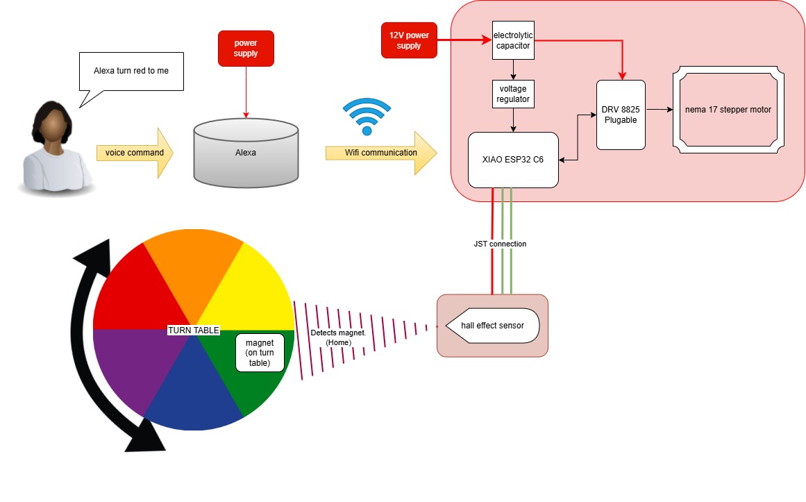
Working through the block diagram gave us a much clearer picture of how the electronics would be executed and how Alexa would integrate into the whole system.
On a personal note, I would love to have a version of this on my desk while doing craft work more like a tower with multiple layers so I can keep many things within reach. In my own design I would have just one home position so the compartments always rotate back to me.
References
-
Circuit Board Reference:
- USB-C PD Trigger Module | PDsink — YouTube
- DRV8825 Stepper Motor Driver with ESP32 — MicrocontrollersLab
- Kalyani RK — Week 9 | Fab Academy Kochi 2024
- Group Assignment — Week 9 | Fab Academy Kochi 2024
- Muhammad Chettiyam — Week 11 Input Devices | Fab Academy Kochi 2024
Hall Effect Breakout Board:
Electronics
To design the circuit board I referred to Kalyani RK's Week 9 documentation and the corresponding group assignment page . The key difference was the microcontroller their board used an ATtiny, but for this project we needed Wi-Fi capability to connect with Alexa, so we went with the Xiao ESP32-S3 .
Schematic Drawing
.jpg)
.jpg)
.jpg)
.jpg)
.jpg)
The schematic was designed to ensure stable power delivery and clear module connections. A voltage converter steps down the input voltage, while capacitors help smooth fluctuations. The LED acts as a simple power indicator, making debugging easier.
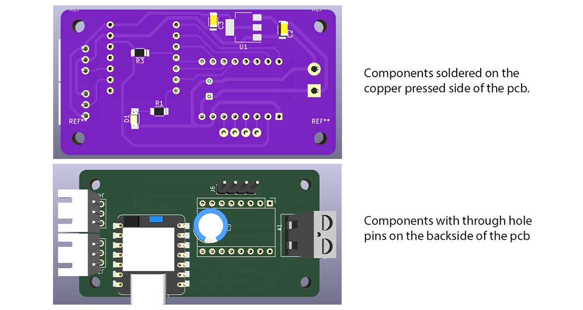
PCB Layout
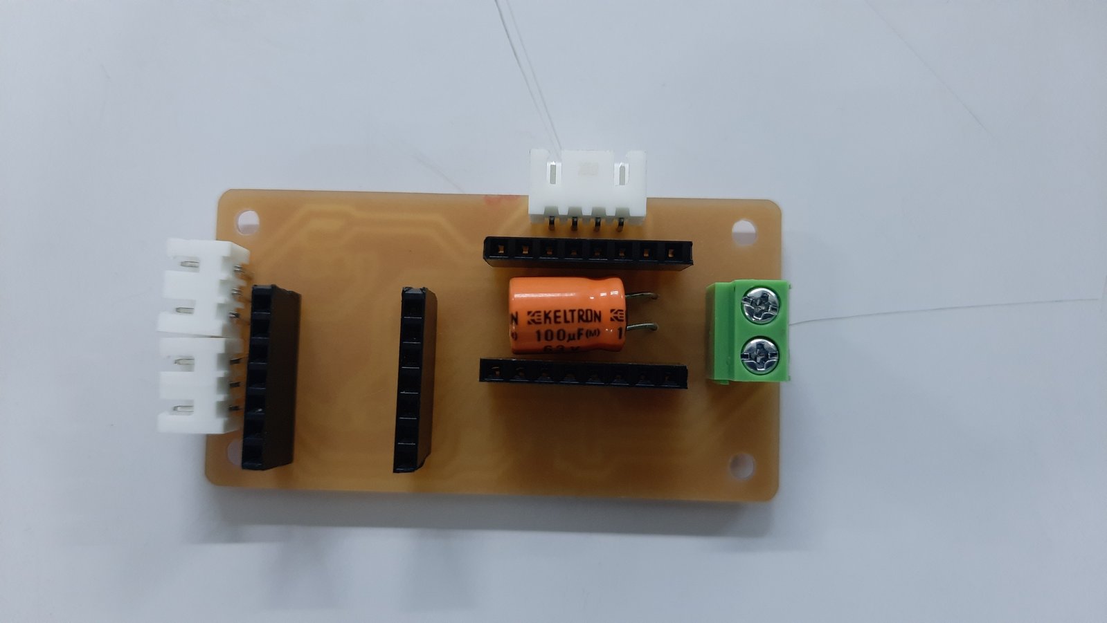
The PCB is single sided. Most of the pin connections use through hole components, so the Xiao, JST connectors, screw terminals, and motor driver are all placed on the back of the board. This allows their pins to be soldered directly on the copper side.
While designing the board, the power connections and the physical placement of the PCB within the assembly needed careful consideration. To understand this, I referred to the 3D model of the rotary table, focusing on the wire grooves and the intended mounting position.
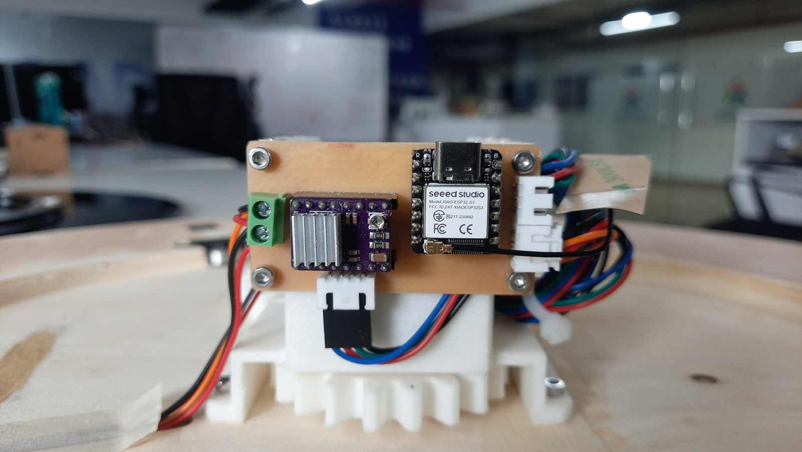
Initially, the plan was to place the PCB on top of the 3D printed motor frame. However, this later changed, and the PCB is now mounted along the vertical face of the motor frame.
To ensure accuracy, Abhishek shared the DXF file of the 3D printed motor frame. This allowed me to mill the PCB to match the exact size and shape, including the 3 mm mounting holes.
.jpg)
.jpg)
.jpg)
.jpg)
PCB 3D Model
The 3D model of the PCB done in KiCAD is shared to Abhishek, who was handling the design part of the machine.
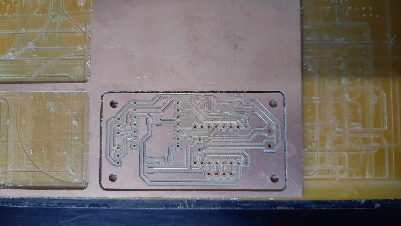
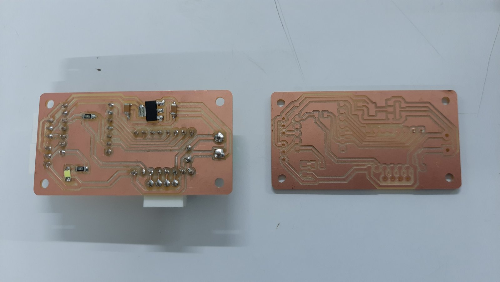
Milling
Board Fabrication and Assembly
The board was milled, assembled, and mounted on the rotary table for testing.
Breakout Board — Hall Effect Sensor
The AH49E Linear Hall Effect Sensor breakout board was designed based on a reference, but with one important difference. The original reference board used a hall effect sensor that required two capacitors 100 nF and 10 nF along with a resistor. The AH49E that we actually used only needs a single 100 nF capacitor, so the design was simplified accordingly.
Hall Effect Breakout Board Reference: Muhammad Chettiyam — Week 11 Input Devices | Fab Academy Kochi 2024
Hall Effect Breakout Board
.jpg)
.jpg)
.jpg)
.jpg)
The connection pins use through-hole mounting and are placed on the back of the PCB. The placement slot was designed with enough space for a JST connector and a groove for the wires to pass through cleanly. The hall effect sensor itself sits beneath the ring gear, while the magnet is mounted on the ring gear so the sensor can detect it as it rotates.

The hall effect sensor is placed such that it could detect the magnet placed on the gear. The JST pins are underneath, and the wires pass through the groove made on the board.
Components Used
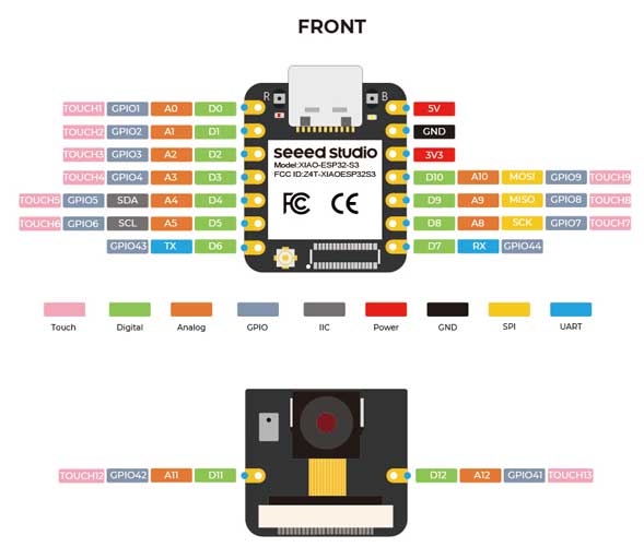
Xiao ESP32-S3
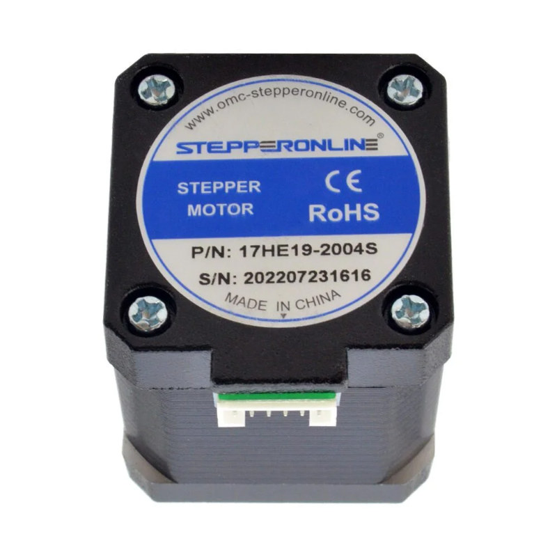
Stepper Motor — NEMA 17 17HS19-2004S1
The NEMA 17 is a bipolar stepper motor with a high torque of 59 Ncm, which makes it well suited for driving a rotating table under load.
Buy: OMC StepperOnline — NEMA 17 17HS19-2004S1
NEMA 17 17HS19-2004S1 Datasheet: omc-stepperonline.com — 17HS19-2004S1.pdf
Driver Module — DRV8825
Motors are power-hungry devices and can draw more current than is safe without protection. To address this, a motor driver is used to set the current limit and protect the motor. The DRV8825 also offers flexible step resolution: six options in total: full-step, half-step, quarter-step, eighth-step, sixteenth-step, and thirty-second-step modes. Each mode divides the motor's 200 steps per revolution differently, allowing for various levels of movement precision and smoothness.
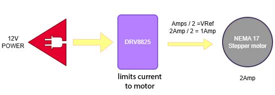
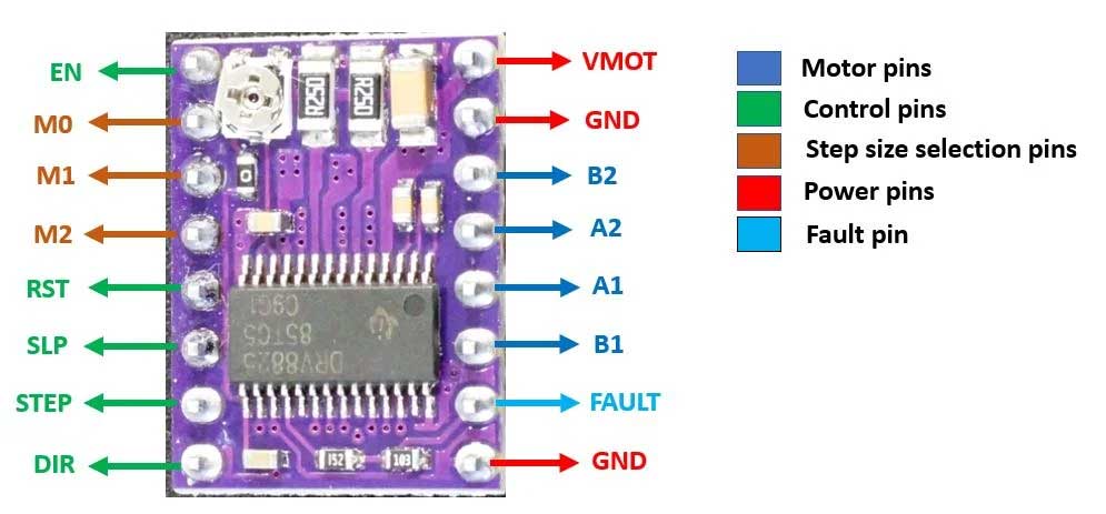
Image source:
MicrocontrollersLab — DRV8825 Pinout
References:
DRV8825 with ESP32 Tutorial — MicrocontrollersLab
|
DRV8825 with Arduino Tutorial — Last Minute Engineers
Electrolytic Capacitor
The capacitor used is a 63 V 100 µF polarised electrolytic capacitor 8 × 12.5 mm from Keltron. It is placed between the screw terminal and the motor driver, positioned as close as possible to the driver's power and GND pins to suppress voltage spikes. Since the DRV8825 is pluggable rather than soldered directly, there is enough clearance underneath it to seat the capacitor comfortably.
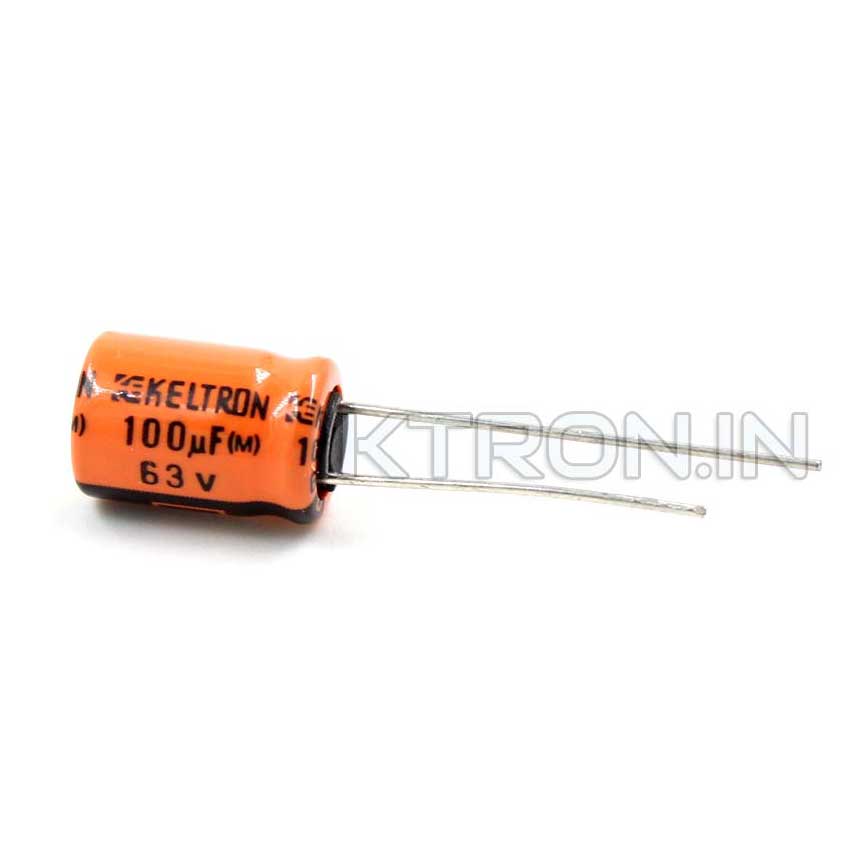
A through hole electrolytic capacitor is used. This is a 63V 100uF electrolytic capacitor from Keltron. It has a diameter of 8 mm and a length of 12.5 mm. Its pitch is 3.5 ± 0.5 mm. It is polarized. It has cathode (negative) and anode (positive) legs. The anode is the longer leg. The negative leg is always marked with a visible strip on the side of the capacitor body.
Source: Ktron 63 V 100 µF Electrolytic Capacitor Keltron
Hall Effect Sensor — AH49E Linear Hall Effect Sensor
The AH49E is used as a digital switch sensor in this project. Only one pole of the magnet, the south side, triggers the sensor. When the magnet passes over it, the sensor is either activated or deactivated depending on the polarity detected. In the context of this machine, the hall effect sensor is used to home the compartment, meaning it detects when the designated home position has been reached so the table knows exactly where it is in its rotation.
Reference:
Understanding the Hall Effect Sensor: A Complete Guide — Evelta
Datasheet:
AH49E Datasheet — PDF
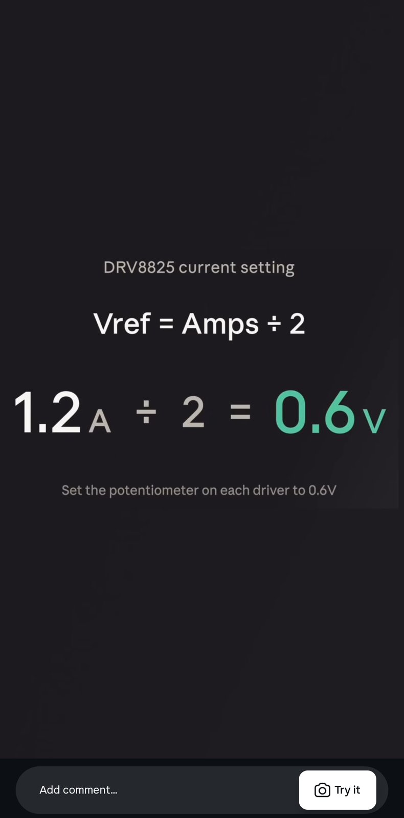
The potentiometer on the DRV8825 motor driver is tuned to give an output of 0.6V.
Potentiometer
learnings : The shape and size of the pcb directly affects the design, one has to aware of the components used and where they are placed on the pcb. a continuous coordination was necessary bwteen the machine designer and the pcb design