week 12 Mechanical design, machine design
Week 12 focused on machine design, and unlike previous weeks, this was a group-based project where multiple systems had to come together - mechanical, electronics, firmware, and interaction.
To begin with, we referred to previous years’ documentation to understand the scope and limitations of what could be realistically achieved within the given time.
During discussions around tabletop systems, especially setups where objects are arranged or shared, I was reminded of the rotating lazy Susan used in the Chinese dining contexts. That became the starting point for the idea:
Roles and Responsibilities
My responsibilities in this project included the fabrication and assembly of the rotary table, capturing photos and videos during the build process, editing the media content, and documenting the complete workflow.
Click here to view the group documentation of Group Assignment
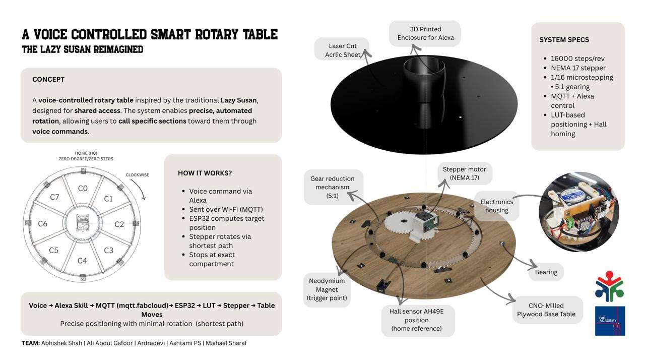
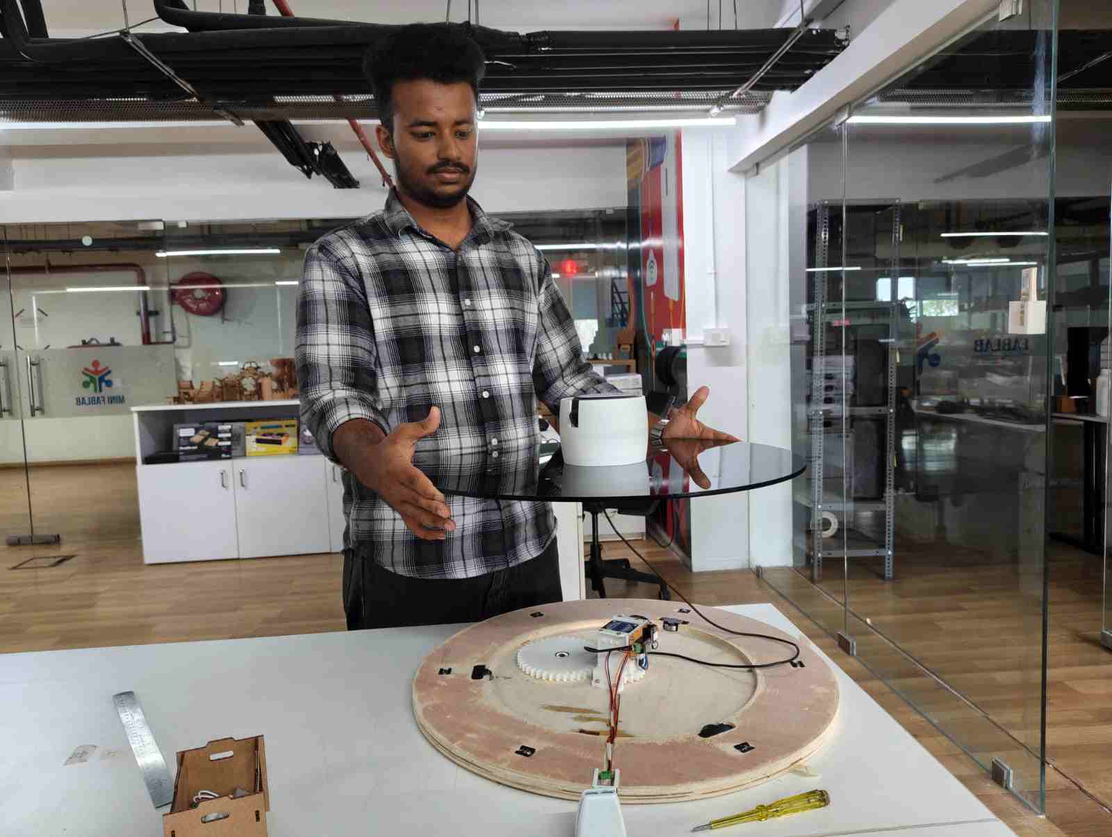
We built a voice-controlled smart rotary table, inspired by the traditional Lazy Susan, focusing on the idea of shared access through automation. The system is a motorized platform divided into compartments, where each section can be called toward a user using voice commands through Alexa. Once a command is given, it is sent via MQTT to an ESP32, which calculates the exact position using a lookup table. The table then rotates using a stepper motor, taking the shortest path and stopping precisely at the requested compartment.
To ensure accuracy, we use a homing mechanism with a hall sensor that defines a fixed reference point every time the system starts. This allows consistent and repeatable positioning.
The project integrates mechanical design, electronics, and firmware into a single system, and can be adapted beyond this setup, for example, organizing tools or materials in a workspace.
Overall, it explores how simple automation can make shared objects more interactive and efficient.
System Definition
The system was defined as:
- Circular table (~55 cm diameter)
- 6 compartments (60° separation)
- Multiple fixed user positions (homes)
- Central stepper-driven mechanism
Standard Parts and Materials Used
| Item | Description | Quantity | Purpose |
|---|---|---|---|
| M3 × 4 mm Allen Key Screws | Standard socket head cap screws | 10 | Assembly and fastening of mechanical parts |
| 12 mm Plywood | Birch plywood sheet | 2x2 feet | Main structural frame components |
| 6 mm Acrylic | Black Acrylic sheet | 4x2 feet | Secondary structural and support parts |
| 608ZZ Bearing | 8 × 22 × 7 mm shielded ball bearing | 3 | Rotating shaft support and smooth motion |
| 625ZZ Bearing | 5 × 16 × 5 mm shielded ball bearing | 6 | Guide roller and motion support |
To address the instructor's feedback, I have included a list of the standard parts and materials used in the design.
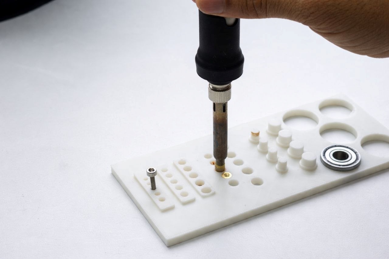
Testing Jig for Screw Hole Alignment, Heat Insert Installation, and Bearing Fitment
Purpose of Testing
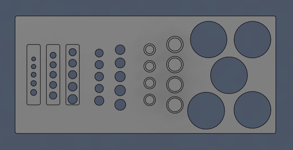
The purpose of the screw hole test is to determine the appropriate tolerances required for proper screw fitting, heat-threaded insert installation, and bearing press-fit. This ensures accurate assembly, secure fastening, and optimal mechanical performance of all components.
This jig is designed in Autodesk Fusion to check press-fit accuracy and alignment of components.
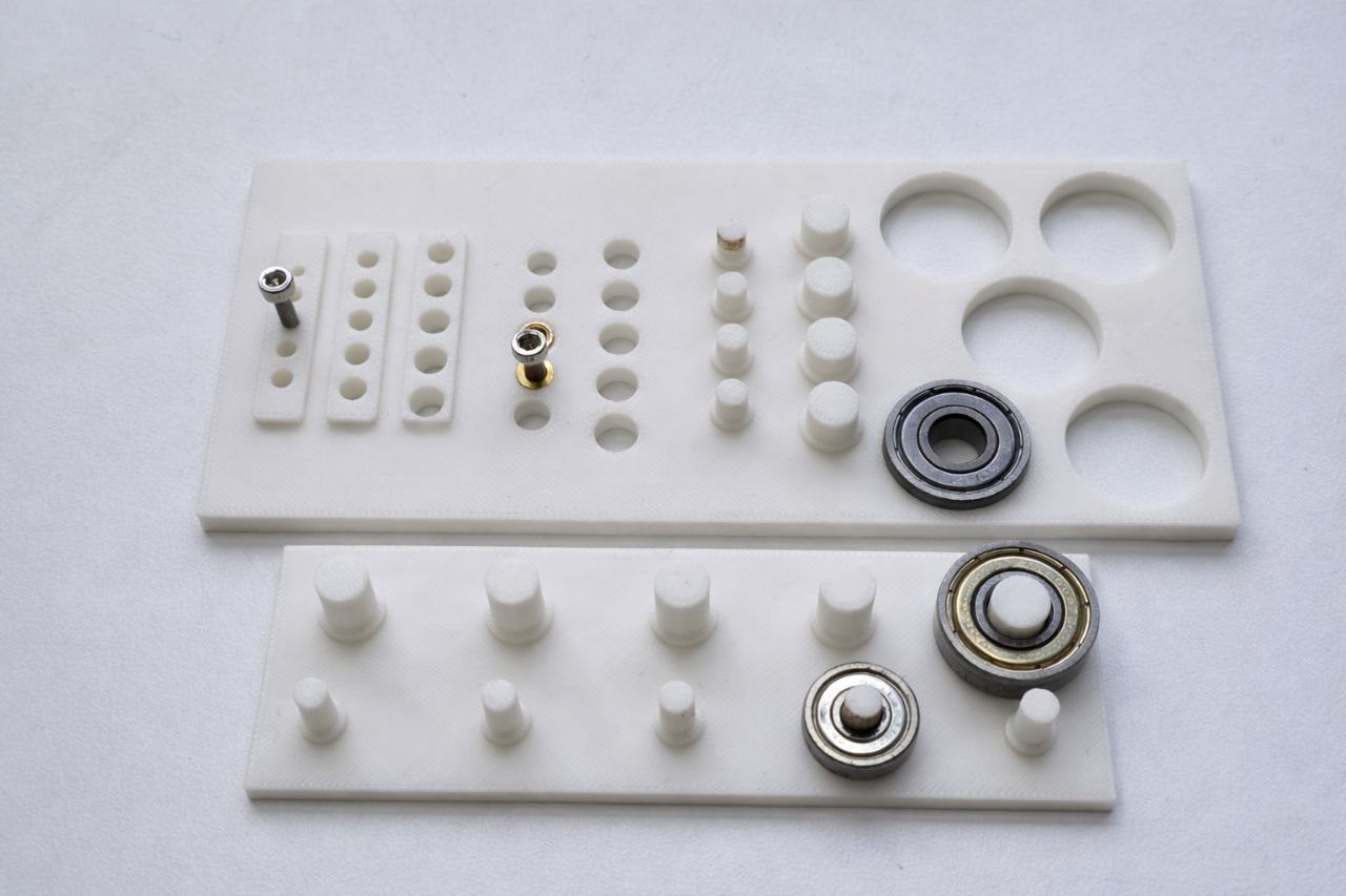
Components Tested
- Direct screw inserts: M3, M4, M5
- Heat-set inserts (soldering method)
- Bearings:
- 608ZZ (inner & outer fit)
- 625ZZ (inner fit)
Issues Faced
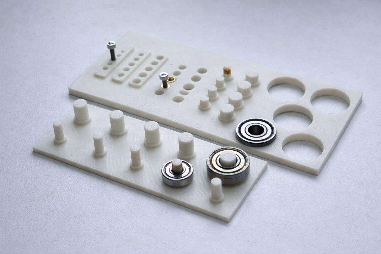
1. Bearing Fit Issue (Design Error)
- 608ZZ outer diameter slot was too tight in the initial design.
- Issue identified only after 3D printing.
- Insufficient internal clearance for bearings.
- Solution: Reprinted jig with corrected tolerances — fit is now proper.
2. Heat Insert Availability & Size Mismatch
- Only M4 screws and M4 heat inserts were available in the lab.
- M3 and M5 inserts were not available for testing.
- M4 insert dimensions did not match the designed hole size.
- M3 design worked correctly based on standard sizing.
Final Corrected Dimensions
- M3 heat insert hole: 5.20 mm
- M4 heat insert hole: 5.00 mm
- 608ZZ Bearing:
- Outer diameter fit: 22.10 mm
- Inner diameter fit: 8.20 mm
- 625ZZ Bearing:
- Inner diameter fit: 5.10 mm
Key Learnings
- Always verify component dimensions physically before finalizing CAD design.
- Heat-set inserts vary slightly by manufacturer.
- Small tolerance changes (~0.1 mm) significantly affect press-fit performance.
3D Printing Preparation
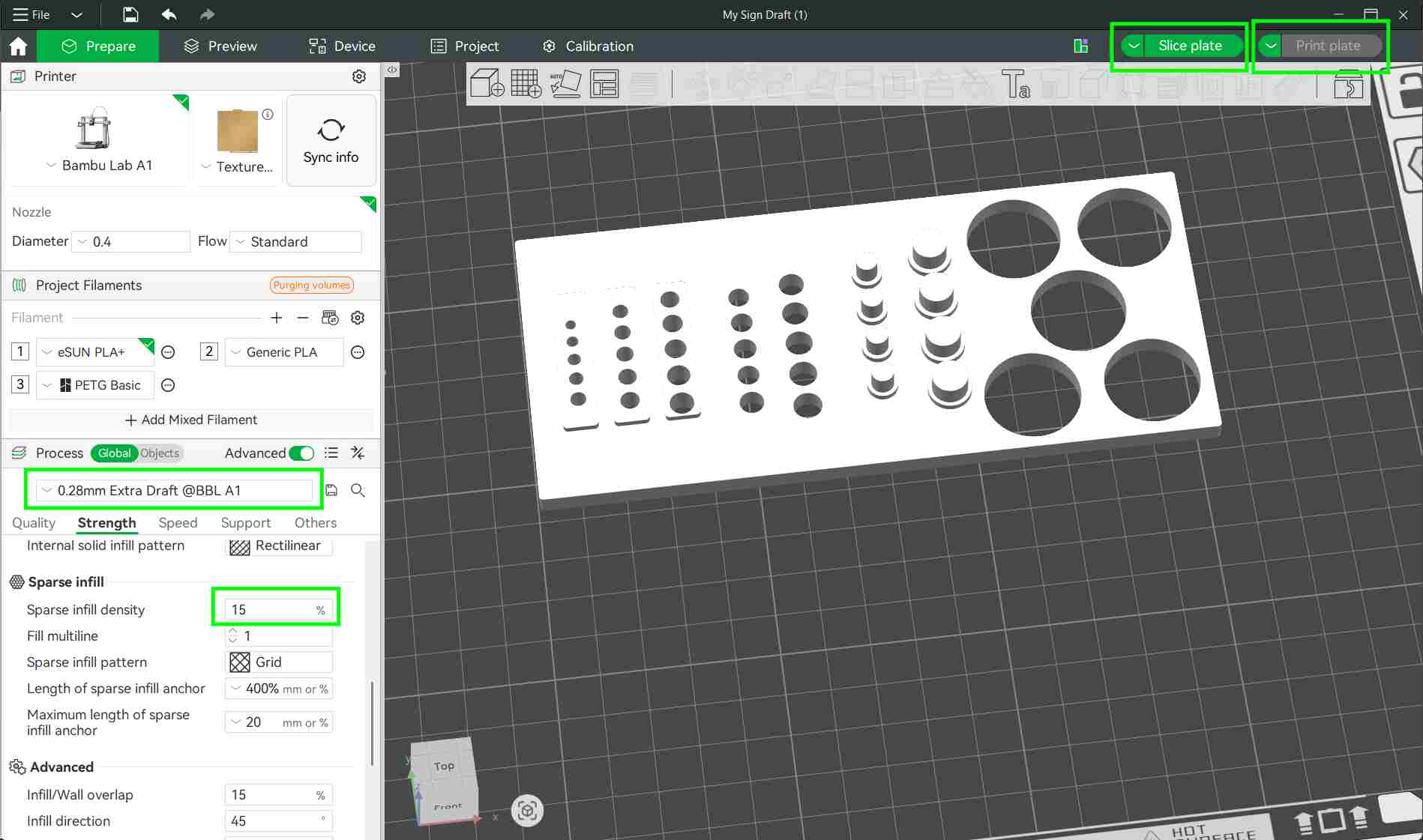
The design files were converted into STL format and imported into Bambu Studio for slicing.
In Bambu Studio, the model was prepared for printing by setting the layer height to 0.28 mm and adjusting the infill density to 15%. These settings provided a balance between print speed, strength, and material usage.
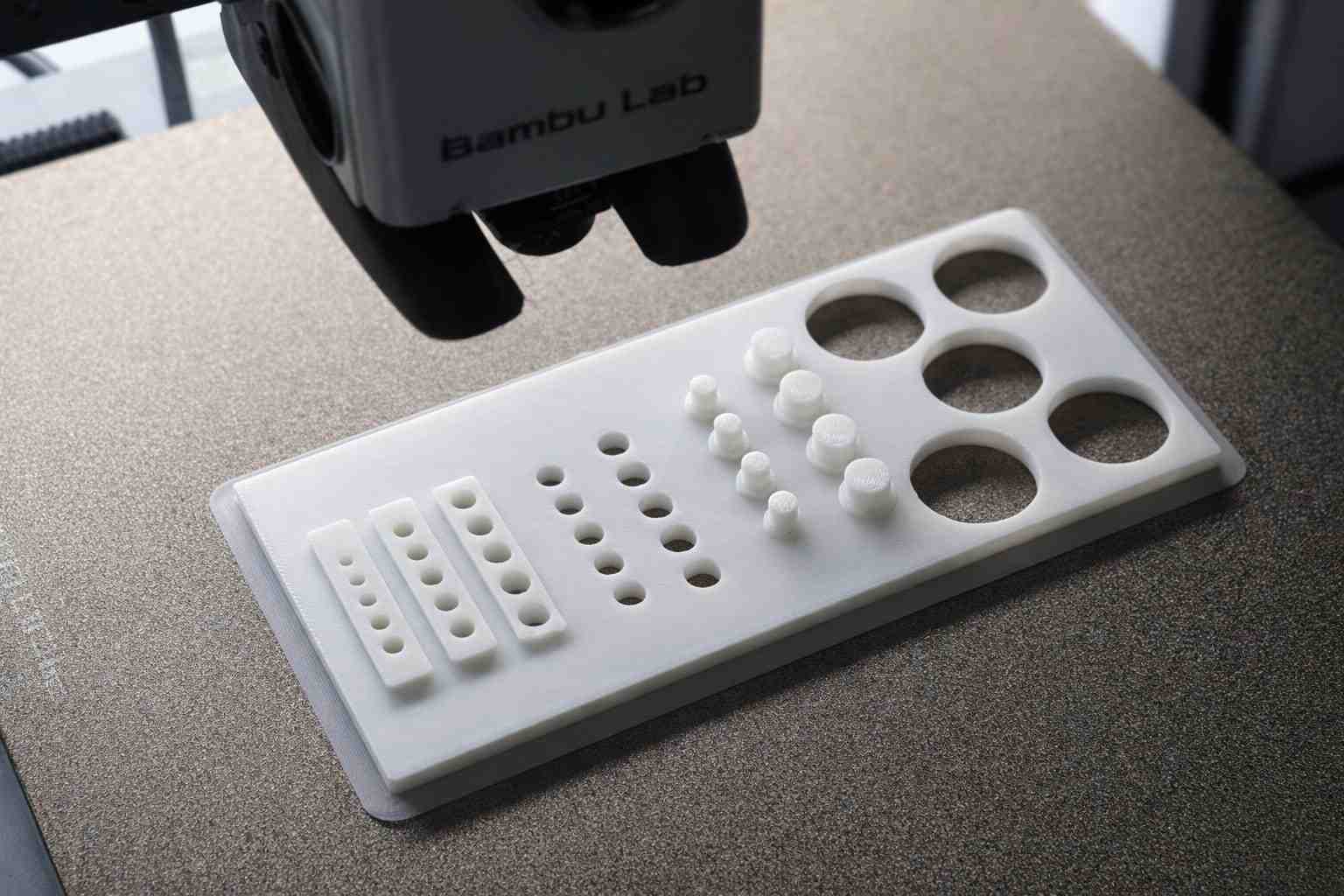
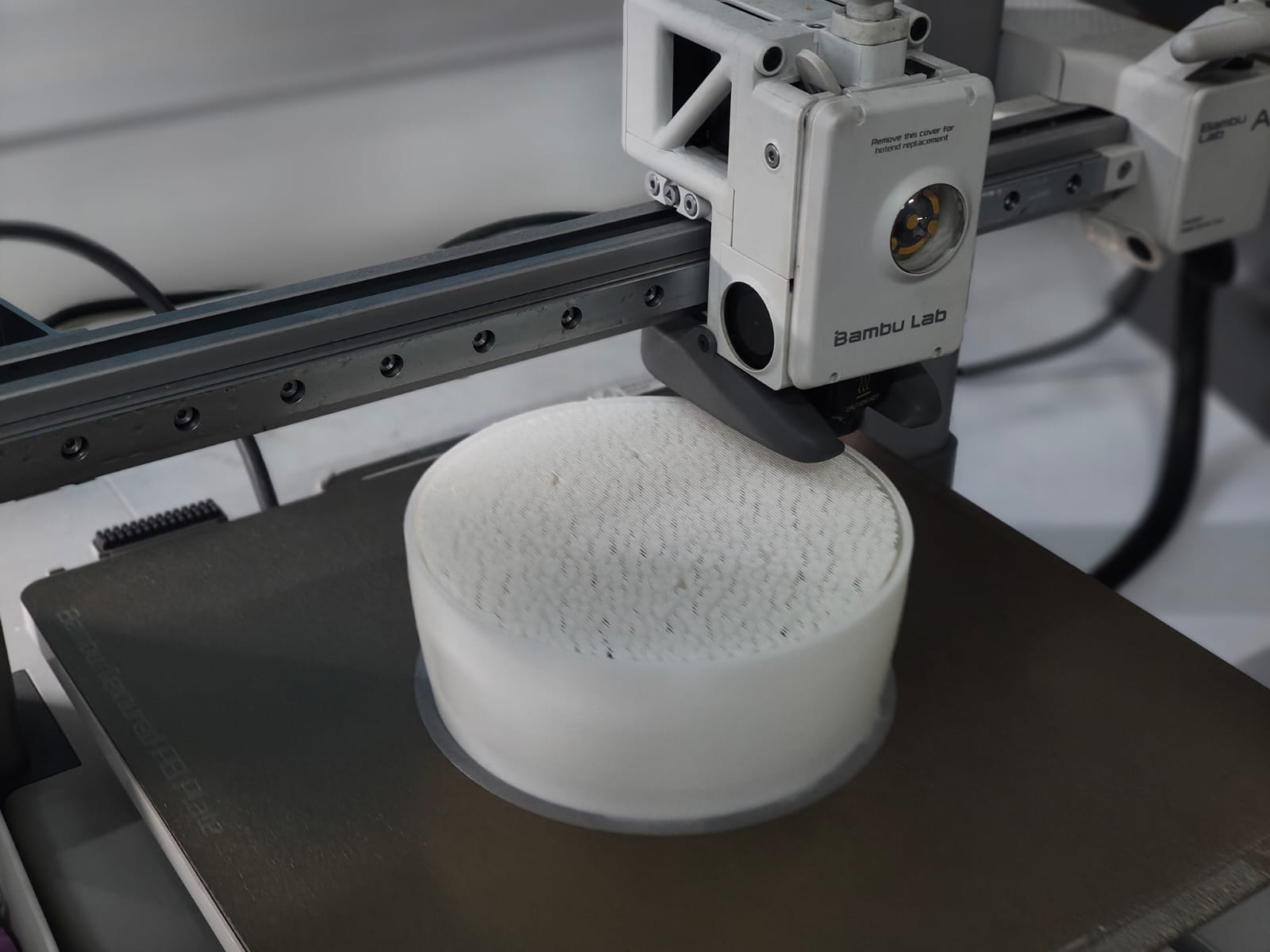
3D Printing Process
The test model was printed using the Bambu Lab A1 3D printer.
After slicing the model in Bambu Studio, the build plate was prepared and the "Print Plate" option was selected.
The file was then sent to the printer using the "Send File" option. Once the file was successfully transferred, the printer received the job and began printing the model.
Heat Insert Installation
The model was printed using PLA material, with a nozzle temperature set to 210 °C, ensuring good layer adhesion and print quality.
To install the heat-set inserts, a soldering iron with an appropriate tip was used. The correct end tool was selected based on the insert size to ensure accurate alignment and proper heat transfer.
The insert was placed into the designed hole, and controlled heat was applied. This allowed the insert to melt into the plastic and seat firmly without deforming the surrounding material.
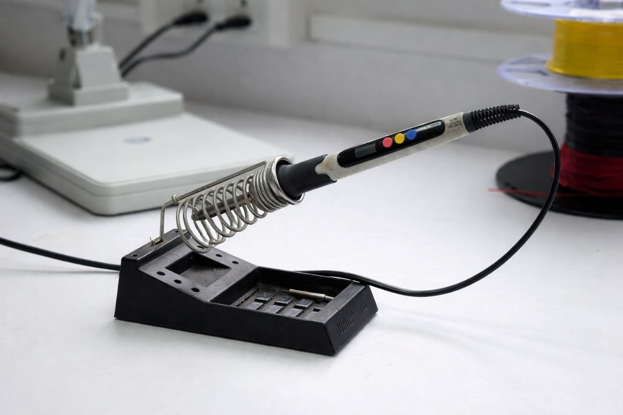
use appropriate heat insert bit and place over the hole make soldering iron to temperature to 210°C and keep it there for a few seconds
Final Jig Output
Group Assignment Jig
Final Jig Assembly
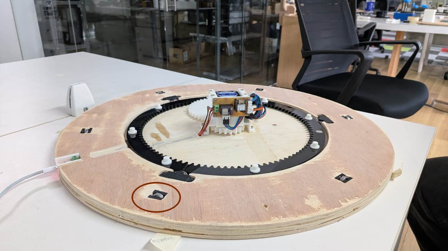
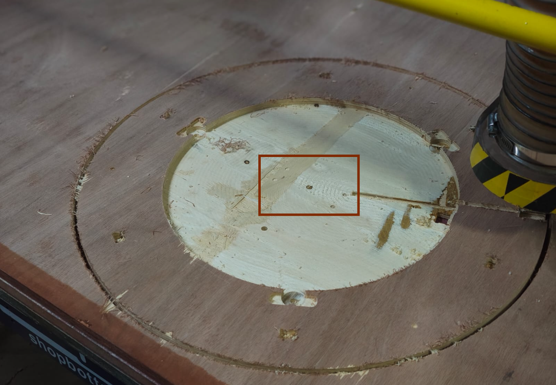
Bottom Plywood
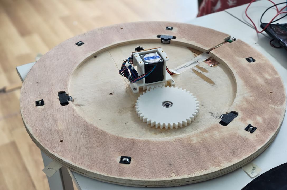
This is the main component of the turn-table because it holds entire mechanisms together.
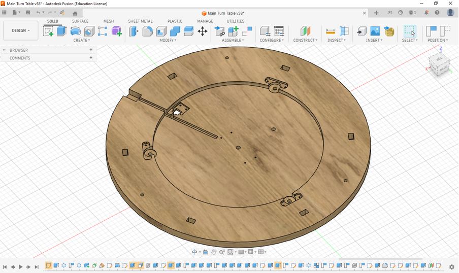
For detailed CAD files, assembly references, and project documentation, visit Abhishek Shah's Documentation .
The plywood components were machined using a ShopBot CNC Router. An 18 mm plywood sheet was used for the fabrication process. Both 6 mm and 3 mm end mills were utilized to achieve the required cuts and details. The complete milling operation took approximately 2 hours to finish.
After milling Ply
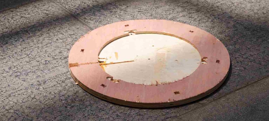
After the CNC milling process, the edges and surfaces of the plywood components were finished using a Bosch Orbital Sander to remove rough edges and improve the overall surface quality. Unfortunately, I forgot to capture photos and videos during this sanding process.
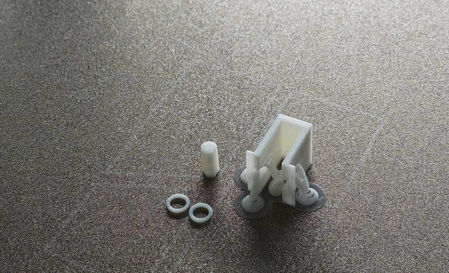
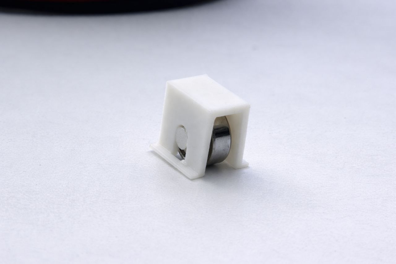
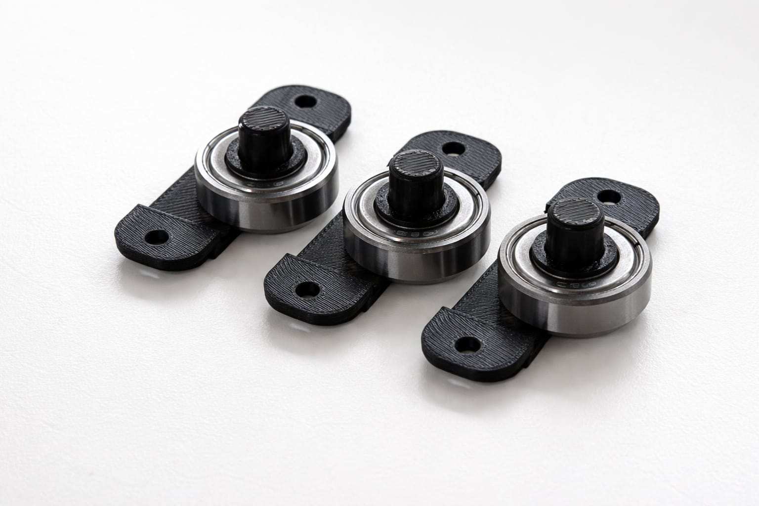
Guide Roller
Guide Roller Assembly – A small roller wheel mounted inside a housing, used to guide and support smooth linear movement along a track.
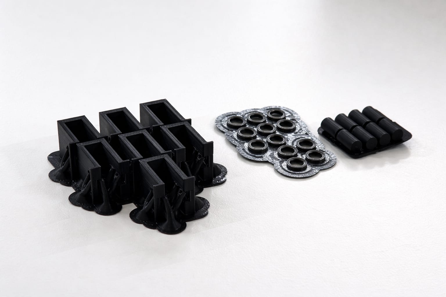
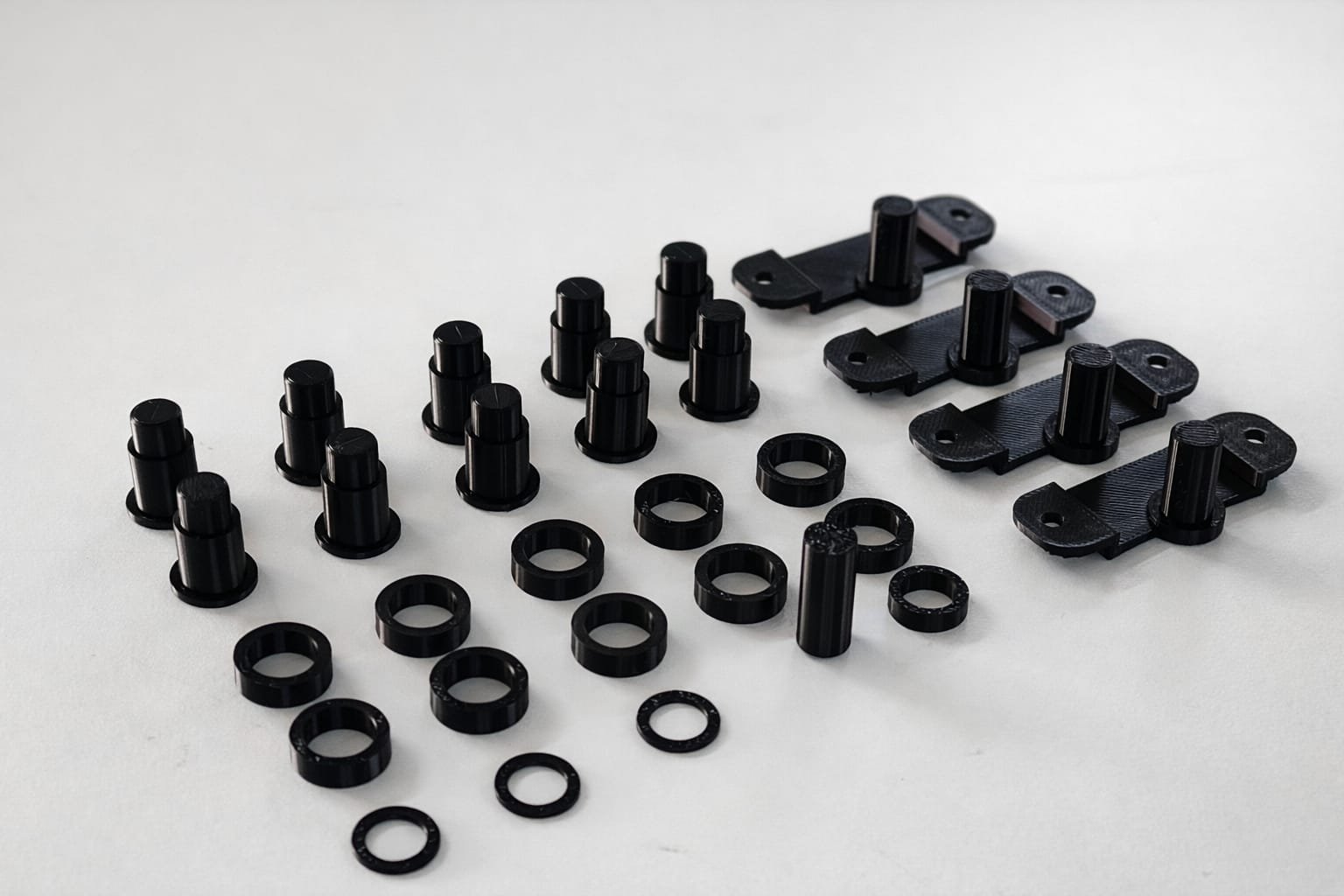
components needed to make Guide Roller.
These components were manufactured using the Bambu Lab A1 3D printer. The printing material used for this process was eSUN PLA, selected for its ease of printing, dimensional accuracy, and good surface finish.
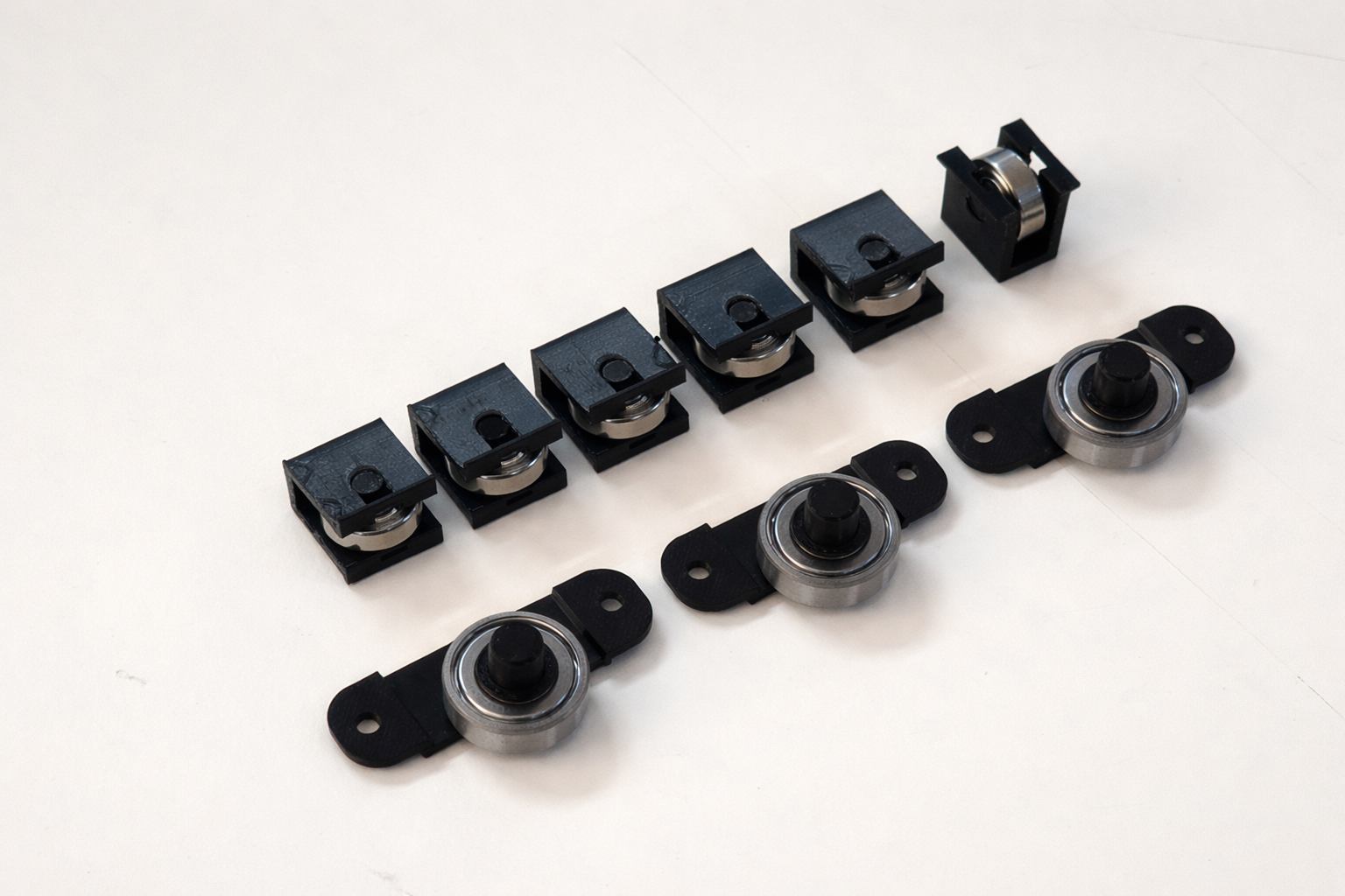
Post Processing
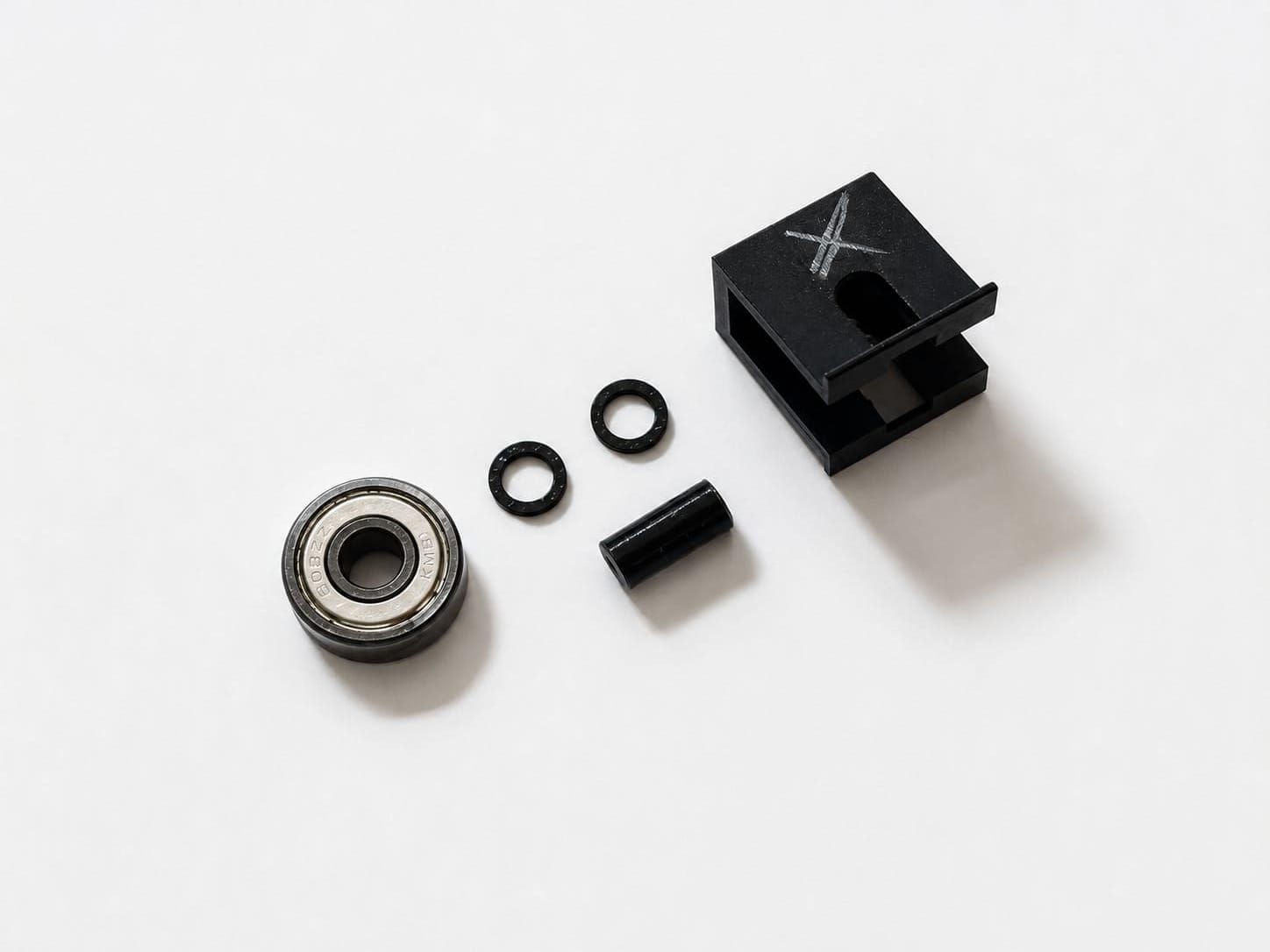
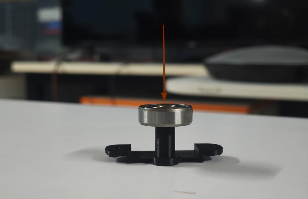
Assemling The Guid Roller
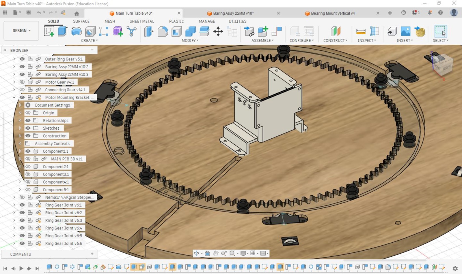
After Assembling .And this image shown model is not used for final product this model is used for testing and analysing
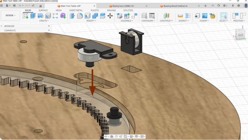
This CAD model illustrates the assembly and mounting method used to fix the vertical bearing onto the plywood structure. For a more detailed understanding of the design, assembly process, and CAD development, refer to Abhishek Shah's Week 12 Documentation . The complete CAD files for this project can also be downloaded from his documentation for reference and further study.
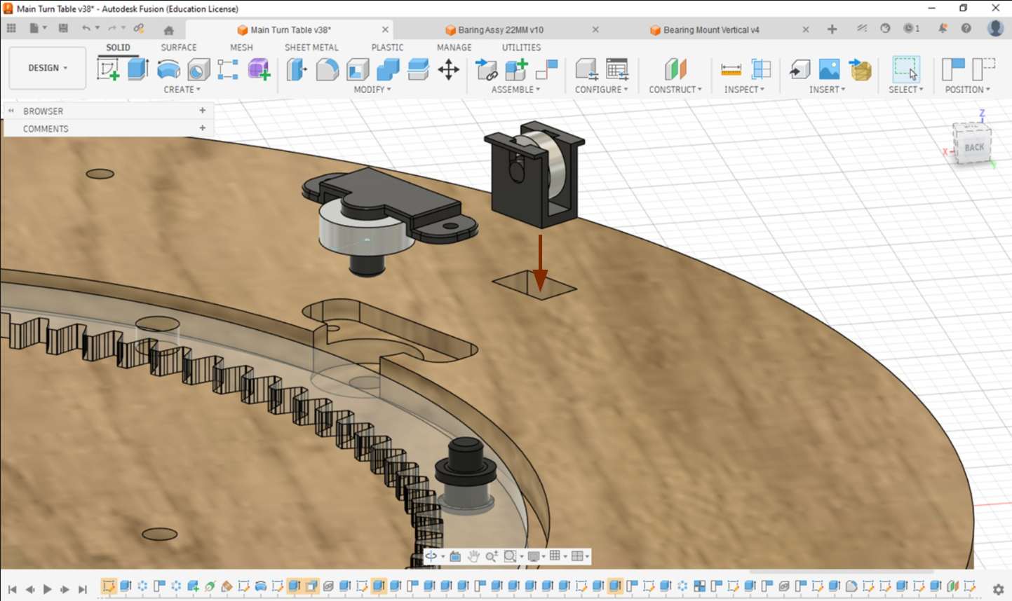
Now you can Directley insert the model into it .its a press fit type model

Here we Want 6set of vertical bearing Systems we to 1 extra for safety.after finaling with test print we printed 7 of them
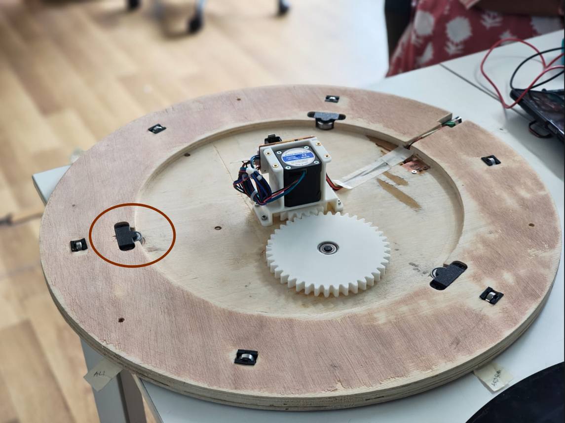
this is after post processing and assembling
This is the final product after fixing the vertical bearings.I forgot to take fixing videos
Horizontel Bearing
It will Help to rotate smooth
For detailed CAD files, assembly references, and project documentation, visit Abhishek Shah's Documentation .
Just push bearing Down itwill go inside and insert spacer
Just press to playwood it will fix there some areas i just sanded using sand paper because plywood thickness is not accurate and finising of playwood is not good
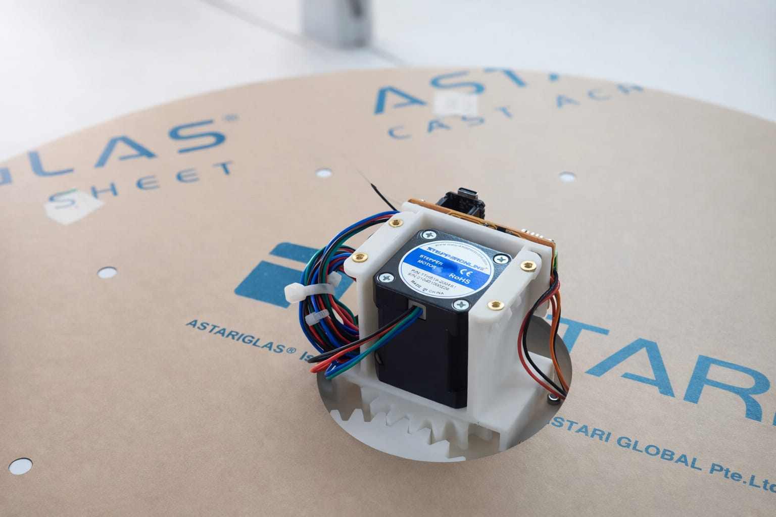
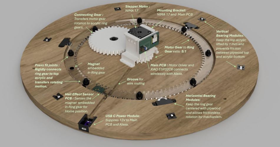
Nima17 Mounting
to support nima 17 with playwood we made a mounting bracket
For detailed CAD files, assembly references, and project documentation, visit Abhishek Shah's Documentation .
Using 3d printer we made this mount
The plywood components were machined using a ShopBot CNC Router. During the milling process, slots were incorporated into the design to facilitate the accurate mounting and fixation of the assembled components.
I forgot to take videos and photos of fixing Mount.using m3 scerew idirectley drilled to playwood
Next I inserted m3 heat insert for mounting outer covering.The inserting process is on top of documentation
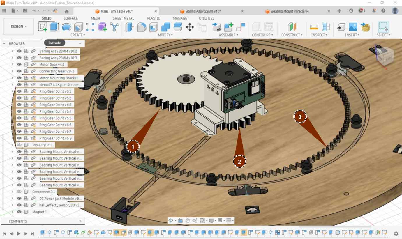
Gear
For detailed CAD files, assembly references, and project documentation, visit Abhishek Shah's Documentation .
Gear 1 and Gear 2 were manufactured using 3D printing technology. The larger Gear 3 was fabricated from 6 mm black acrylic using a Trotec Speedy 400 laser cutter. This combination of 3D-printed and laser-cut components provided the required strength, precision, and dimensional accuracy for the gear assembly.
The components were manufactured using a Bambu Lab A1 3D printer. The models were prepared and sliced using Bambu Studio. For printing, white eSUN PLA filament was used. The print settings included a wall thickness of 2 mm and an infill density of 10%, providing a good balance between strength, material usage, and print time.
Insert bearing into 3d printed big gear its press no need any tool for inserting and small gear also pressfit type so fix it into Nima17
Large Gear
I forgot to take images and videos of inserting spacer into gears.its very simple to install keep ring spacer one side through opposite side insert cylinder shaped insert through out,press from each side make it tite maximum
NOw its working Perfectly
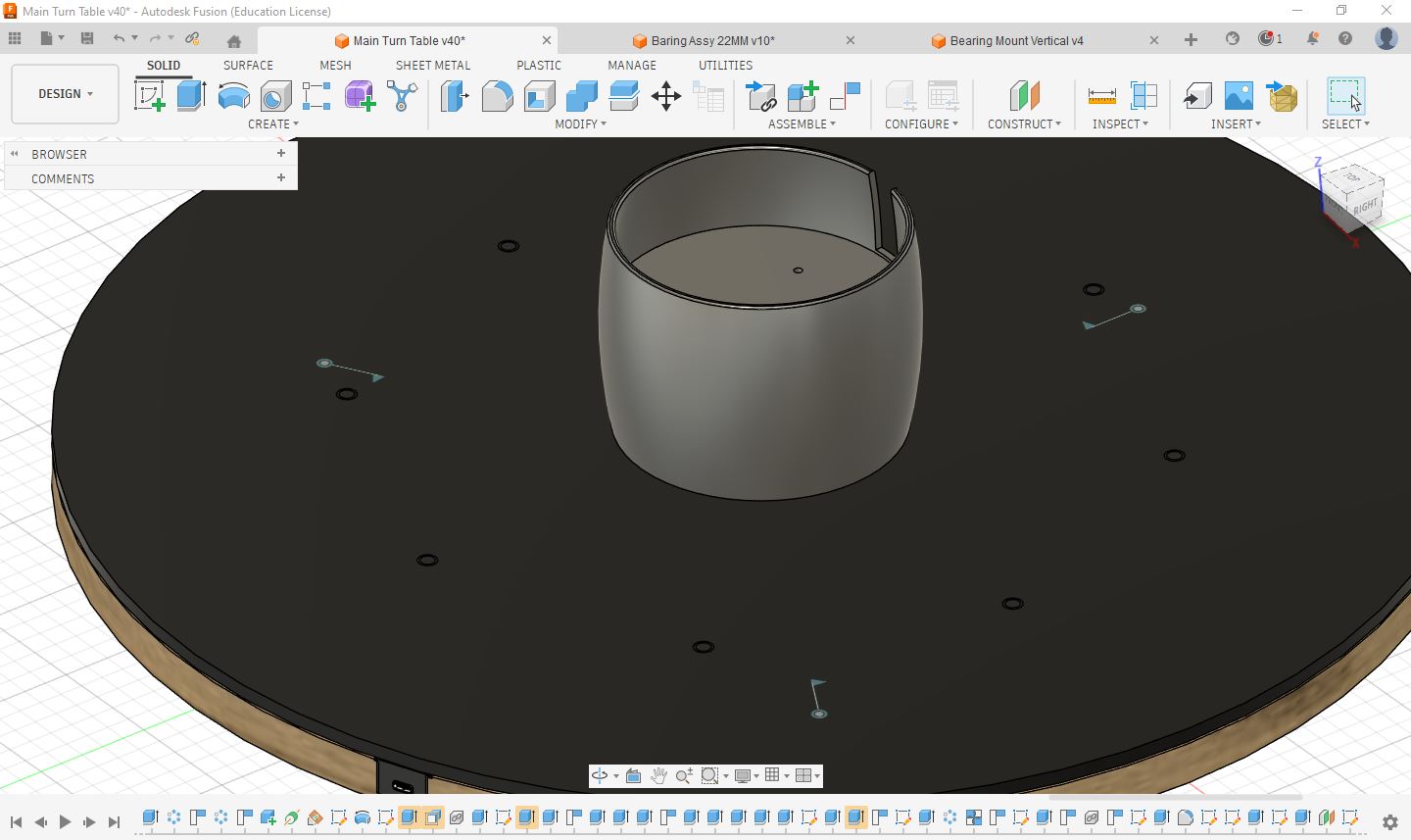
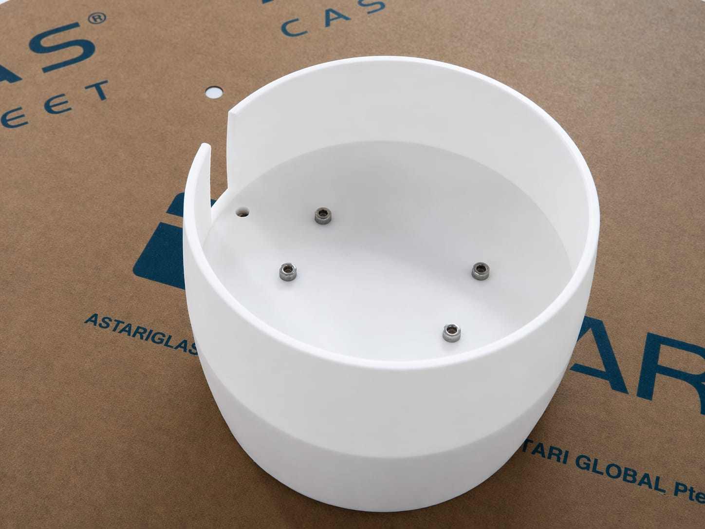
Enclosur
TO keep neet clean we put enclure to void tangleing wires and and need to place Alexa on top
The components were manufactured using a Bambu Lab A1 3D printer. The models were prepared and sliced using Bambu Studio. For printing, white eSUN PLA filament was used. The print settings included a wall thickness of 2 mm and an infill density of 10%, providing a good balance between strength, material usage, and print time.
Using m3 Screw insert it andd tite it so the enclosure will not move and shake.
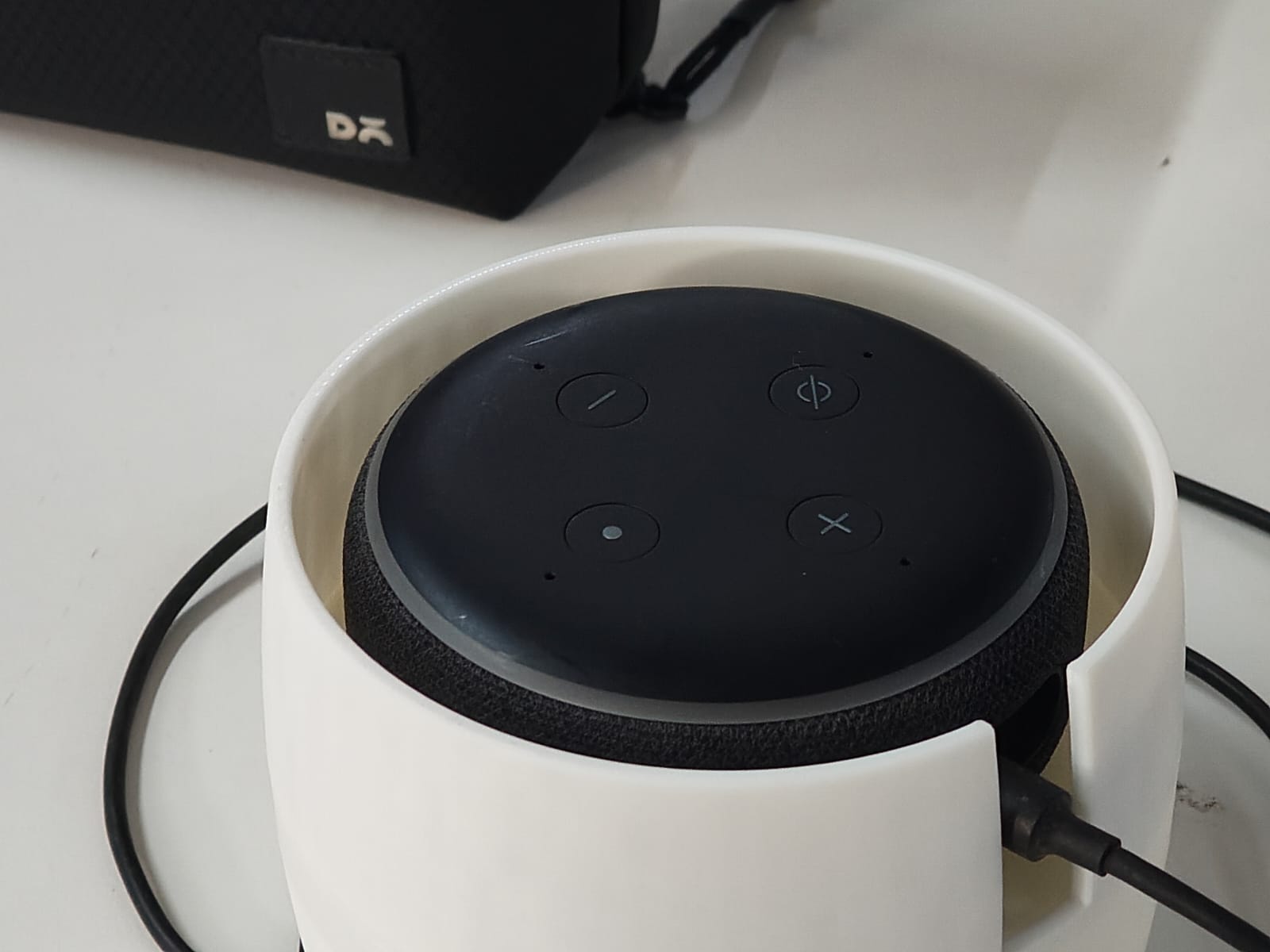
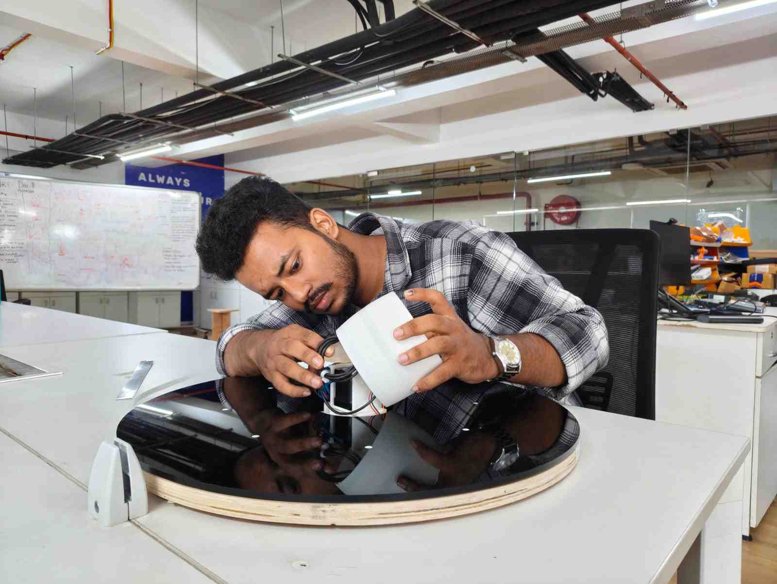
Final Fixing
Gear fixed to top acrylic using 3d printed spasers and inserts
After that top sheet just keep on top of plywood then just tilt side by side then then big gear get contact with nima 17 gears
After connecting all internall pcb connection wiremanagement keep enclosure put m3 screws on top of it and tite it
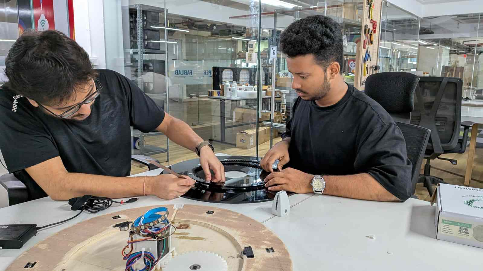
My Contribution
During Week 12 – Machine Making, we worked as a group of five to design and build a machine. My role focused on both documentation and hands-on fabrication support throughout the project.
Responsibilities
- Developed and maintained complete group documentation.
- Captured photos and videos of each stage of the process.
- Prepared and organized manufacturing materials.
- Assisted in CNC machining operations.
- Performed 3D printing of required components.
- Handled post-processing including cleaning, finishing, and fitting adjustments.
- Participated in the final assembly of the machine.
Reflection
This role allowed me to actively contribute to both the technical and documentation aspects of the project. I gained hands-on experience in digital fabrication processes while ensuring that the workflow was clearly recorded and presented. This improved my understanding of coordination between design, manufacturing, and assembly in a team-based environment.
Conclusion
We successfully completed our rotary tool table as a team. Each member contributed effectively, ensuring that all stages—from design to fabrication and assembly—were completed smoothly.
The system was successfully integrated with Alexa , allowing voice-based control of the table.
Throughout this project, we learned valuable lessons in digital fabrication, including CNC machining, 3D printing, tolerance management, and assembly techniques. This experience also improved our teamwork, problem-solving, and practical implementation skills.
Hero Shots
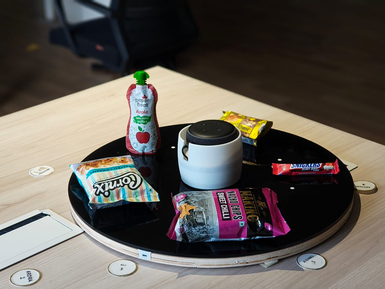
I would also like to express my gratitude to our instructors and mentors: Jogin Francis, Sreyas George, Ashish Joy, and Saheen Palayi.
References
- ChatGPT – https://chat.openai.com/
- Fab Academy 2025 – https://fabacademy.org/
- Ancy Roshan – Week 12 Documentation – View Page
- Autodesk Fusion – Fusion 360
- Bambu Studio – Bambu Studio
- ShopBot CNC – ShopBot
- Laser Cutting – Speedy 400 – Speedy 400