Objectives
- design a machine that includes mechanism+actuation+automation+application
- build the mechanical parts and operate it manually
- actuate and automate your machine
- document the group project and your individual contribution
Mechanical design, machine design
Velichappadu (വെളിച്ചപ്പാട്)
We had several intense brainstorming sessions before finalizing the idea for Velichappadu. Initially, we considered building a claw machine that could support multiple game modes. However, after a lot of discussion, feasibility checks, and analysis, we decided to pivot and focus on a light painting machine. This new direction excited us because it was both technically challenging and creatively rewarding. Velichappadu was a light painting machine based on an X-Y core mechanism. Light painting is a photographic technique where a light source is moved in front of a camera using long exposure to create beautiful trails. Since this was a new concept for me, I had a great opportunity to explore and learn about long exposure photography and how motion control translates into visual art. Throughout the project, I supported the team wherever I could. Whether it was testing, assembling, writing, or just being a second pair of hands, I stayed involved from start to finish.
machine week group assignment pageScrew hole Test
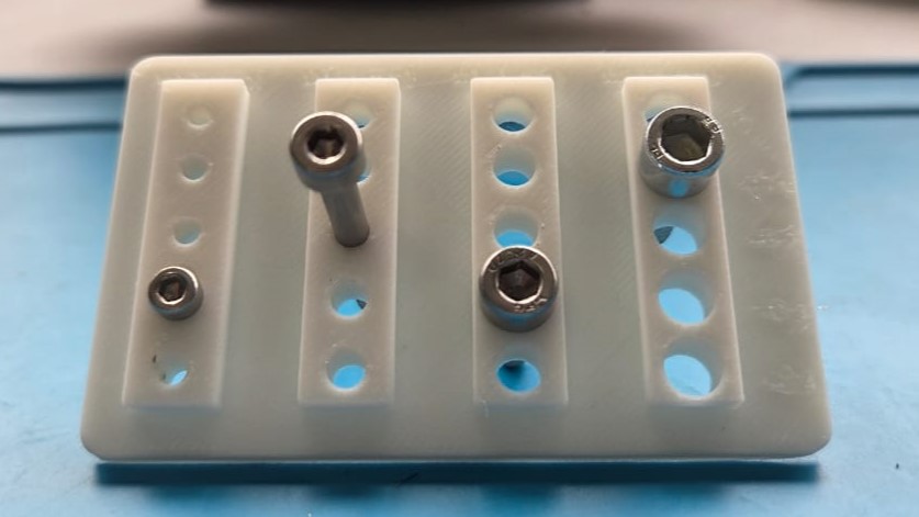
The purpose of a screw hole test is to determine the appropriate tolerance, screw fit, and optimal hole diameter for screw holes in 3D models or other application.We needed to test for M3 (3mm), M4 (4mm), M5 (5mm) and M6 (6mm) screws. 3D design was made in fusion.
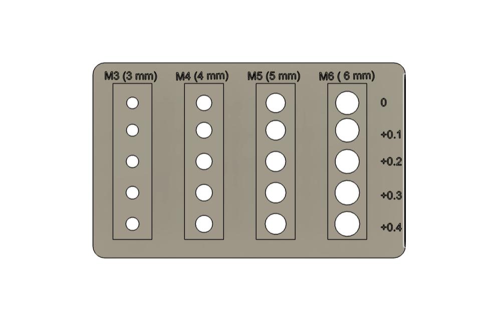
To design the test jig, I started by creating a 50 × 80 mm rectangle and extruded it to form the base. Then, I placed four equally spaced rectangles on the surface, each measuring 10 × 40 mm. Inside each of these rectangles, I added a circular hole with diameters of 3 mm, 4 mm, 5 mm, and 6 mm respectively. Since 3D printing is an additive process, the actual fit often requires slightly more clearance than the nominal (or exact) value due to material buildup and printer tolerances. So for each hole, I also created a slightly larger versions—increasing 0.1 mm bigger in diameter— downwards. Then the circles are cut away from the jig.
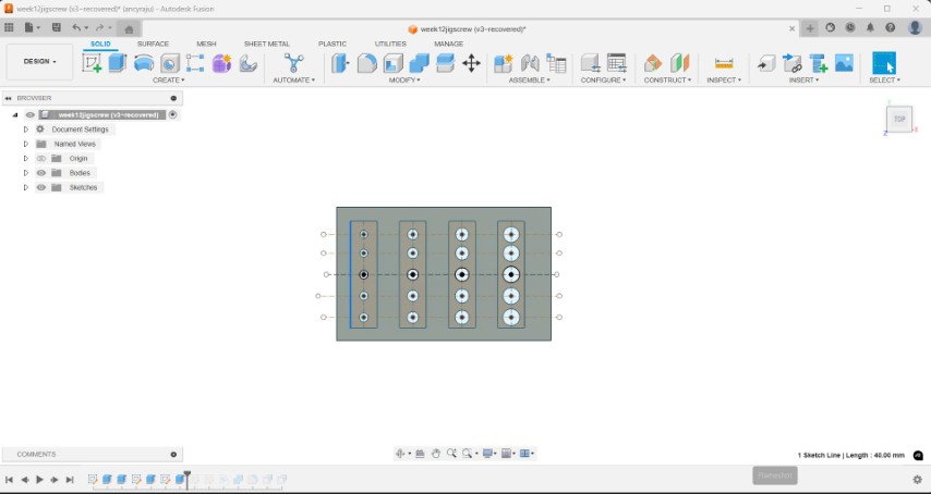
Then I labeled each hole with its diameter value and applied chamfers to the edges
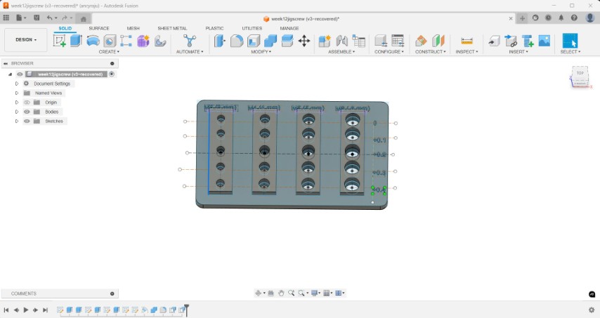
The files are then converted to step file and opened in bambu slicer.
Then I opened the file in Bambu Slicer, set the layer height to 0.24 mm, and adjusted the infill density to 15%
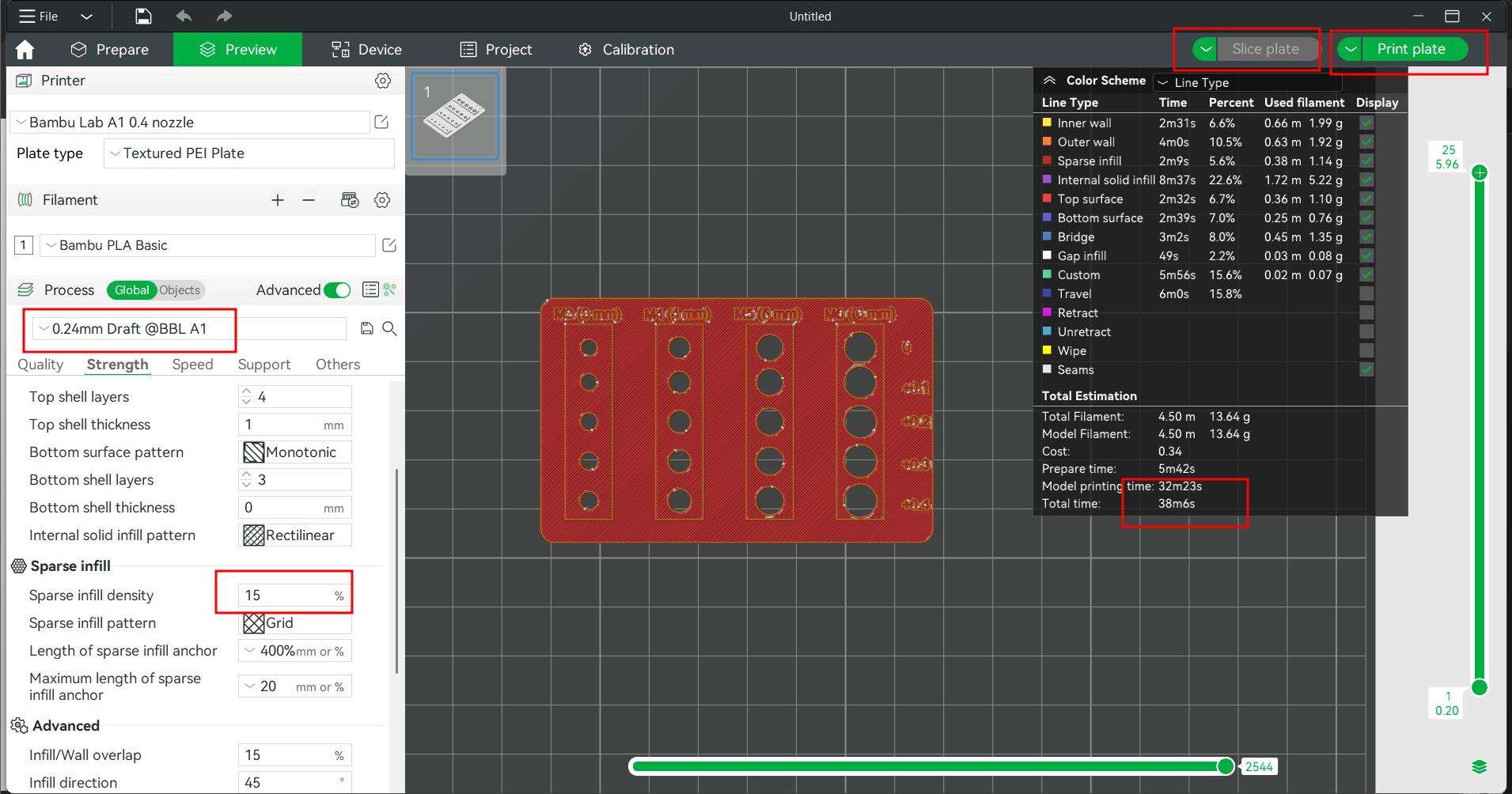
In bambu lab A1 printer the screw test model is printed. I sliced the plate and clicked on "Print Plate." Then, I selected "Send File," and the printer received the file and began printing the model.
Required clearance for screw holes
- M3 = + 0.3
- M4 = +0.2
- M5 = +0.3
- M6 = +0.1
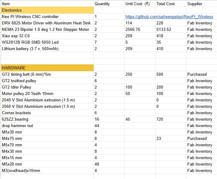
I were assigned with preparing the BOM, which I updated in the group assignment page.We wanted two 6mm GT2 belts, each of 5m length which wasn't available in the inventory. So we purchased it. M3x75mm screws were also purchased from outside. We used neo pi wireless CNC controller made by our instructor saheen palayi, that was available in the lab. As there was no corner brackets available in the inventory we took it from Saheen's small milling machine. Rest of the materials were available in fab inventory.
As there wasn't any individual task to complete, I worked with Ashish and Revi in firmware testing.
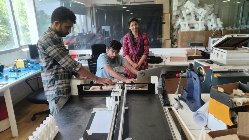
In an existing CNC plotter, the firmware was tested.
Firmware is a type of specialized software programmed into a hardware device to control its basic functions and operations. Unlike regular software that runs on operating systems, firmware works at a lower level, providing the essential instructions that enable the hardware to initialize, communicate with other devices, and perform specific tasks. It is typically stored in non-volatile memory such as ROM, flash memory, or EEPROM, which allows it to persist even when the device is powered off. Firmware is crucial for ensuring that electronic devices function correctly and efficiently, and it can often be updated to fix bugs, improve performance, or enhance security.
ESP32 Grbl is a CNC controller project that uses an ESP32 microcontroller to run a version of the open-source Grbl firmware, which is commonly used to control CNC machines. Unlike traditional Grbl setups that rely on wired connections and a dedicated computer, ESP32 Grbl offers enhanced functionality through built-in Wi-Fi, Bluetooth, and web interface support. This allows users to wirelessly send G-code commands, monitor operations, and control the CNC machine from a smartphone, tablet, or computer, making the system more flexible and convenient.
Using ESP-NOW protocol, we tested the motor rotation. Then core XY system was tested. We moved the end effector in positive and negative X and Y directions. After some effort , homing functionality was successfully tested. The overall concept was tested by sending G-codes.
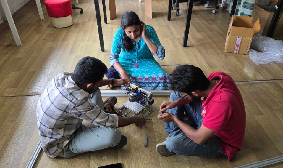
I helped Revi with assembling the machine.
This week helped me to understand about how machines work and how to build one.