Week 12 – Mechanical design, Machine design
This week is about making a machine that has mechanism, actuation, automation, function, and user interface.
The objective is to make machine that covers our previous learnings such as 2D and 3D design for creating machine mechanisms, input and output devices for actuation, electronics and coding for automation, function and user interface.
AI prompt ChatGPT: "can you give me an image by referring below two images, it was week 12 - Machine design week and we made a voice controlled smart rotary table. I am attaching the team photo (me, Ashthami, Ali, Ardra and Micheal) please include all in the image that you make. make the image fun animated and landscape image. we used 3D printer, CNC milling machine, leaser cutter, PCB milling machine. I am also attaching the final rotary table images."
Assignment Overview
- Design a machine that includes mechanism + actuation + automation + function + user interface
- Build the mechanical parts and operate it manually
- Actuate and automate your machine
- Document the group project and your individual contribution
- Document the individual contribution --> My main task was to design a mechanism of the group project and ensure the produced parts of mechanism are well integrated as assembly as per design.
| Day | Activity | Status |
|---|---|---|
| Thursday | Week Planning 📅, 2D Concept Sketching 📐 | Completed |
| Group Discussion, Brainstorming, Started 3D Modeling | Completed | |
| Friday | 3D Modeling and Understanding Mechanical Design | completed |
| Saturday | Rotary Mechanisms and 3D design 📐 | Completed |
| Sunday | Documentation 📝 | Completed |
| Monday | Rotary Mechanism - Redesigned with Improvements | Completed |
| Tuesday | Regional Review 👨🏫💬 | Completed |
| Wednesday | Started producing parts of mechanism | Completed |
| Group Documentation | Completed | |
| Individual Documentation | Completed |
Group Assignment
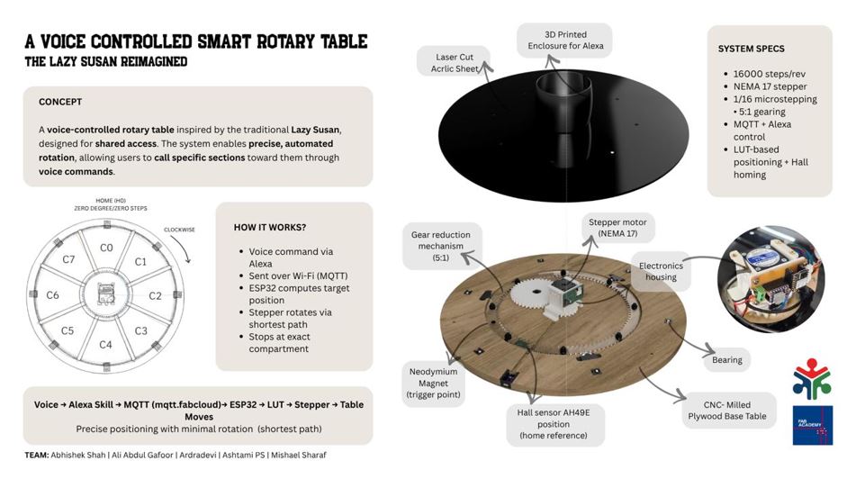
Our group project is centered around the idea of voice controlled rotary table. The primary idea is to use use it on dining table, however the system is designed as a multi-application propose such as organizing tools, holding art supplies, or managing shared resources in a workspace.
Individual Contribution
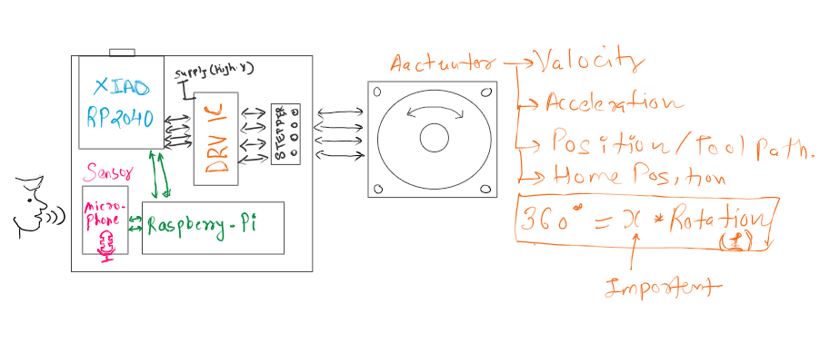
I had a responsibility to mechanism design, I chose the mechanical design because I wanted to strengthen my ability to think, design and build mechanism for my future projects. As I already have electrical background I chose the mechanical part of group work.
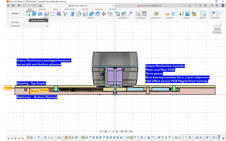
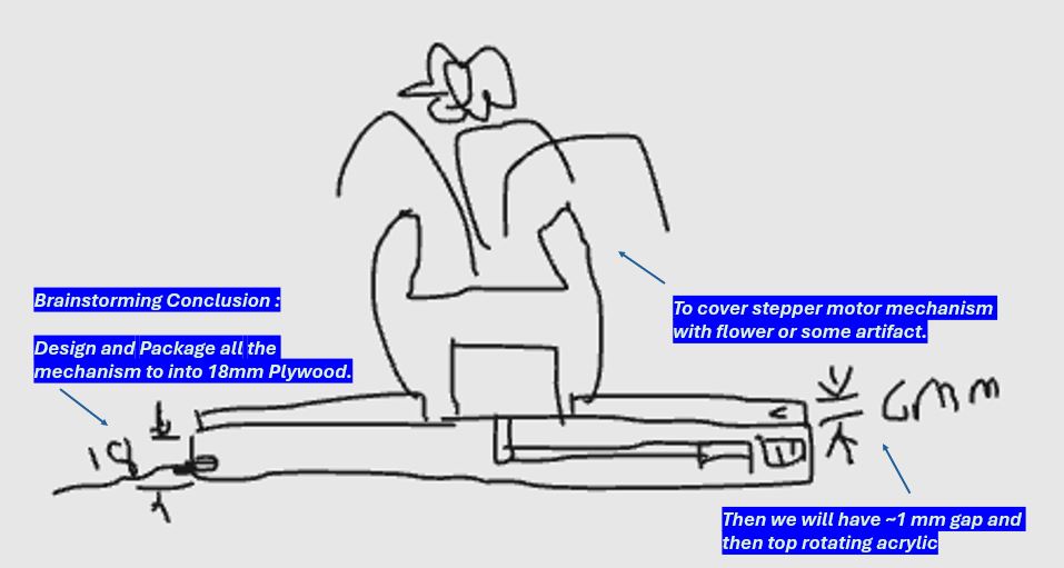
The challenge is to design a rotary mechanism that gets inside the 18mm plywood thus making rotary table look simple and slim. Therefore, making the complexity hidden behind the simplicity.
Below is the image and video of mechanism packaged inside the 18mm plywood.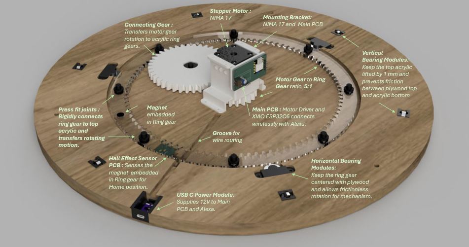
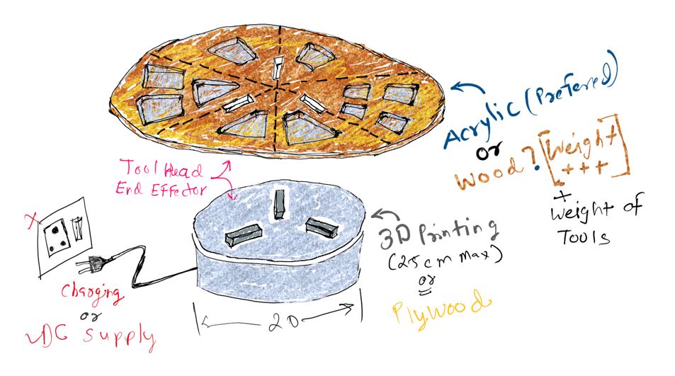
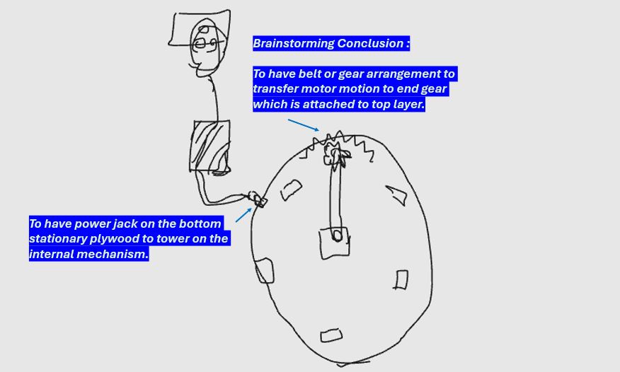
Sketching
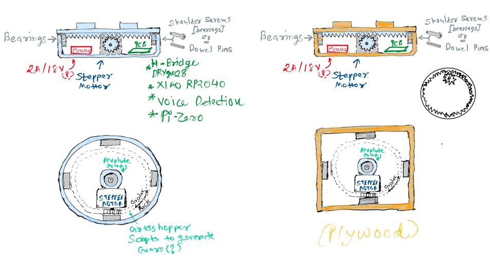
Before starting the CAD design, we explored several concepts through hand sketches. Sketching helped us quickly visualize different design possibilities, identify the major components, and understand how the mechanism would function. It also provided a simple way to communicate ideas with our instructors and teammates, gather feedback, and iterate on the design before investing time in detailed modeling.
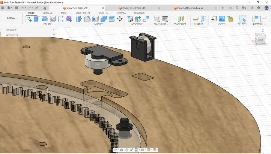
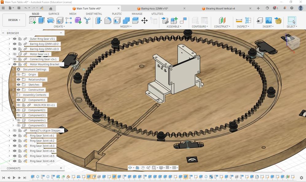
Hierarchical Assembly Structure
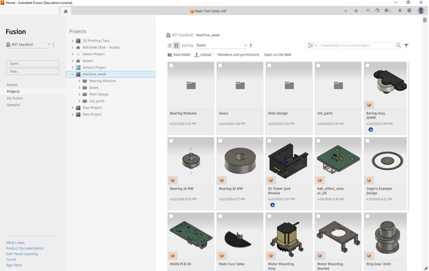
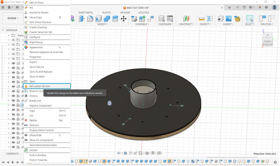
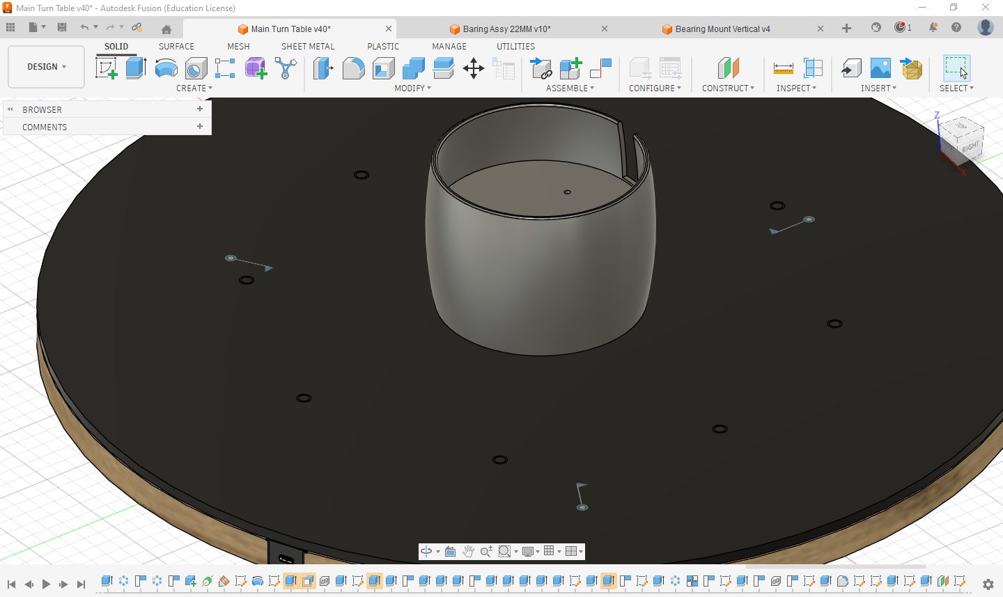
To manage the rotary table design efficiently, we adopted a Hierarchical Assembly Structure (HAS) approach in Fusion 360. Instead of creating all components within a single file, the design was divided into smaller sub-assemblies and individual components. This approach improved organization, simplified collaboration, and made design iterations easier to manage. Each major assembly could be developed independently while remaining linked to the main project.
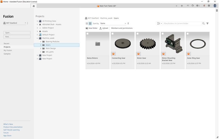
One of the major advantages of using a Hierarchical Assembly Structure is the ability to update components independently. If a component or sub-assembly is modified in its original design file, Fusion 360 can automatically synchronize the changes with the main assembly using the "Get Latest Version" function. This ensures that all team members work with the most up-to-date design while avoiding duplicate files and manual rework.
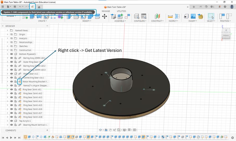
My Learning: Using a hierarchical assembly structure makes large projects easier to manage, especially when multiple people are working on different parts simultaneously. It improves design organization, reduces the risk of version conflicts, and allows design changes to be propagated throughout the assembly with minimal effort.
Base Structure (Bottom Plywood)
The bottom plywood plate serves as the primary structural foundation of the rotary table. It supports and aligns all major mechanical and electrical components while maintaining the overall rigidity of the assembly. In addition to acting as a mounting platform, it ensures that the relative positions of the components remain fixed during operation, which is essential for smooth and reliable motion.
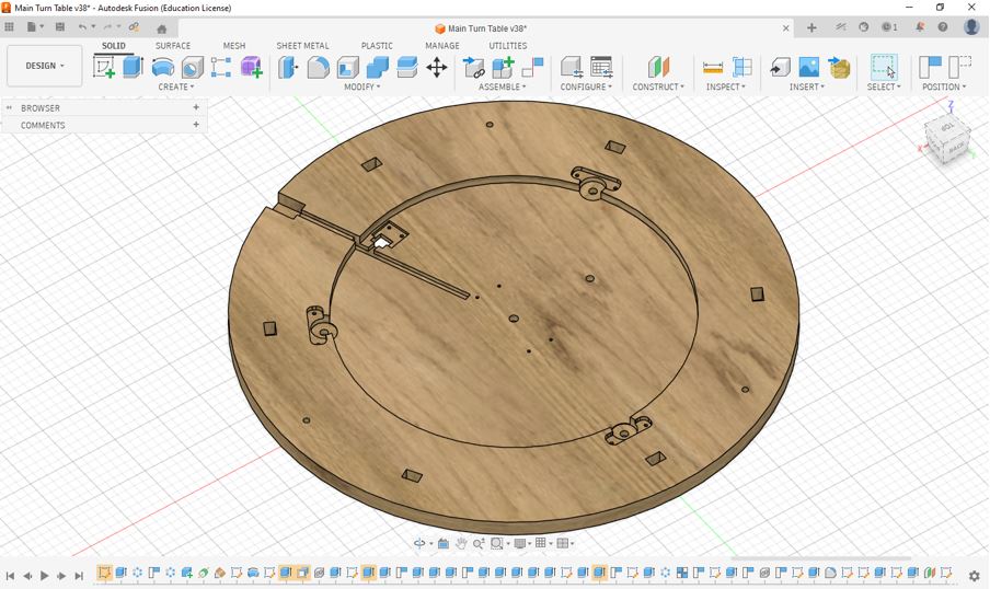
The base structure acts as the common interface for all major assemblies and mechanisms, including:
- Stepper motor mounting structure
- Gear transmission system
- Shaft and bearing supports for gears
- Electronic control hardware / Hall effect sensor IC
- Structural frames and fastening elements
My Learning: Initially, I considered the base plate as a simple supporting component. However, during the design process I realized that it plays a critical role in maintaining alignment, structural stability, and assembly accuracy. A well-designed base structure simplifies assembly, reduces positioning errors, and improves the overall reliability of the machine.
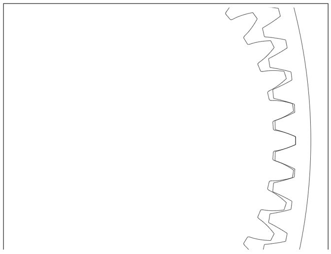
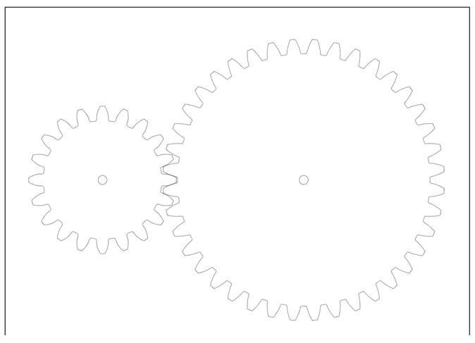
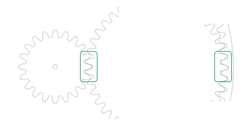
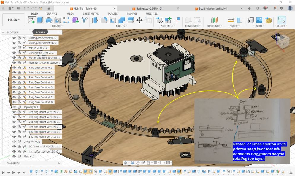
Gear Design and Transmission System
The gear mechanism was designed to transfer motion from the stepper motor to connecting gear and then to ring gear and finally to the rotary table top - while providing sufficient torque and precise speed control. Since the table is required to rotate smoothly under load, the gear train plays a critical role in determining the overall performance of the machine.
Based on our instructor's recommendation, the target was to achieve approximately a 20:1 or 15:1 gear reduction ratio. This means the motor gear would rotate approximately 15 times for every 1 revolution of the rotary table. Such a reduction ratio helps increase output torque while providing finer control over the table's angular movement.
One of the most important lessons from this design was understanding the effect of the gear reduction ratio. Initially, our instructor suggested targeting a 15:1 gear ratio, which would provide high torque and finer control of the rotary table. However, during the design process I mistakenly calculated and implemented a gear ratio closer to 5:1. As a result, the system produced less torque multiplication than expected.
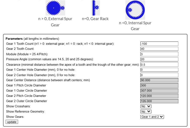
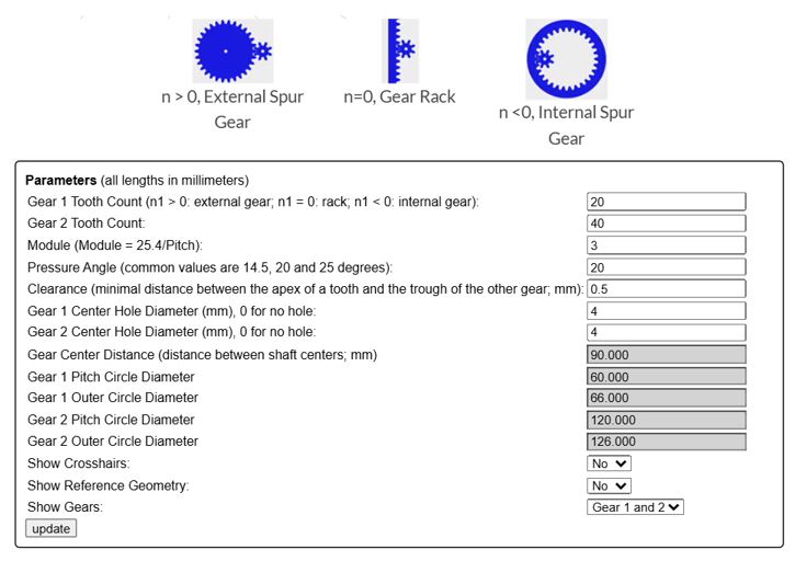
| Gear | Tooth Count | Pitch Circle Diameter (PCD) |
|---|---|---|
| Motor Gear (Pinion) | 20 | 60 mm |
| Connecting Gear | 40 | 120 mm |
| Ring Gear (Internal Gear) | -100 | 300 mm |
I used below - spur gear generator - tool to get the DXF of gears that I decided in above table.

Key Design Decisions
- Selected a gear-driven transmission system to achieve positive motion transfer without slippage.
- Used a large ring gear to increase output torque and improve rotational control.
- Designed the gear mechanism to be integrated directly with the rotary table structure.
- Prioritized smooth table rotation and accurate positioning over rotational speed.
- Optimized the gear placement to fit within the available assembly envelope.
Challenges and Learning
One of the most important lessons from this design was understanding the effect of the gear reduction ratio. Initially, our instructor suggested targeting a 20:1 gear ratio, which would provide high torque and finer control of the rotary table. However, during the design process I mistakenly calculated and implemented a gear ratio closer to 5:1. As a result, the system produced less torque multiplication than expected.
While the mechanism was still functional, the lower reduction ratio reduced the mechanical advantage of the gear train. This highlighted the importance of carefully validating gear calculations during the design phase, as even small mistakes in tooth count selection can significantly affect the performance of the final machine.
My Learning: Gear ratios directly influence the trade-off between speed and torque. A larger reduction ratio increases torque and positioning resolution, whereas a smaller reduction ratio results in faster motion but reduced torque. This exercise taught me the importance of verifying gear calculations early in the design process and understanding how design decisions impact the overall machine performance.
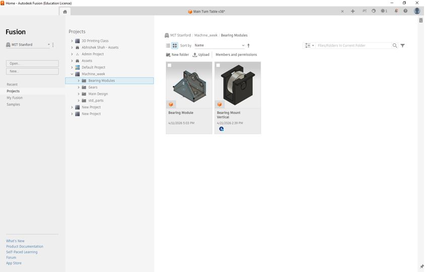
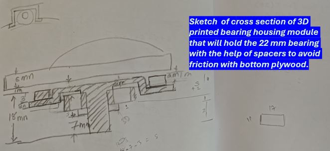
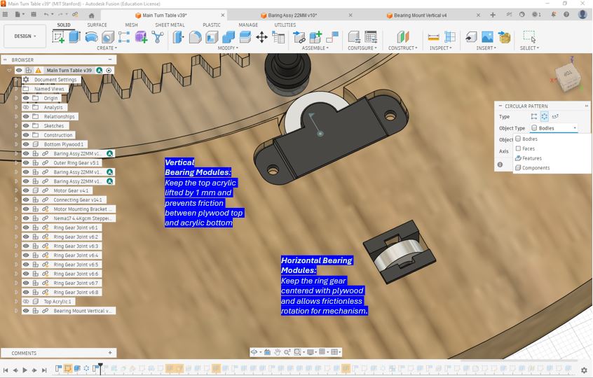
Bearing Modules
As part of the machine design study, I explored the construction and operation of bearing modules. Bearings are fundamental mechanical components used to support rotating shafts while minimizing friction between moving parts. By incorporating rolling elements between the Bottom wooden base and Top Acrylic, bearings enable smooth motion, and reduce wear in mechanical systems.
The bearing modules here support both radial and axial loads.
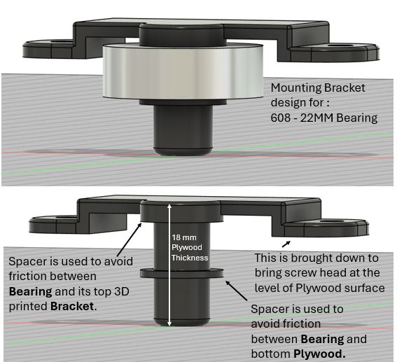
Key Observations
- Reduced Friction: Bearings significantly reduce friction compared to direct surface contact.
- Improved Efficiency: Less energy is lost due to friction, resulting in smoother operation.
- Load Support: Bearings are designed to support radial loads, axial loads, or a combination of both.
- Alignment: Bearing housings help maintain proper shaft alignment within a mechanism.
- Reliability: Properly selected bearings increase the lifespan and reliability of mechanical systems.
⚙️ Motor Mounting
A motor mounting bracket is a critical mechanical component used to securely attach a motor to a machine structure while maintaining proper alignment with the driven mechanism. A well-designed mounting system improves stability, reduces vibration, and ensures efficient transmission of torque from the motor to gears, pulleys, lead screws, or other motion systems.
During this exercise, I studied the design and construction of a motor mounting bracket and observed how it provides a rigid interface between the motor and the machine frame. Proper mounting is particularly important in machine design because even small alignment errors can lead to increased noise and reduced system performance.
📚 Key Design Considerations
- Structural Rigidity: The bracket must be sufficiently stiff to prevent unwanted movement during operation.
- Accurate Alignment: Proper alignment minimizes stress on shafts, bearings, and transmission components.
- Vibration Reduction: A secure mounting arrangement helps reduce vibration and improves machine stability.
- Ease of Assembly: Mounting holes and fastening features should allow straightforward installation and maintenance.
- Load Transfer: The bracket must safely transfer motor torque and reaction forces into the machine structure.
Acrylic Top and Motor/PCB Enclosure
To improve safety, protection, and overall appearance, an enclosure cover was incorporated into the machine design. The enclosure serves multiple purposes: protecting and covering the rotating motor components, preventing accidental contact with moving parts, and providing a dedicated space for housing the electronic control PCB and wiring.
The enclosure also helps organize cables and electronic components, resulting in a cleaner assembly and reducing the risk of wires interfering with the mechanical system. Integrating both mechanical and electronic elements within a single structure is an important aspect of machine design and system integration.
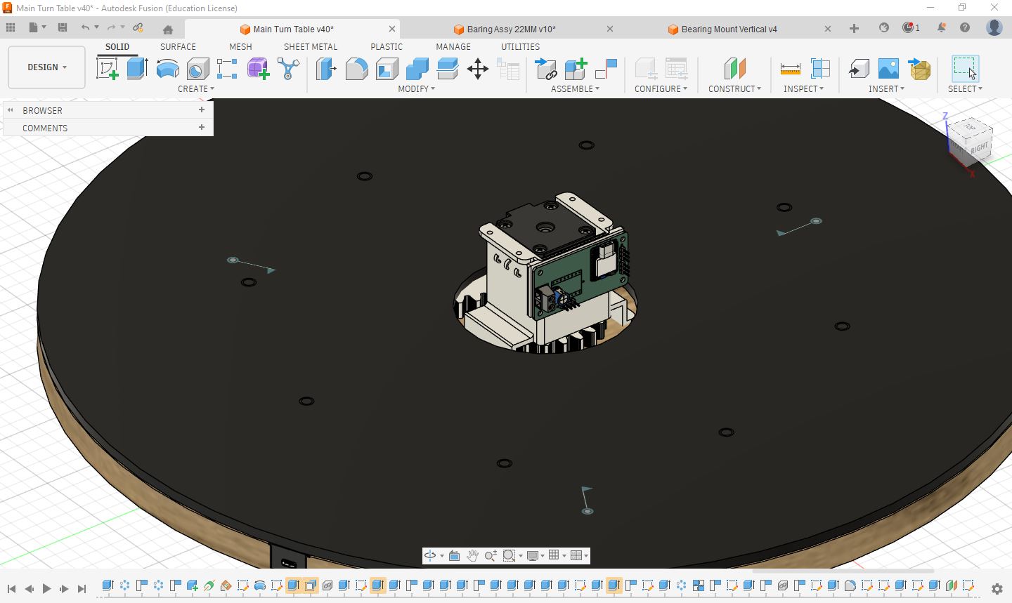
Key Design Considerations
- Safety: Prevents accidental contact with rotating shafts, gears, and motor components.
- Component Protection: Shields the electronics and mechanical parts from dust, debris, and accidental damage.
- Cable Management: Provides a dedicated space for routing and organizing wires.
- System Integration: Combines mechanical and electronic components into a single, organized assembly.
- Aesthetics: Improves the overall appearance and professionalism of the machine.
Learning
This exercise highlighted that machine design extends beyond motion mechanisms alone. Enclosures, covers, and protective structures are equally important because they improve safety, reliability, maintainability, and user experience while providing a finished and professional appearance to the final system.
Ease of Assembly
This design was developed with ease of assembly in mind. The acrylic top cover is connected to the ring gear using press-fit joints, allowing the two components to be assembled quickly without additional fasteners. The ring gear is kept concentric with the motor gear through three horizontally mounted bearings positioned at 120° intervals. Additionally, eight vertical bearings support the ring gear and acrylic assembly, maintaining a 1 mm clearance from the base to ensure smooth and low-friction rotation.
The following design features contribute to the ease of assembly:
- Press-Fit Joints: Provide a simple and rigid connection between the ring gear and the acrylic top cover.
- Three Horizontal Bearings (120° Apart): Maintain concentric alignment between the ring gear, acrylic top, and motor gear.
- Eight Vertical Bearings: Support the rotating assembly and maintain a 1 mm gap above the base for smooth rotation and reduced friction.
Hero Shot
Design file Downloads Links
- Entire Mechanism Download Here
- Bearing Assembly for Horizontal Stability Download Here
- Bearing Assembly for Vertical Stability Download Here
- Motor Mounting Bracket Download Here
- Motor Gear Download Here
- Connection Gear Download Here
- Ring Gear Download Here
Important Links
- We can get CAD files of standard parts from Grabcad.com
- Gear Design Tool Evolvent Design
- Standard Dimensions of bearings can be find here
- Useful Collaboration Tool Miro board