Design, build, and connect wired or wireless node(s) with network or bus addresses and a local input and/or output device(s).
Individual Assignment
This week I have to communicate between 2 boards. In the previous weeks input device week 9 and output device week 10 I had created 2 boards.
I am trying to create wireless connection between them. I have used ESP-NOW (Espressif Network Operation Wireless) and BLE (Bluetooth Low Energy).
Communication is the key... well, to everything I guess!?
So under everything comes Printed Circuit Boards too.!
Now, how do I make communication happen between these?
This communication between the board , other components or devices is called a PCB interface. It is based on how they connect and communicate with other boards or devices and exchange information with each other.
It could be via wires or wireless connections.
TO CREATE COMMUNICATION BETWEEN PCB BOARDS THERE ARE DIFFERENT WAYS.
These methods can be broadly divided into wired and wireless modes of communication.
Wired interface : Uses physical connections like cables, connectors, or traces on a PCB to transfer data, control signals, or power between devices.
Protocols like UART, I2C, and SPI use wired communication. These methods are generally reliable and fast, but the communication distance is limited by the physical connection. Wireless interfaces : These do not need physical connections to work. Data is transferred through radio waves, allowing devices to communicate without being directly connected.
Common wireless communication methods include Bluetooth, Wi-Fi, and LoRa. The choice depends on factors such as range, speed, and power consumption.
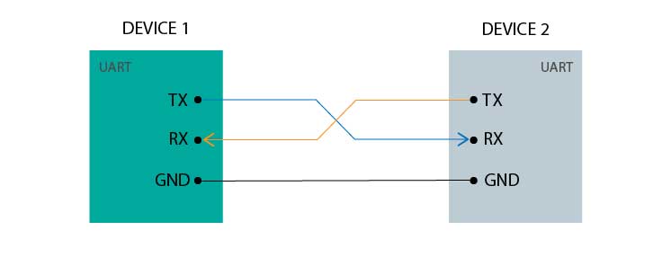
UART is one of the simplest communication protocols and is commonly used for communication between microcontrollers, sensors, computers, and other electronic devices. It transmits data bit by bit using an asynchronous serial communication protocol. Since it is asynchronous, there is no separate clock line shared between devices. For communication to work properly, both devices must be configured with the same baud rate (communication speed). Common baud rates include 9600, 115200, and others.
It uses a TX (Transmit) and RX (Receive) wire interface to transfer data. The data is usually sent as 7 or 8 data bits wrapped between a start bit (0) and a stop bit (1) for synchronization. RX of one board must be connected to TX of the other board, and vice versa.
Because only two signal wires are needed, UART is easy to set up and is often used for debugging, serial monitoring, and communication between two devices.The decent distance commnunciation can happen is under 2 meters, maximum distance is 15 meters with low baud rate. This is important when building products.
Serial Peripheral Interface (SPI)
This is used for high speed communication between microcontrollers and sensors. They need multiple wires. Good for short distance communications inside the boards.
Inter-Integrated Circuit (I2C)
In this communication, 2 wires allow multiple devices communication using the same wires. Each device has its own unique address. Data is transferred in byte size.
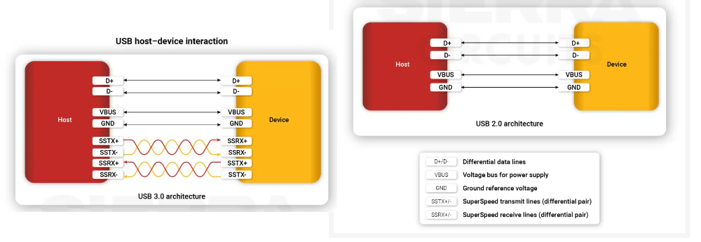
The wired mouse or the wired keyboard (peripherals) we connect to our computer, the phones we can plug and play with, while it transfers data and power.
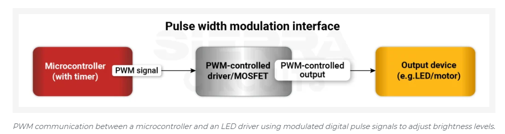
In simple terms, it is a technique to control the amount of power delivered to a device by turning the power on and off very quickly. Used in fading LEDs, speed control of motors, and heating elements.
Wireless Communications
Bluetooth
This is a short range network called a piconet. It includes the primary device and secondary devices that could directly speak to the primary device. Can cover up to 10 meters. This is why our Bluetooth earphones also say 10 meters connection. Low power consumption.
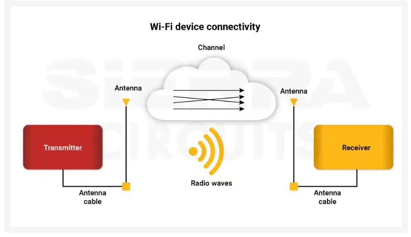
Enables devices to connect to local area networks and the internet using radio waves. This moves data fast over a medium distance. Consumes more power than Bluetooth.
Radio Frequency Identification (RFID)
This uses electromagnetic fields to read and write data from the devices. Used in tracking and access control. Access cards use them.
ESP-NOW is a wireless communication protocol developed by Espressif. It allows ESP devices to communicate directly with each other without the need for a Wi Fi router. It is fast, uses very little power, and devices can connect instantly using their MAC addresses. ESP-NOW can also work alongside Wi Fi and Bluetooth LE on supported ESP devices. It is a good choice for simple applications that need quick communication, such as smart home sensors, remote controls, and battery powered devices.
Breakout Board - KiCad
1 / 4
2 / 4
3 / 4
4 / 4
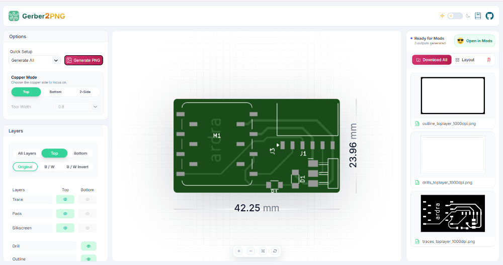
Gerber Files
The gerber files are downloaded and used to mill the PCB
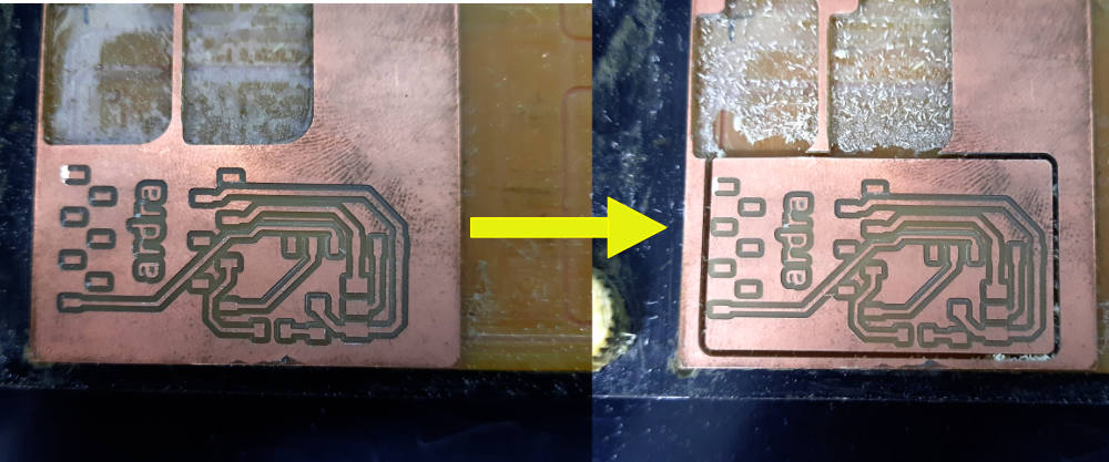
Milling PCB
1 / 4
2 / 4
3 / 4
4 / 4
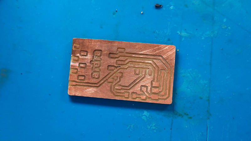
Soldered PCB
Previous week's boards
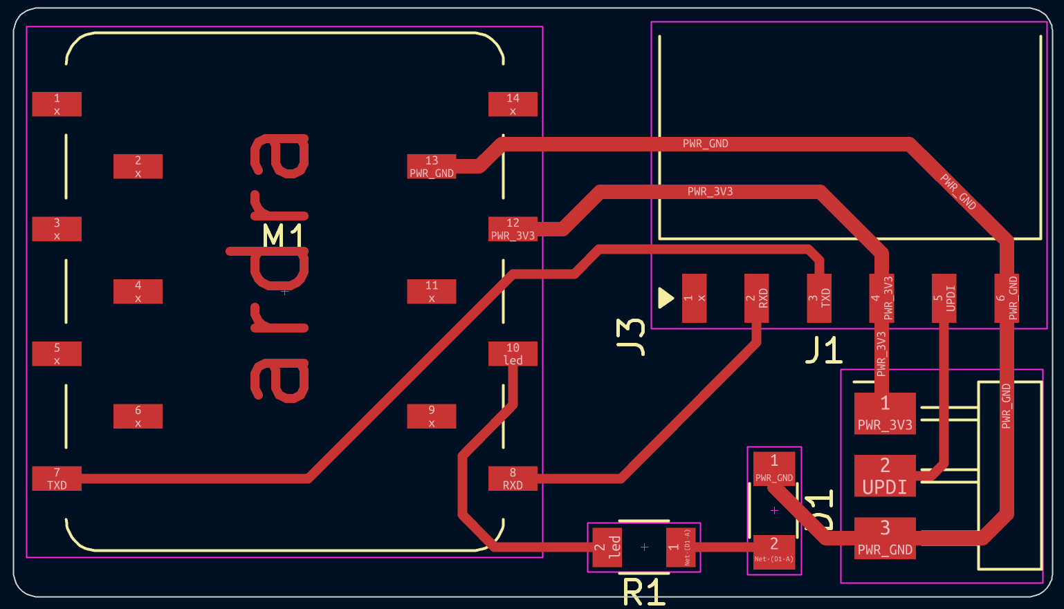
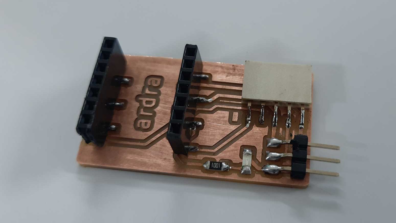
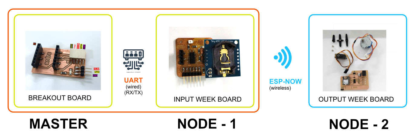
I had created two boards during the Input and Output Week. I wanted them to communicate with each other. The Input Week board has an ATtiny on it, and the Output Week board has a plug and play XIAO. To make it a system of three nodes, I am milling a breakout board with a plug and play XIAO on it.
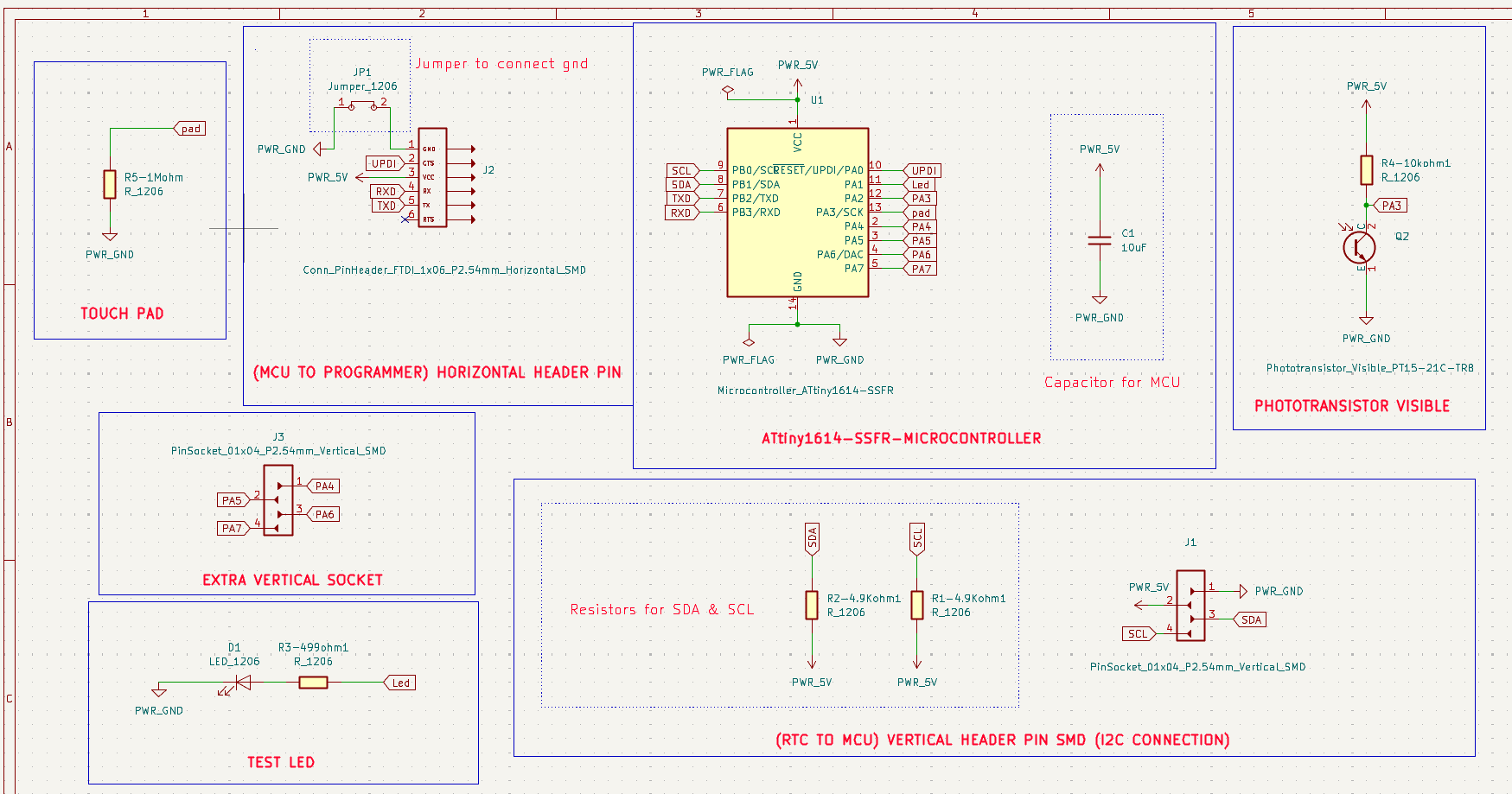
SCHEMATIC DIAGRAM - Input Week board with ATtiny 1614 Week-9
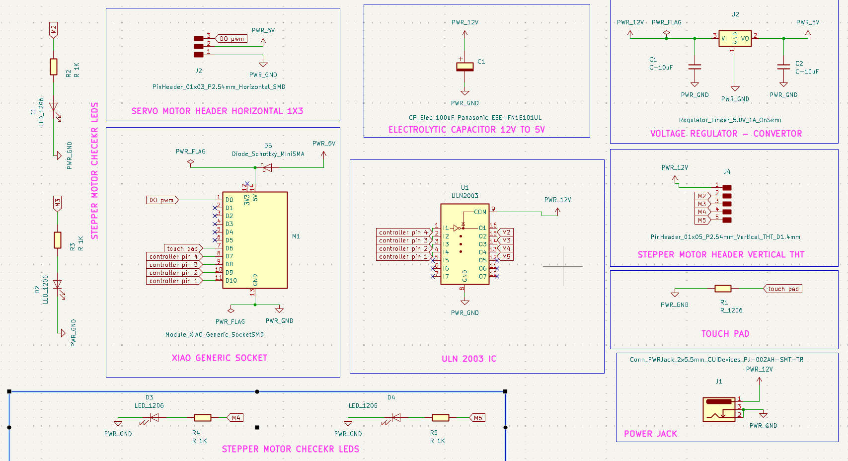
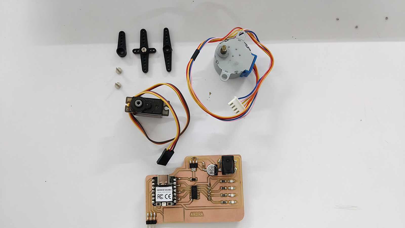
SCHEMATIC DIAGRAM - Output Week board with a plug and play XIAO RP2040 Week-10
Output Week board with a plug and play XIAO RP2040 Week-10
In the rest of the documentation I have mentioned NODE and MASTER. Apparently in ESP_NOW we dont have the concept of MASTER and NODE. I learnt this later as input from instructor Saheen. You can read more about it in Getting Started with ESP-NOW
System Overview
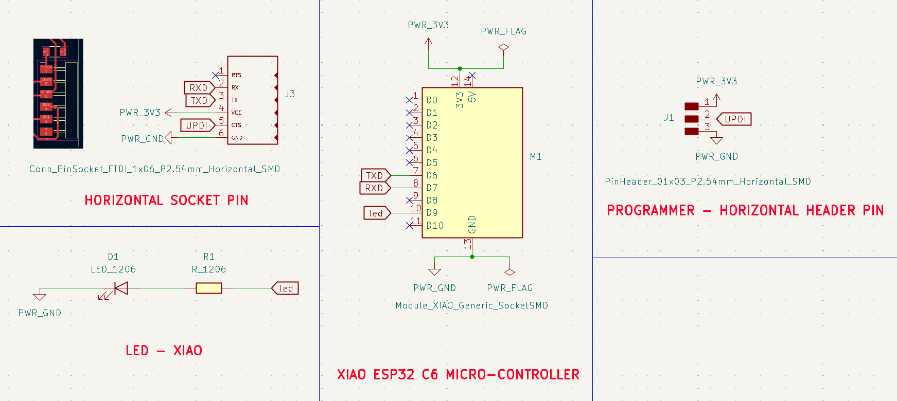
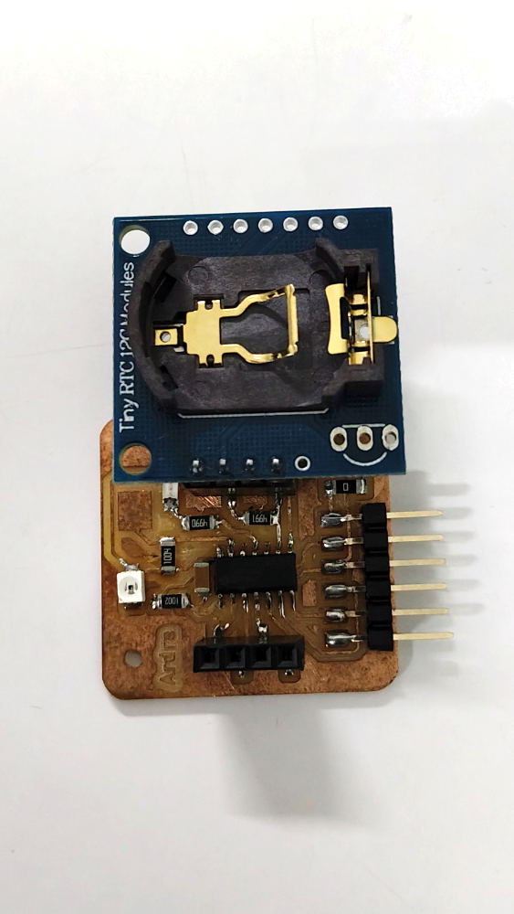
I created a breakout board to connect with my Week 9 input board. The Week 9 board uses an ATtiny1614 and includes an RTC, touch pad, and phototransistor. To add wireless communication, I connected a XIAO ESP32C6 to the ATtiny1614 through UART.
The XIAO ESP32C6 is used to send data wirelessly using the ESP NOW protocol. This allows the Week 9 input board to communicate with my Week 10 output board.
Why the RP2040 Would Not Have Worked for This Project
For this project, I needed two boards to exchange data wirelessly using ESP-NOW. The RP2040 cannot support ESP-NOW because it does not have built in Wi Fi or Bluetooth hardware. Adding wireless communication would require additional modules, which would increase both the circuit complexity and the board space required.
Since I used a plug and play approach by adding a developer board through headers, I had the flexibility to switch between different XIAO developer boards whenever needed. The Seeed Studio XIAO RP2040, ESP32-C6, and ESP32-S3 all share the same form factor, pin count, and pin pitch, making them interchangeable without redesigning the board.
The ESP32-C6 already includes Wi Fi, Bluetooth, and ESP-NOW support, allowing direct wireless communication between the boards without any additional hardware. This made it a much more suitable choice for the networking and communication requirements of the project.
Developer boards - Seeed Studio XIAO ESP32
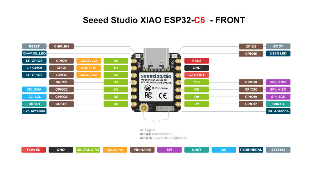
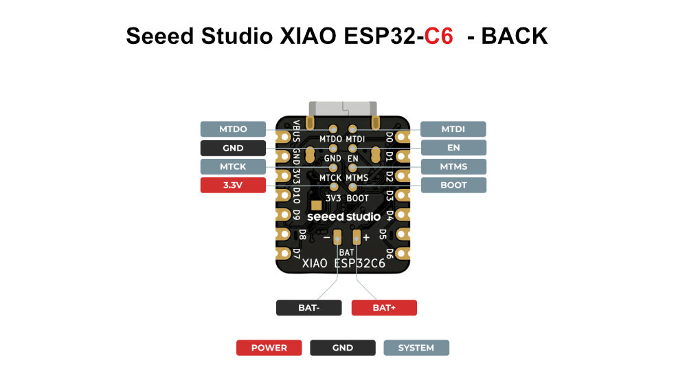
Seeed Studio XIAO ESP32-C6
The XIAO ESP32-C6 is a next generation wireless microcontroller built for modern IoT and smart home applications. It supports Wi Fi 6, Bluetooth 5.3, Thread, Zigbee, and Matter, making it ideal for devices that need to communicate across multiple wireless ecosystems while maintaining low power consumption. An IoT (Internet of Things) ecosystem is an interconnected network of physical devices embedded with sensors, software, and connectivity. It collects, shares, and acts on data automatically.
Seeed Studio XIAO ESP32-C6 - Pinout diagram Image source
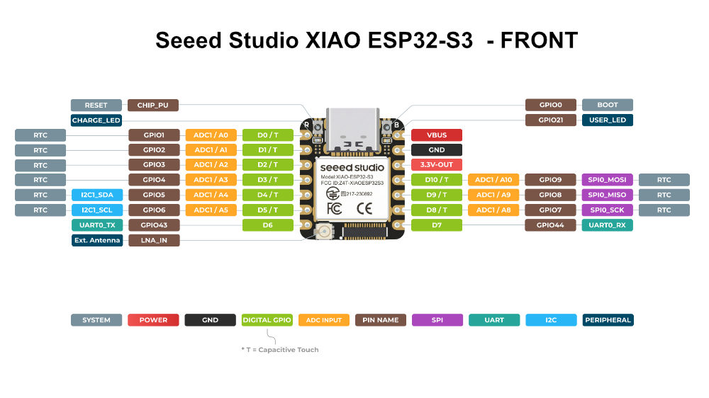
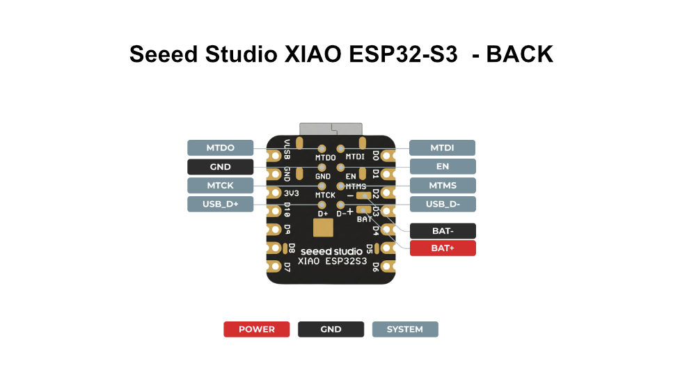
Seeed Studio XIAO ESP32-S3
The XIAO ESP32-S3 is a powerful microcontroller designed for projects that need higher processing performance. It is well suited for AI, machine learning, image processing, multimedia applications, and complex interactive projects. Its mature ecosystem and strong community support can also help reduce development time.
Seeed Studio XIAO ESP32-S3 - Pinout diagram Image source
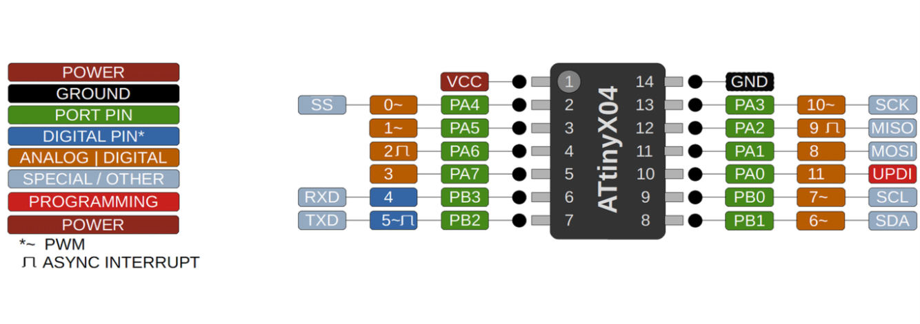
With all this said, does the unique specialty of these boards actually matter for my board? Actually, no. I have only used them for touch input, motor control, and getting the time from the RTC. So I have used the XIAO ESP32 boards interchangeably in my project.
At first, I thought that I was using BLE when communicating between the boards, but I later realized that I was only using ESP-NOW. I understood that much later. Learnings do happen after you have completed trying to make the board work.
Also, this is a lot to learn in one week. I mean, I am learning about communication protocols and different boards while also trying to complete the assignment. So it just means: do your assignment. Learning is a spiral thing. (Yeah you could get lost in it)
Lets follow some traditions
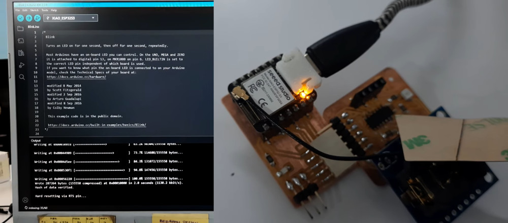
The blink test
Open:
File → Examples → 01.Basics → Blink
Code explained
LED_BUILTIN – The LED on the board. LED_BUILTIN is used in the code for Arduino to understand which onboard LED should be controlled. The developer board connected is selected from the board list. The board definition files specify which GPIO pin the onboard LED is connected to. During compilation, LED_BUILTIN is replaced with the GPIO number defined for that board. For the Seeed XIAO RP2040, this is GPIO 25. This GPIO number is what the microcontroller understands. Therefore, when the code writes to GPIO 25, the onboard LED connected to GPIO 25 blinks.
pinMode(LED_BUILTIN, OUTPUT); – Sets the LED's pin as OUTPUT
digitalWrite() – Inside this we define what action it has to do
digitalWrite(LED_BUILTIN, HIGH); – This defines that the LED is HIGH or ON
delay(1000) – 1000 milliseconds, that is a 1 second delay in performing the next action
How much can a person forget in 1 week?
I heard about UART, and I plugged the breakout board into the ATtiny1614 board using the UART pins. I was trying to program the Microchip ATtiny1614 through the Seeed Studio XIAO ESP32C6. I thought that since these pins were connected, the XIAO ESP32C6 would be able to tell the ATtiny1614 what to do. It turns out that it does not work that way. It still needs the programmer I used in Week 9. So there I was, spending time on something that did not work. I had to be reminded by my instructor to use the programmer.
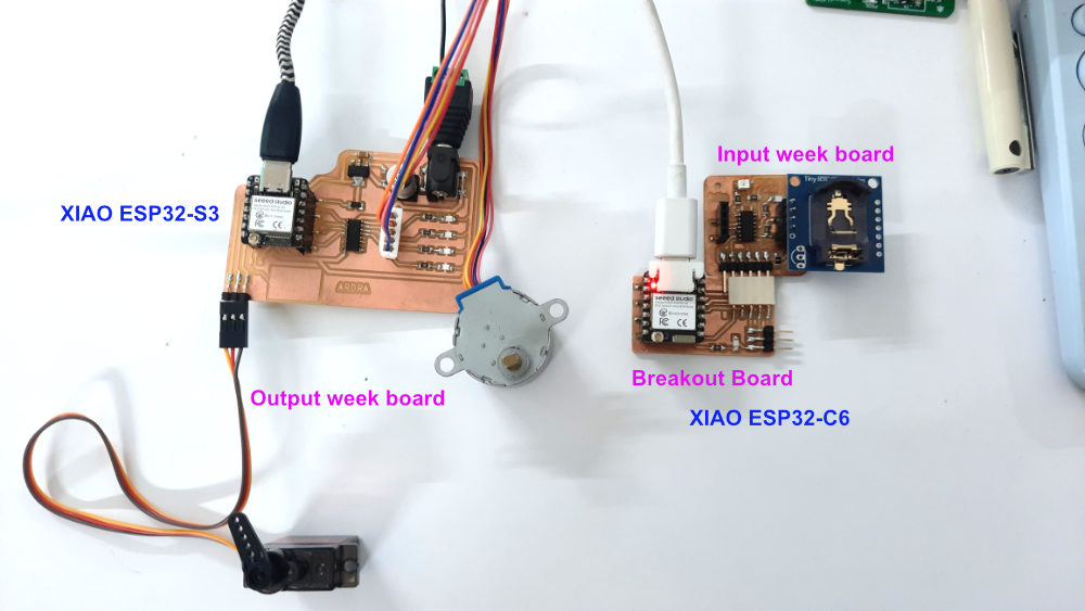
After that, every time I used the programmer to program the Microchip ATtiny1614. Then I connected the ATtiny1614 board to the breakout board with the Seeed Studio XIAO ESP32C6. Then I uploaded the program to the XIAO ESP32C6, followed by the code for the Seeed Studio XIAO ESP32S3 on the output week board, and communicated between these boards using ESP-NOW.
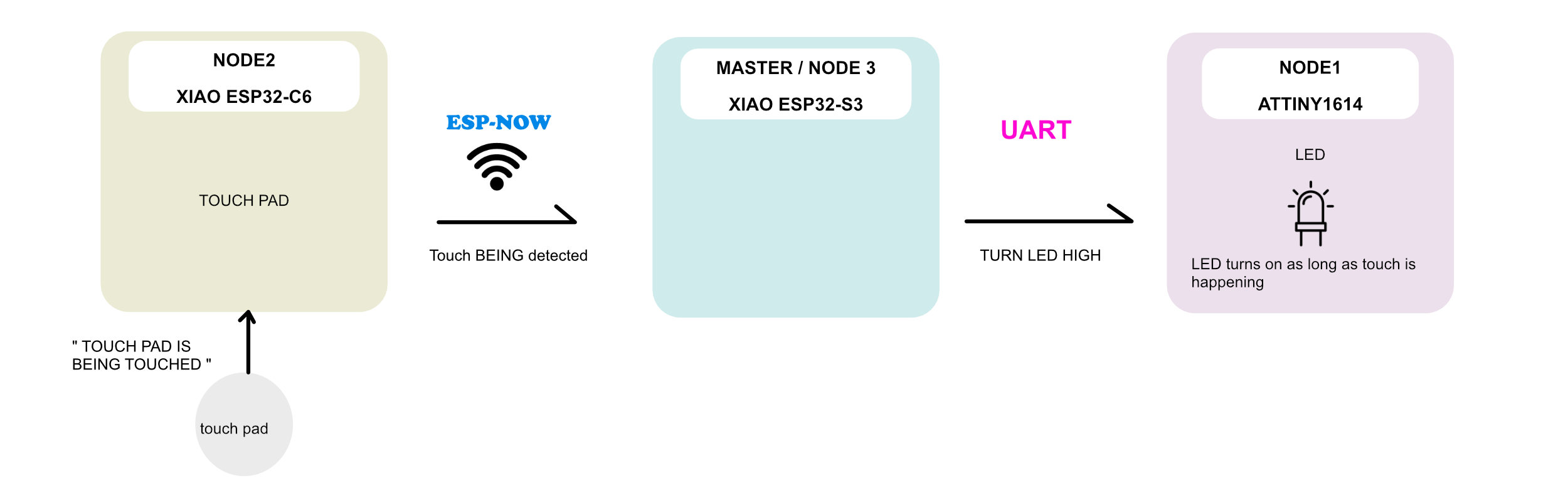
ESP-NOW : TOUCH + LED (half connection)
NOTE: Node 2 communicates to node 1 through node 3. This only completes a partial requirement for the assignment.
board2, breakout board, board1
I am trying to communicate between two microcontrollers using Arduino.
Board 1 which is the sender is seeed xiao esp32c6, this is connected on a breakout board connected to a PCB which has ATttiny1614, one led, touch pad and rtc.board 2: this has xiao esp32s3, which is connected to a servo and stepper motor.use ESP-NOW protocol to communicate via Bluetooth.Guide to through the steps. Use minimal words.I need to the led to light up when I touch the touch pad in board 1. This lets me know the touchpad is activated. When this happens I need the servo motor in board 2 to do 1 full rotation (180 degree).when I double tap on the touchpad in board 1, I need the stepper motor in board 2 to turn 1 step.create Arduino codes for it.
guide me step by step with simple short explanation
An LED is connected to PA3. I want it to be turned on when the touch pad is touched on Node 2. This uses ESP-NOW communication between Node 2 with the XIAO ESP32-C6 and the NODE 3/master with the XIAO ESP32-S3.
When I touch the touch pad on Node 2 with the XIAO ESP32-C6, I need it to communicate via ESP-NOW with the NODE2/master, which uses a XIAO ESP32-S3. An LED is connected to PA3 on the ATtiny Node 1 and should turn on.
What happened in this is that NODE 2 puts the input and the output was seen in NODE 2 with MASTER communciating. We also need communciation from node 2 to node 1 this is misisng.
Communcaition interface :NODE 2 > ESP-NOW > NODE3/MASTER and Communcaition interface : MASTER > UART > NODE 1.
ESP-NOW : TOUCH + LED AND PHOTOTRANSISTOR + SERVO
NOTE :The communication couldn't be completed. The touch pad was connected to D6 on the XIAO ESP32S3, and it didn't work as D6 didn't have capacitive touch.
The assignment is to complete two way communication using the same interface, which in my case is ESP NOW. This time, I am communicating between NODE 1 and NODE 2 over ESP NOW with MASTER.
Communication path 1: MASTER > ESP NOW > NODE 2
Communication path 2: MASTER > UART > NODE 1
    Arduino IDE with ESP32 board package version 3.3.7.
ESP-NOW communication
MASTER: XIAO ESP32C6 , NODE 1: ATTINY1614 , NODE2: XIAO ESP32S3
NODE 1: ATTINY1614
PA1 : LED-A
* LED_PIN, HIGH);  // LED ON
* LED_PIN, LOW);   // LED OFF
PA2 : PHOTOTRANSISTOR
* lightValue 0 = dark, 1023 = bright
 *(lightValue < 200 ) DARK
 *(lightValue < 600) DIM
send to MASTER (ESP32C6)  via UART
PB2 : TX , PB3 : RX

NODE2: XIAO ESP32S3
D0 : microServo MG90S
*Standard servos move 0-180.
D6 : TOUCHPAD-N
* Receive ESP-NOW data
* const int TOUCH_THRESHOLD = 20000;
 if (touchValue < TOUCH_THRESHOLD) {
    Serial.print("Touch Detected! Value: ");

MASTER (ESP32C6):
UART connection to NODE1
D6 : TX
D7 : RX
D9 : LED-N
* TRUE turns LED ON
* FALSE turns LED OFF

CONDITIONS
Master connected to node 1 via UART. MATER to NODE 2 via ESP-NOW
action 1 - WHEN “Touch Detected “ IN TOUCHPAD-N  on NODE 2  , LED-A becomes LED_PIN, HIGH on NODE-1.
action 2 - When  PA2 : PHOTOTRANSISTOR light value is “DARK” , D0 : microServo MG90S on NODE 2 does 180degree sweep once.
When either one of these actions are complete on “D9 : LED-N” BLINKS TWICE with delay500 miliseconds on MASTER

Important:
* Code must compile without errors
* Use correct ESP-NOW callback signatures for version 3.3.7
* Do not include unnecessary code
* Keep CODES separate
* Keep the code simple and beginner friendly

GENERATE CODES IN THIS ORDER
code 1 : mac address
code 2: NODE-1 ATTINY1615
code 3: MASTER ESP32-C6
code 4: NODE-2 ESP32-S3
 GENERATE 1 CODE THEN TROUBLESHOOT ADN THEN WILL ASK FOR THE ENXT CODE
CODE 1 : MAC ADDRESS OF NODE 2
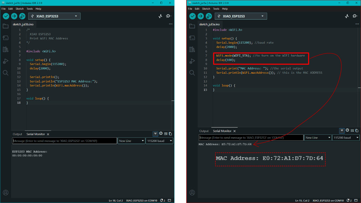
First step is to get the MAC address of Node 2. A MAC address is stored in the ESP32's WiFi system. Because it was not enabled, the first code didn't give me the MAC address. With WiFi.mode(WIFI_STA); it turned on teh WiFi Hardware
#include <WiFi.h>

void setup() {
  Serial.begin(115200); //baud rate
  delay(2000);

  WiFi.mode(WIFI_STA); //to turn on the WIFI hardware
  delay(100);

  Serial.print("MAC Address: "); //the serial output
  Serial.println(WiFi.macAddress()); // this is the MAC ADDRESS
}

void loop() {
}
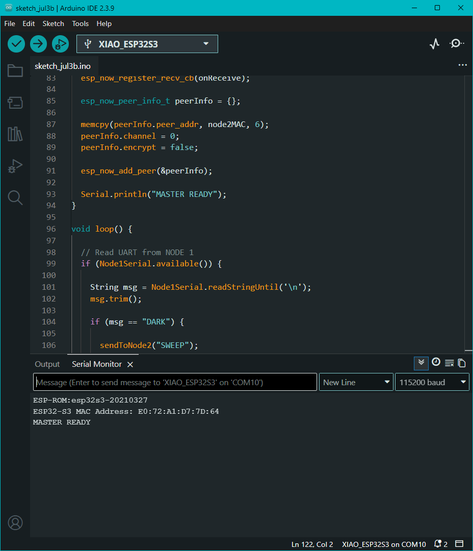
The first time the WiFi hardware was off. The next code included the function to turn on the WiFi. The MAC address of XIAO ESP32-S3 is E0:72:A1:D7:7D:64 as shown in the serial monitor with baud rate 115200
CODE 2 : NODE 1 - ATTINY1614
/*
  NODE 1 - ATTINY1614

  PA1 -> LED-A
  PA2 -> Phototransistor

  PB2 -> TX
  PB3 -> RX
*/

const byte LED_PIN = PIN_PA1; //LED-A
const byte LIGHT_PIN = PIN_PA2; // Phototransistor

String rxBuffer = "";  //string is a variable that can store data received from UART or any
bool darkSent = false; //this is a check box, if something is sent-true, not done-false

void setup() {

  pinMode(LED_PIN, OUTPUT); // led would be turnd on if pressed
  digitalWrite(LED_PIN, LOW);

  Serial0.begin(9600); //baud rate

  Serial0.println("NODE1 READY"); // after upload - seral print
}

void loop() {

  int lightValue = analogRead(LIGHT_PIN); // setting Phototransistor pin value conditons

  if (lightValue < 200) { //condition if Phototransistor read value lower then 200 then

    if (!darkSent) {

      Serial0.print("DARK "); //print value dark if vlaue less than 200
      Serial0.println(lightValue); //serial monitor pritns ligth avlue

      darkSent = true; // if value lower than 200 check the check box
    }

  } else {

    darkSent = false; //if not dont check the box
  }

  while (Serial0.available()) {

    char c = Serial0.read();

    if (c == '\n' || c == '\r') {

      if (rxBuffer == "LED_ON") { // if the rxbuffer gets "touch detected" input from node2

        digitalWrite(LED_PIN, HIGH); //turn led on

        Serial0.println("LED ON"); //serial monitor led on
      }

      else if (rxBuffer == "LED_OFF") { // if the condition not satisfied, led off

        digitalWrite(LED_PIN, LOW); //LED off

        Serial0.println("LED OFF"); //serial monitor reads led off
      }

      rxBuffer = ""; //if the node 2 input is received

    } else {

      rxBuffer += c; //if the node 2 input is not received
    }
  }

  delay(100);
}
Errors, errors, errors!! Things to keep in mind:
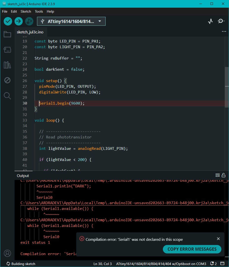
There was an error in uploading because Serial1. given in the first code was flagged by the program. Then it suggested to use Serial0.
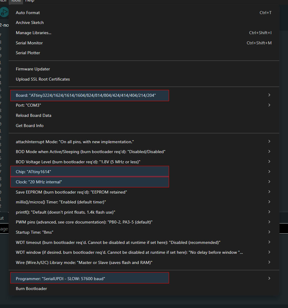
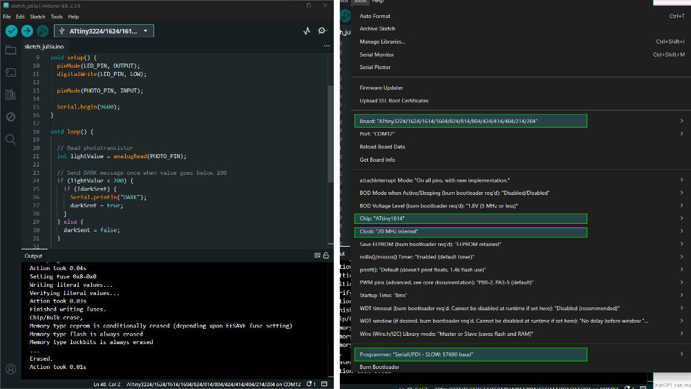
This is the board setup one needs to follow. I kept on running into errors because either one was changed. First of all, I used a Porsch Paste SMART UPDI programmer. Since it's a smart UPDI programmer, "Optiboot" was not needed. I changed the board from “ATtiny1614…w/Optiboot” to “ATtiny3224/1624/1614…”. On choosing the board “ATtiny3224/1624/1614…”, the chip changed to ATtiny3224 and it gave an uploading error, so I changed that to ATtiny1614. The clock speed had to be this, and the programmer was also changed.
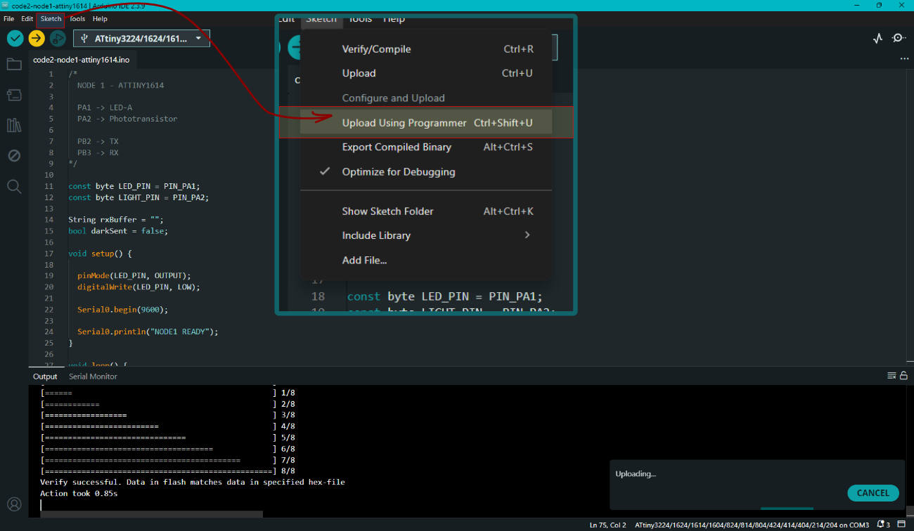
Here, even after the previous changes in settings, I faced an error in uploading. So ChatGPT suggested to upload by either selecting from SKETCH > UPLOAD USING PROGRAMMER or using Ctrl+Shift+U. Then the uploading worked.
#include  //wifi
#include  //esp now library

// UART to ATTINY1614
#define RX_PIN D7
#define TX_PIN D6 // pins UART

// Status LED
#define LED_N D9 //led on master

HardwareSerial Node1Serial(1); //uart conenction

// NODE2 MAC
uint8_t node2MAC[] = {0xE0, 0x72, 0xA1, 0xD7, 0x7D, 0x64}; //enter the MAC address

String rxBuffer = ""; //an empty text box that keeps incoming data from node 2

// ESP-NOW message
typedef struct {
  char text[16]; //this is the  text message sthat the string rx buffer box can hold
} Message;

Message msg; //Creates a message object named msg.It is the actual container used to send or receive text.

// --------------------
// Blink Master LED
// --------------------
void blinkTwice() {

  for (int i = 0; i < 2; i++) {

    digitalWrite(LED_N, HIGH); //led on
    delay(500); //delay of .5seconds

    digitalWrite(LED_N, LOW); //led off
    delay(500); //delay of .5seconds
  }
}

// --------------------
// ESP-NOW Receive
// ESP32 package 3.3.7
// --------------------
void onReceive(const esp_now_recv_info_t *info, //the input received from node 1 or node 2
               const uint8_t *data,
               int len) {

  Message incoming;

  memcpy(&incoming, data, sizeof(incoming));

  if (strcmp(incoming.text, "TOUCH") == 0) {

    Node1Serial.println("LED_ON");

    blinkTwice();
  }
}

void setup() {

  Serial.begin(115200);  //baud rate

  pinMode(LED_N, OUTPUT); //led is output
  digitalWrite(LED_N, LOW); //led is off

  Node1Serial.begin(9600, SERIAL_8N1, RX_PIN, TX_PIN);

  WiFi.mode(WIFI_STA); //wifi hardware is on

  if (esp_now_init() != ESP_OK) {  //id esp conenction is fine
    Serial.println("ESP-NOW Init Failed");
    return;
  }

  esp_now_register_recv_cb(onReceive); //run onReceive function when message arrives in ESP-NOW

  esp_now_peer_info_t peerInfo = {}; //stores info of the other board

  memcpy(peerInfo.peer_addr, node2MAC, 6); //Stores NODE 2's address so it knows where to send messages

  peerInfo.channel = 0; //if this is the condition
  peerInfo.encrypt = false; //no encryption

  esp_now_add_peer(&peerInfo);

  Serial.println("MASTER READY"); //serial print
}

void loop() {

  while (Node1Serial.available()) {

    char c = Node1Serial.read();

    if (c == '\n' || c == '\r') {

      if (rxBuffer == "DARK") { //if phototranssitor is dark

        strcpy(msg.text, "SWEEP"); // if "DARK" then 180 degree sweep

        esp_now_send(node2MAC,
                     (uint8_t *)&msg,
                     sizeof(msg));

        blinkTwice(); //to do blink function
      }

      rxBuffer = "";

    } else {

      rxBuffer += c;
    }
  }
}
Learnt the lesson of how important it is to notice the pinout diagram and understand it. XIAO ESP32S3 has touch capability on pins D0 to D5, and D8 to D10. Guess which pin I had my touch pad connected to? D6, which does not have capacitive touch. So now I have to exchange the XIAOs.
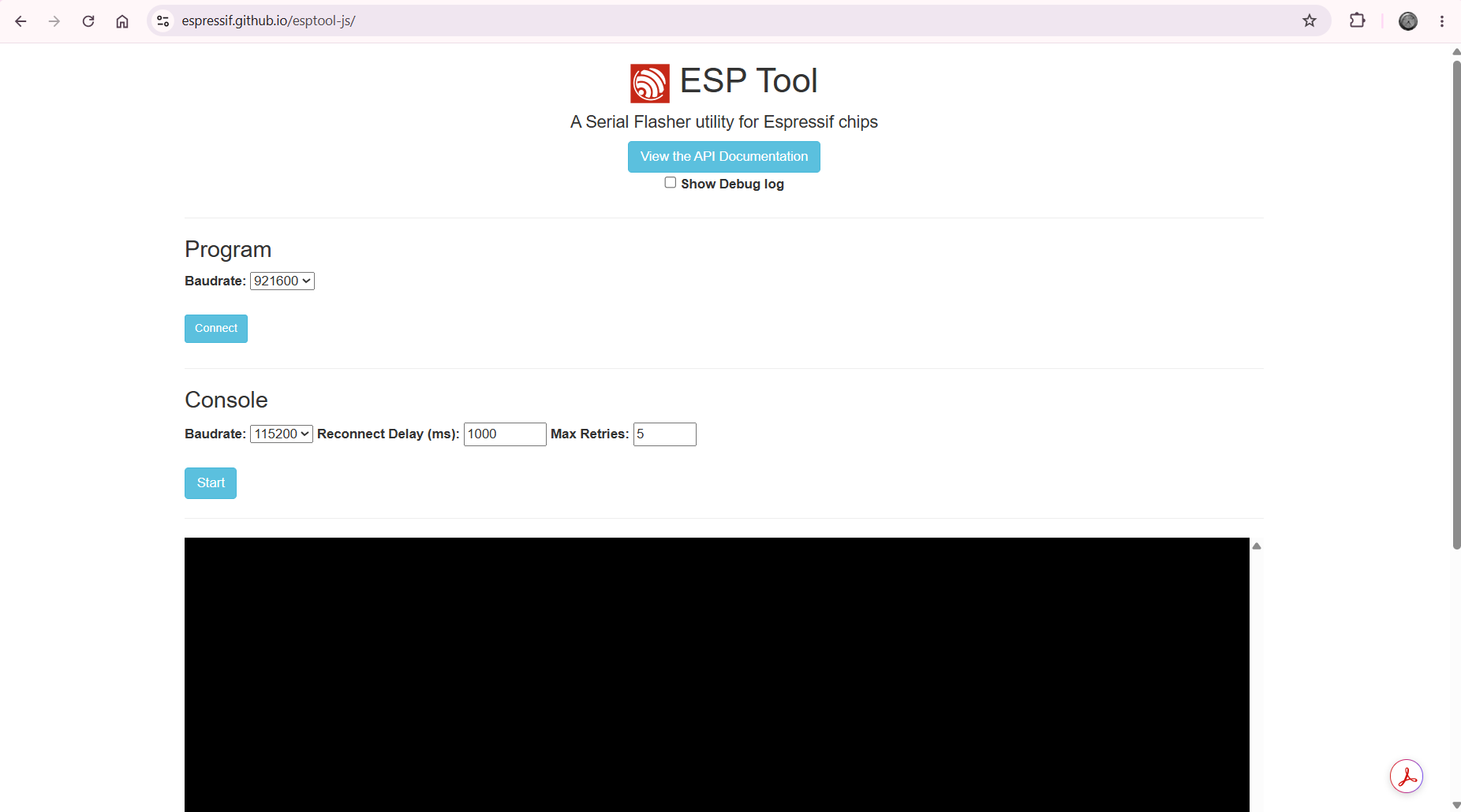
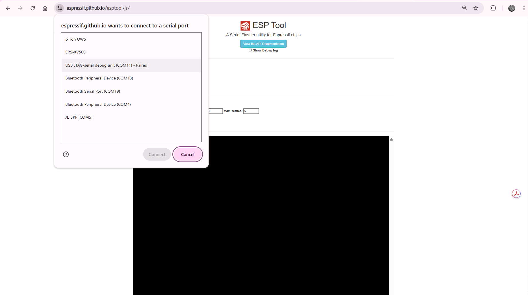
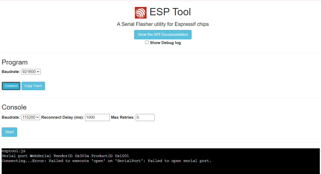
Troubleshooting - ESP TOOL
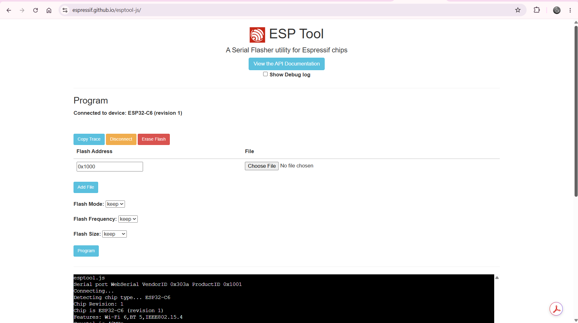
While working on this assignment, I used another XIAO ESP32 S3 and XIAO ESP32 C6. When I tried uploading the code, the upload repeatedly failed and displayed an error. Resetting the boards did not solve the issue. Instructor Saheen introduced me to the ESP Tool. This web tool detects the connected ESP board and allows the flash memory to be erased before uploading new firmware.
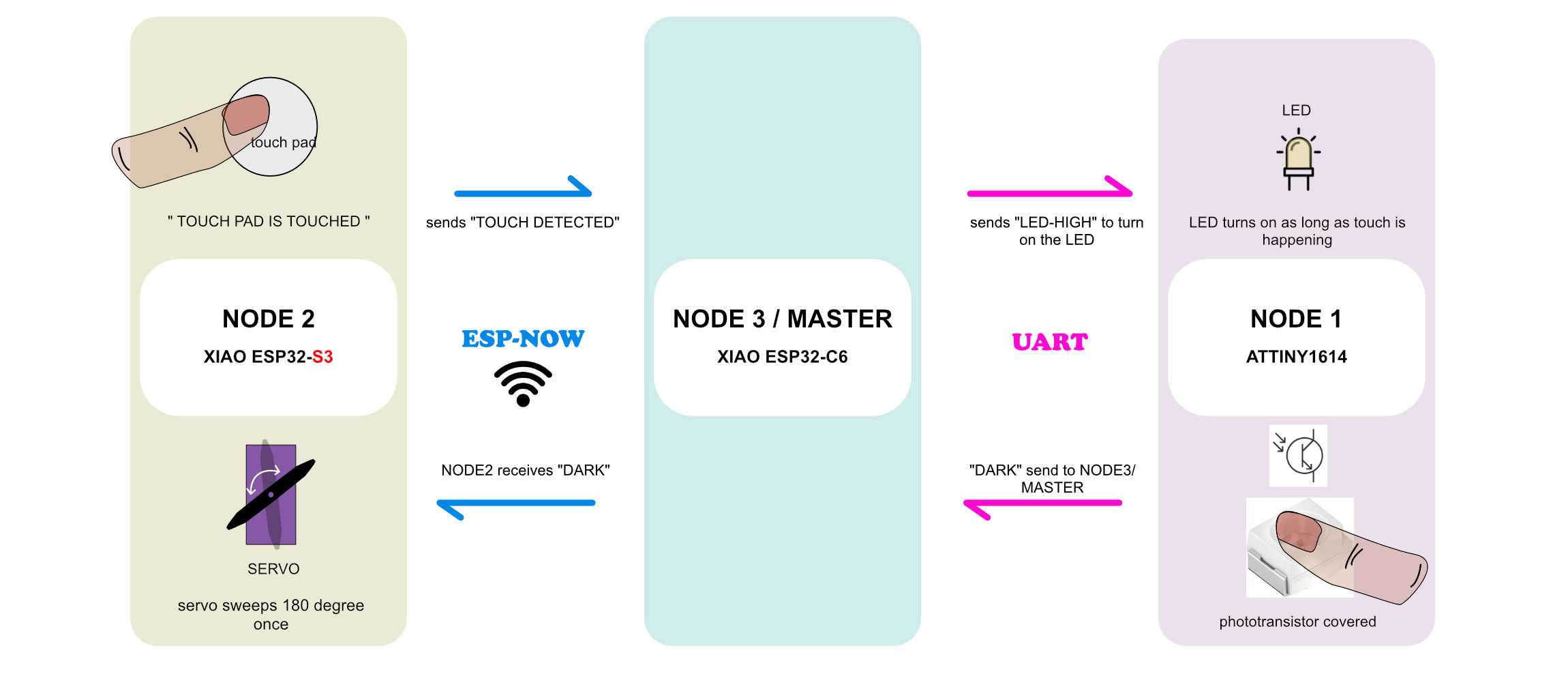
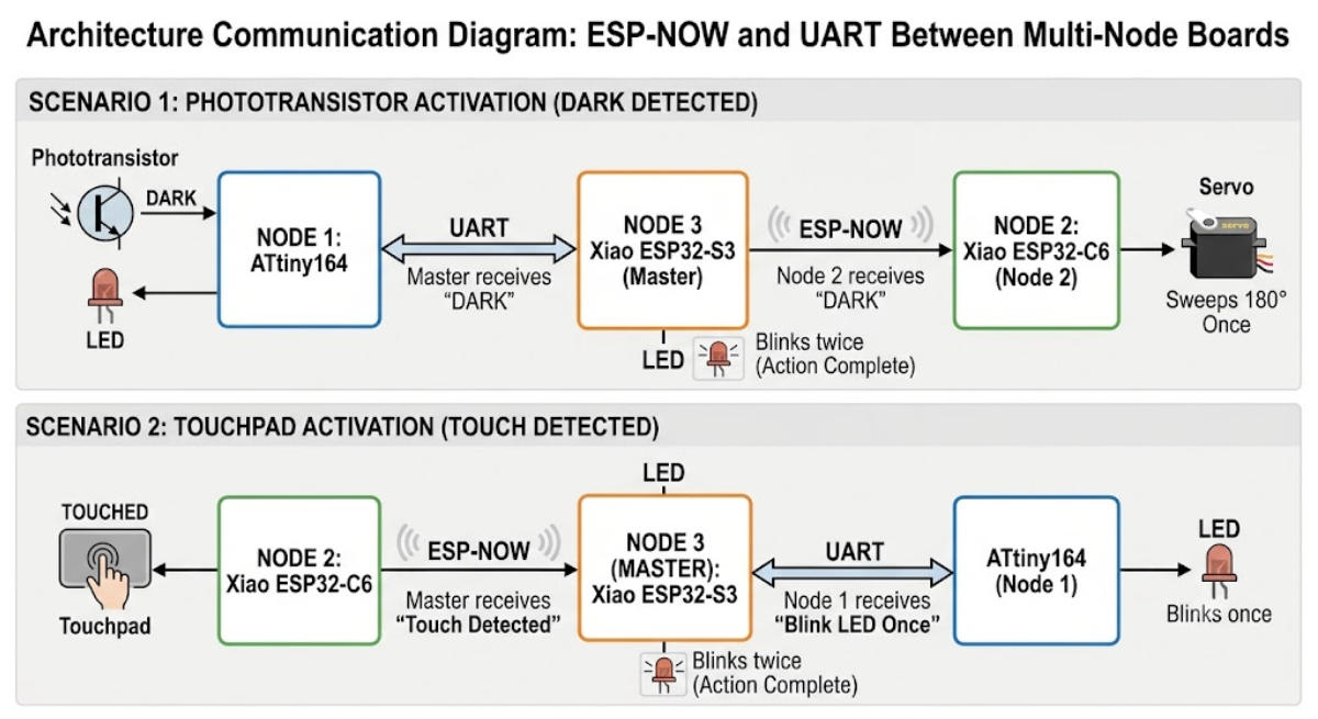
Prompt : Gemini- Draw a very simple but accurate architecture communication between boards using esp now and uart. There are three nodes. Node 1, which has an ATtiny164. Node 2, which has xiao ESP32-C6. And Node 3 also addressed as master, , with xiao ESP32-S3. Okay? There, now you have to draw the architectural communication between these boards. And if the node A, if on node A, the phototransistor sends a message dark, it is received by the master through UART connection, and that is transmitted to Node 2 via ESP-NOW connection, and the servo connected in the Node 2 sweeps 180 degrees once. And as a result, in master, the LED light blinks twice to denote the whole action is complete. And again, the next communication is from, in Node 2, if the touchpad is touched, the message touch detected is sent to master or aka Node 3. Node 3. And this is via ESP-NOW. And from the master, through UART connection, the message is sent to Node 1, saying it to blink the LED once. After this is over, the master, or the Node 3, the LED blinks twice to denote an action is complete. very easy to understand, clean
I have placed XIAO ESP32C6 on NODE 2 and XIAO ESP32S3 on MASTER. The rest is the same communicating between NODE 1 and NODE 2 over ESP NOW with MASTER.
Communication path 1: MASTER > ESP NOW > NODE 2
Communication path 2: MASTER > UART > NODE 1
Arduino IDE with ESP32 board package
ESP-NOW communication
MASTER: XIAO ESP32S3 , NODE 1: ATTINY1614 , NODE2: XIAO ESP32C6
NODE 1: ATTINY1614
PA1 : LED-A
* LED_PIN, HIGH);  // LED ON
* LED_PIN, LOW);   // LED OFF
PA2 : PHOTOTRANSISTOR
* lightValue 0 = dark, 1023 = bright
 *(lightValue < 200 ) DARK
 *(lightValue < 600) DIM
send to MASTER (ESP32S3)  via UART
PB2 : TX , PB3 : RX

NODE2: XIAO ESP32C6
D0 : microServo MG90S
*Standard servos move 0-180.
D6 : TOUCHPAD-N
* Receive ESP-NOW data
* const int TOUCH_THRESHOLD = 20000;
 if (touchValue < TOUCH_THRESHOLD) {
    Serial.print("Touch Detected! Value: ");

MASTER (ESP32S3):
UART connection to NODE1
D6 : TX
D7 : RX
D9 : LED-N
* TRUE turns LED ON
* FALSE turns LED OFF

CONDITIONS
Master connected to node 1 via UART. MATER to NODE 2 via ESP-NOW
action 1 - WHEN “Touch Detected “ IN TOUCHPAD-N  on NODE 2  , LED-A becomes LED_PIN, HIGH on NODE-1.
action 2 - When  PA2 : PHOTOTRANSISTOR light value is “DARK” , D0 : microServo MG90S on NODE 2 does 180degree sweep once.
When either one of these actions are complete on “D9 : LED-N” BLINKS TWICE with delay500 miliseconds on MASTER

Important:
* Code must compile without errors
* Use correct ESP-NOW callback signatures
* Do not include unnecessary code
* Keep CODES separate
* Keep the code simple and beginner friendly
* WiFi.mode(WIFI_STA); INCLUDE THIS ISN MAC ADDRESS CODE

GENERATE CODES IN THIS ORDER
code 1 : mac address : NODE-2 ESP32-C6
code 2: NODE-1 ATTINY1615
code 3: mac address : MASTER ESP32-S3
code 4: MASTER ESP32-S3
code 5: NODE-2 ESP32-C6
 GENERATE 1 CODE THEN TROUBLESHOOT AND THEN WILL ASK FOR THE NEXT CODE
I asked for step by step codes and also mentioned the order.
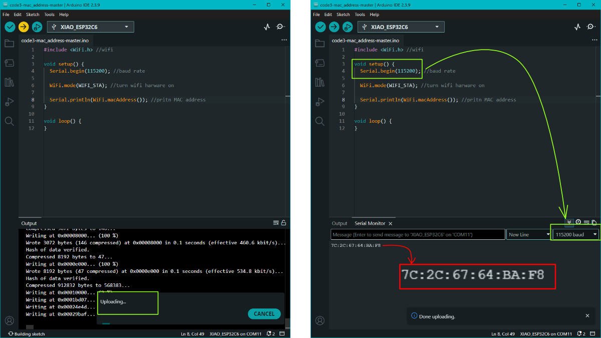
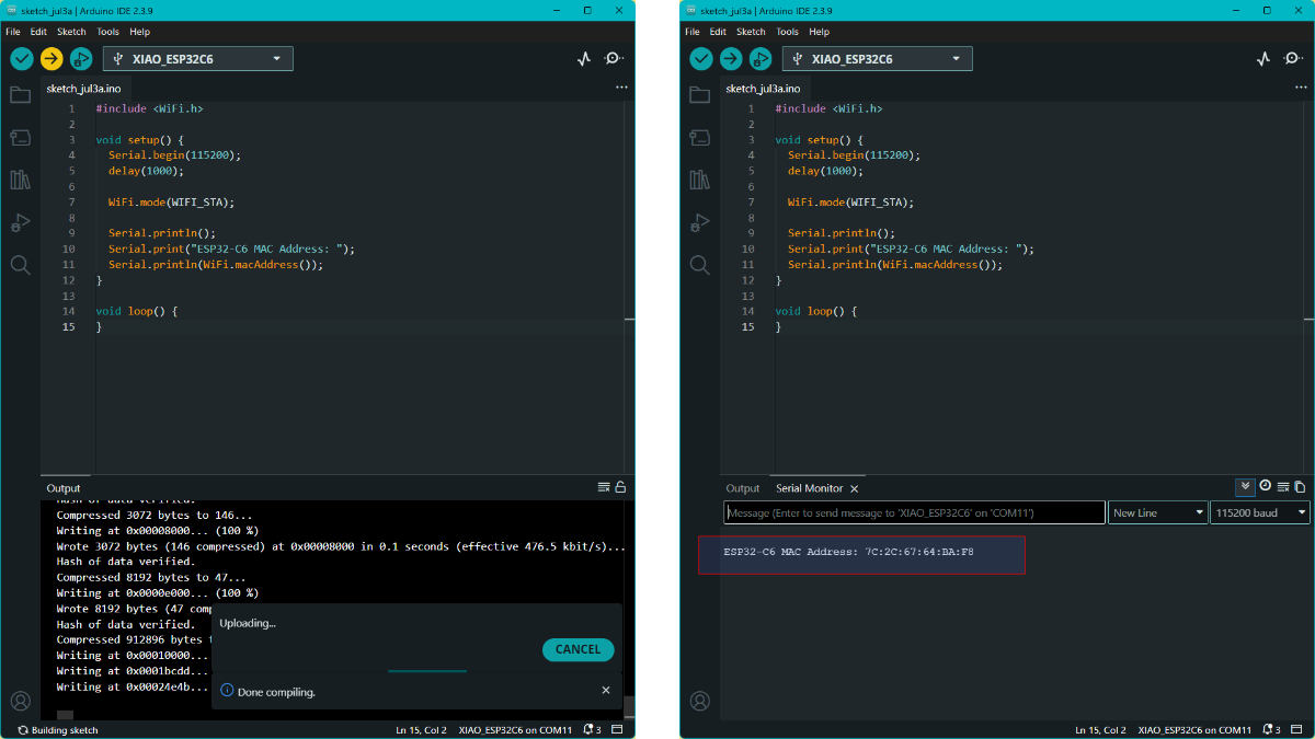
CODE 1 : MAC ADDRESS OF NODE 2 :ESP32-C6
#include

void setup() {
  Serial.begin(115200); //baud rate
  delay(1000); //delay 1 second

  WiFi.mode(WIFI_STA); //turn on wifi hardware

  Serial.println();
  Serial.print("ESP32-C6 MAC Address: "); //print ESP32-C6 MAC Address:
  Serial.println(WiFi.macAddress());  //the mac address
}

void loop() { //no loop added
}
I added to include WiFi.mode(WIFI_STA); in the code so that there will be no issues like last time.
NODE 2 : ESP32-C6MAC ADDRESS : 7C:2C:67:64:BA:F8
CODE 2 : NODE 1 : ATtiny1614
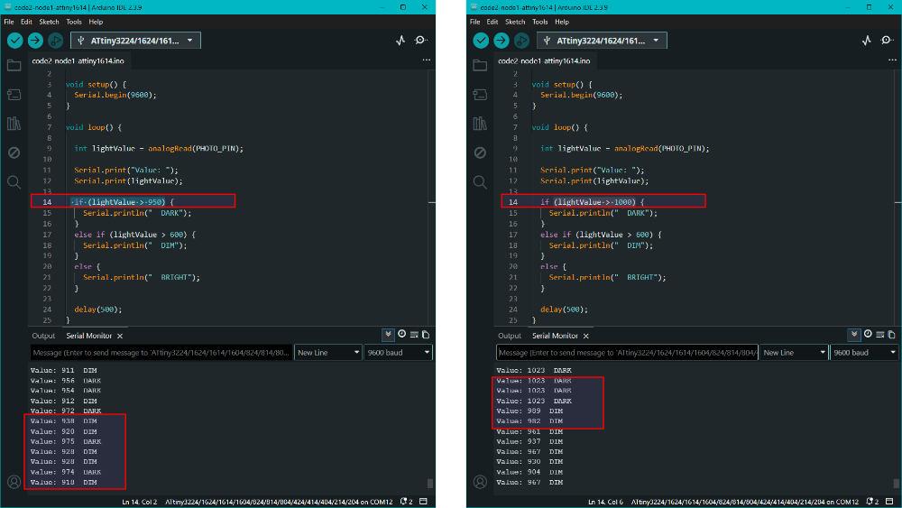
The phototransistor connected to it must send DARK to MASTER. MASTER forwards this to NODE 2 which in turn sweeps the servo connected to it. The initial code that ChatGPT gave had if (lightValue > 950). But the reading came out as DIM and DARK with slight variation under room light, and it read 120 values as BRIGHT. When covering it, it read 1024 or above 1000 as DARK. Therefore I changed the value to if (lightValue > 1000) { Serial.println(" DARK"); }
const int PHOTO_PIN = PIN_PA2; //phototransistor conencted to PA2

void setup() {
  Serial.begin(9600); //baud rate
}

void loop() {

  int lightValue = analogRead(PHOTO_PIN); //read the ligthvalue in loop

  Serial.print("Value: "); // print in loop "Value:"
  Serial.print(lightValue); // print the light value 100 or 956

  if (lightValue > 1000) { //if ligth value is more the 1000 print as DARK
    Serial.println("  DARK");
  }
  else if (lightValue > 600) { //if light value more tha 600 print DIM
    Serial.println("  DIM");
  }
  else {
    Serial.println("  BRIGHT"); //orelse  print BRIGHT
  }

  delay(500); //the delay in printing is .5seconds
}
The board settings followed are highlighted. Ctrl+Shift+U to upload. The code uploaded without error.
Troubleshooting : The light value was 950, but the phototransistor was reading values around 950 as DIM and DARK.
When covered, the value showed above 100. When light was shown, the reading was around 100.
To get a better steady DARK value, the light value was increased to 1000. Then the DARK and DIM values were stable, without fluctuation due to subtle changes.
CODE 3 : MAC ADDRESS OF MASTER : ESP32-S3
To get the MAC address of MASTER. This way the address is known of both XIAO ESP32 boards.
I got the MAC adress only with the second code #include <esp_wifi.h>This interacts directly with the low-level hardware drivers.
#include <WiFi.h> //library
#include <esp_wifi.h>  //library

void setup() {
  Serial.begin(115200); //baud rate is 115200
  delay(2000);

  WiFi.mode(WIFI_STA); //turn on wifi hardware
  delay(1000);

  uint8_t mac[6]; //mac address
  esp_wifi_get_mac(WIFI_IF_STA, mac);

  Serial.printf(
    "ESP32-S3 MAC Address: %02X:%02X:%02X:%02X:%02X:%02X\n", //the MAC address format
    mac[0], mac[1], mac[2],
    mac[3], mac[4], mac[5]
  );
}

void loop() { //no loop
}
MASTER : ESP32-S3 MAC Address: E0:72:A1:D7:7D:64
CODE 4 : MASTER : ESP32-S3
#include <WiFi.h>
#include <esp_now.h>

// NODE 2 ESP32-C6 MAC
uint8_t node2MAC[] = {0x7C, 0x2C, 0x67, 0x64, 0xBA, 0xF8}; //mac address of NODE 2 ESP32-C6

#define MASTER_TX D6 //tx pin
#define MASTER_RX D7 //rx pin
#define LED_N     D9 //led on master

HardwareSerial Node1Serial(1);

struct Message { //the message send or received 16 characters
  char text[16];
};

Message incomingMsg; //the incoming message

unsigned long ledOnTime = 0; //
bool ledTimerRunning = false;

// --------------------------------------------------
// Blink MASTER LED twice
// --------------------------------------------------
void blinkMasterLED() { //it pauses all actions and blinks LED twice fro confirmation
  for (int i = 0; i < 2; i++) {
    digitalWrite(LED_N, HIGH);
    delay(500);

    digitalWrite(LED_N, LOW);
    delay(500);
  }
}

// --------------------------------------------------
// Send ESP NOW message to NODE 2
// --------------------------------------------------
void sendToNode2(const char* text) { //add text into "struct Message" and transmits to NODE2
  Message msg;
  strcpy(msg.text, text);

  esp_now_send(node2MAC, (uint8_t*)&msg, sizeof(msg)); //sends the message to NODE 2
}

// --------------------------------------------------
// ESP NOW receive callback
// --------------------------------------------------
void onReceive(const esp_now_recv_info_t *info, //this an intruper trigger when node 2 send a message
               const uint8_t *data,
               int len) {

  memcpy(&incomingMsg, data, sizeof(incomingMsg));

  if (strcmp(incomingMsg.text, "TOUCH") == 0) { //if the incoming message is touch

    Node1Serial.println("LED_ON"); // the led turns high or on

    ledOnTime = millis(); //captures timestamp
    ledTimerRunning = true; //turns on for

    blinkMasterLED(); // after action confirmation blink
  }
}

void setup() {

  Serial.begin(115200); //baud

  pinMode(LED_N, OUTPUT); //led is output
  digitalWrite(LED_N, LOW); //led is off

  // UART to NODE 1
  Node1Serial.begin(9600, SERIAL_8N1, MASTER_RX, MASTER_TX);

  // ESP NOW
  WiFi.mode(WIFI_STA);

  if (esp_now_init() != ESP_OK) { //Initializes the ESP-NOW wireless protocol,
    Serial.println("ESP NOW Init Failed");
    return;
  }

  esp_now_register_recv_cb(onReceive); //function to listen for incoming data

  esp_now_peer_info_t peerInfo = {};

  memcpy(peerInfo.peer_addr, node2MAC, 6); //pairs the Master explicitly with NODE 2's MAC address
  peerInfo.channel = 0;
  peerInfo.encrypt = false;

  esp_now_add_peer(&peerInfo);

  Serial.println("MASTER READY"); //outputs "MASTER READY"
}

void loop() { //main loop

  // Read UART from NODE 1
  if (Node1Serial.available()) {  //Continuously listens for data coming from NODE 1

    String msg = Node1Serial.readStringUntil('\n');
    msg.trim();

Serial.print("UART Received: "); // to print the message from attiny
Serial.println(msg);

if (msg == "DARK") { //if teh message is dark then follow the below steps

  Serial.println("DARK detected"); //if DARK detected

  sendToNode2("SWEEP"); //do the sweep action

  blinkMasterLED(); //then blik the master led
}
  }

  // Turn LED-A OFF after 1 second
  if (ledTimerRunning) {

    if (millis() - ledOnTime >= 1000) { //if touch was send

      Node1Serial.println("LED_OFF"); //led turns off after 1 second

      ledTimerRunning = false;
    }
  }
}
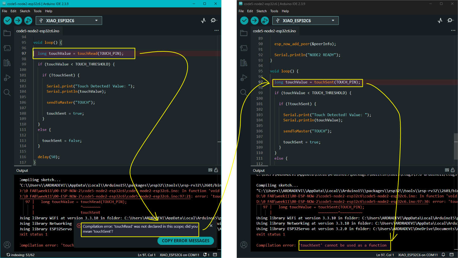
Troubleshooting : The error appeared because of long touchValue = touchRead(TOUCH_PIN);. The error message suggested that I might have meant touchSent. I changed it in the code, but the error still remained.
Then ChatGPT explained that touchRead() works on ESP32 and ESP32-S3 touch capable pins, but the ESP32-C6 does not have the same capacitive touch peripheral. I had previously used the touch pad connection successfully, so I added that code and asked ChatGPT to rewrite the code so that the pin would work.
CODE 5 : NODE 2 : ESP32-C6
Functions done by this code:
The pins are defined as D0 = MG90S Servo and D6 = Touch Pad. It sends the message "TOUCH" to MASTER when touched on NODE 2. It receives "SWEEP" from MASTER (when the phototransistor prints DARK). It performs one 0° → 180° → 0° sweep. The MAC address used is MASTER MAC: E0:72:A1:D7:7D:64. It also includes WiFi.mode(WIFI_STA); to turn on the Wi-Fi hardware. It is compatible with ESP32 board package 3.3.10.
#include <WiFi.h>
#include <esp_now.h> //esp-now
#include <ESP32Servo.h> // ESP32Servo library

const int SERVO_PIN = D0; //the pins
const int TOUCH_PIN = D6;
const int TOUCH_THRESHOLD = 2000; // touch threshold adjusted to 2000

Servo myServo;

// MASTER ESP32-S3 MAC
uint8_t masterMAC[] = { // MAC ADRESS MASTER ESP32-S3
  0xE0, 0x72, 0xA1,
  0xD7, 0x7D, 0x64
};

struct Message { //the text box
  char text[16];
};

Message incomingMsg;

bool touchSent = false;

// --------------------------------------------------
// Servo Sweep
// --------------------------------------------------
void servoSweep() { //if touch is detected

  myServo.write(0); //with delay of .3seconds at 0
  delay(300);

  myServo.write(180); //with delay of 1 second at 180degree sweep
  delay(1000);

  myServo.write(0);
  delay(1000);
}

// --------------------------------------------------
// Send ESP-NOW Message
// --------------------------------------------------
void sendToMaster(const char* text) { //to send text

  Message msg;
  strcpy(msg.text, text);

  esp_now_send(masterMAC, (uint8_t*)&msg, sizeof(msg));
}

// --------------------------------------------------
// Receive Callback
// --------------------------------------------------
void onReceive(const esp_now_recv_info_t *info,
               const uint8_t *data,
               int len) {

  memcpy(&incomingMsg, data, sizeof(incomingMsg)); //the incoming data

  if (strcmp(incomingMsg.text, "SWEEP") == 0) {

    Serial.println("SWEEP RECEIVED"); //when sweep i noted

    servoSweep();
  }
}

void setup() {

  Serial.begin(115200);

  myServo.attach(SERVO_PIN); // the servo pin has to move
  myServo.write(0);

  WiFi.mode(WIFI_STA);

  if (esp_now_init() != ESP_OK) {
    Serial.println("ESP-NOW Init Failed");
    return;
  }

  esp_now_register_recv_cb(onReceive);

  esp_now_peer_info_t peerInfo = {};

  memcpy(peerInfo.peer_addr, masterMAC, 6);
  peerInfo.channel = 0;
  peerInfo.encrypt = false;

  esp_now_add_peer(&peerInfo);

  Serial.println("NODE2 READY"); //prints node 2 readyw ehn uploaded
}

void loop() {

pinMode(TOUCH_PIN, OUTPUT);
digitalWrite(TOUCH_PIN, LOW);
delayMicroseconds(10);

pinMode(TOUCH_PIN, INPUT);

int count = 0;

while (digitalRead(TOUCH_PIN) == LOW) {
  count++;
}

Serial.print("Touch Value: ");
Serial.println(count);

if (count < TOUCH_THRESHOLD) {

  if (!touchSent) {

    Serial.println("TOUCH DETECTED"); //when count cycle is less than threshold value

    sendToMaster("TOUCH");

    touchSent = true;
  }
}
else {

  touchSent = false;
}
  delay(50);
}
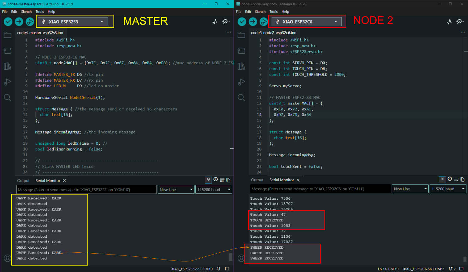
When I cover the phototransistor on NODE 1, the value goes above 1000. This triggers DIM. NODE 1, connected to the MASTER, sends the DIM signal. The MASTER transmits this value to NODE 2 as DIM, and it performs the SWEEP action. Once the action is complete, the LED on the MASTER blinks twice.
On NODE 2, when the touch pad is touched, NODE 2 sends the TOUCHED signal to the MASTER. This triggers NODE 1 to turn the LED on and then off. After this is done, the LED on the MASTER blinks twice.
The first action is interaction with the touch pad on NODE 2. The LED on NODE 1 lights up, and after that, the MASTER LED blinks twice to denote that the action is complete.
The second action is covering the phototransistor on NODE 1. The servo on NODE 2 sweeps, and the LED on the MASTER blinks twice after that.
Communication is not just a single way process. For better interaction, it is always good to communicate in both directions. NODE 1 speaks to NODE 2 through the MASTER. NODE 2 also speaks to NODE 1 through the MASTER. When NODE 1 and NODE 2 communicate, the MASTER also acknowledges it by blinking.
BLE : RTC + SERVO
Communication flow. The communication does not meet the assignment conditions. It needs reverse communication as well.
i need two xiao boardS to communincate with eachother by ESP-NOW. CREATE SIMPLE ARDUINO CODES. XIAO ESP32C6 IS THE SENDER, HEREAFTER BE CALLED C6 XIAO ESP32S3 IS THE RECEIVER, HEREAFTER BE CALLED S3 RECEIVER MAC ID IS 30:30:f9:34:60:2c USE 115200 BAUD WHEN I PRESS THE TOUCH PAD (PIN D6) ON C6 BOARD . IN S3 BOARD I NEED THE LED CONNECTED TO PIN D9 TO TURN ON. Touched ≈ 70 Not touched ≈ 1000 TOUCH ARDUINO CODE: #define TOUCH_PIN D6 int threshold = 500; // adjust based on your readings void setup() { Serial.begin(115200); } void loop() { // Discharge pin pinMode(TOUCH_PIN, OUTPUT); digitalWrite(TOUCH_PIN, LOW); delayMicroseconds(10); // Switch to input and measure charge time pinMode(TOUCH_PIN, INPUT); int count = 0; while (digitalRead(TOUCH_PIN) == LOW) { count++; } Serial.print("Value: "); Serial.println(count); // Your case: touched = LOWER value if (count < threshold) { Serial.println("TOUCHED"); } else { Serial.println("NOT TOUCHED"); } Serial.println("------------------"); delay(1500); // slower (1.5 seconds) } LED BLINK TEST CODE: #define LED_PIN D9 // Define pin D9 void setup() { pinMode(LED_PIN, OUTPUT); // Set D9 as output } void loop() { digitalWrite(LED_PIN, HIGH); // Turn LED ON delay(1000); // Wait 1 second digitalWrite(LED_PIN, LOW); // Turn LED OFF delay(1000); // Wait 1 second } WRITE CODES REFERING THE ABOVE TO AVOID ERRORS. GIVE SIMPLE , CLEAN SENDER AND RECEIVER CODES, WITHOUT ERROR
NODE 1- RTC
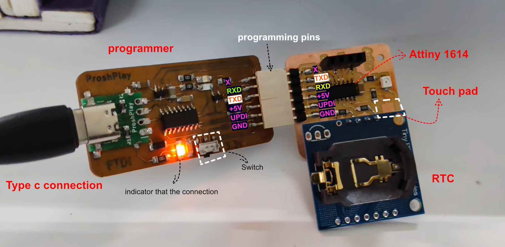
ATtiny1614 - Input week
"I asked AI to program it so that the RTC would display the time in seconds when connected." Well, I wish that was actually what I did. I did not understand a lot of what was happening, and most of the code I got was messy. The communication between the boards was not working. After a lot of back and forth with ChatGPT and Gemini, I eventually got the code working. I have included one such interaction where I got the code. It is a lengthy conversation: Interaction with Gemini.
What I would suggest doing next time is programming each action separately, testing it, and then gradually adding more functionality to the code later.
Programming the ATtiny1614 using a programmer. I am reusing an image from Week 9 to show the connection, as it is the same setup.
NODE 1 - RTC
Library needed: RTClib by Adafruit.
This code reads data from the RTC using I2C and sends the seconds count to the ESP32-S3 via UART. I upload this code first. Since there is no coin cell battery on the RTC, the time starts from 0 as soon as it is plugged in.
        #include <Wire.h>
#include "RTClib.h"

RTC_DS3231 rtc;

void setup() {
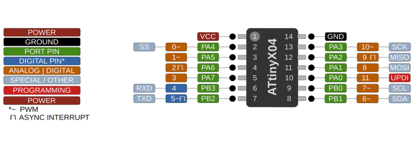
  // ATtiny1614 Serial (TX:PB2, RX:PB3)
  Serial.begin(9600);
  Wire.begin(); // SCL:PB0, SDA:PB1

  if (!rtc.begin()) {
    while (1); // Stop if RTC not found
  }
}

void loop() {
  DateTime now = rtc.now();

  // We send just the "Seconds" as a string to simplify the trigger
  Serial.println(now.second());

  delay(1000);
}
MASTER - BREAKOUT BOARD
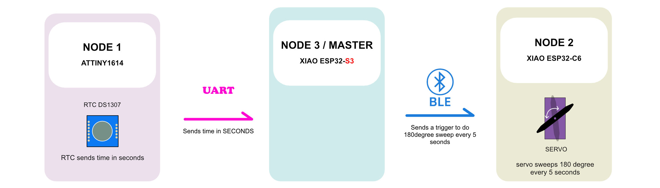
The master listens to and receives data from Node 1 (ATtiny1614) via UART and "broadcasts" that value over BLE.
    #include <BLEDevice.h>
#include <BLEUtils.h>
#include <BLEServer.h>

#define SERVICE_UUID        "4fafc201-1fb5-459e-8fcc-c5c9c331914b"
#define CHARACTERISTIC_UUID "beb5483e-36e1-4688-b7f5-ea07361b26a8"

BLECharacteristic *pCharacteristic;
bool deviceConnected = false;

// We need a class to handle connection status
class MyServerCallbacks: public BLEServerCallbacks {
    void onConnect(BLEServer* pServer) { deviceConnected = true; };
    void onDisconnect(BLEServer* pServer) {
      deviceConnected = false;
      BLEDevice::startAdvertising(); // Restart advertising when disconnected
      Serial.println("Device disconnected, restarting advertising...");
    }
};

void setup() {
  Serial.begin(115200);
  // On S3, Serial1 pins are 44 (RX) and 43 (TX)
  Serial1.begin(9600, SERIAL_8N1, 44, 43);

  Serial.println("Initializing S3 BLE...");

  BLEDevice::init("XIAO_S3_SENDER");
  BLEServer *pServer = BLEDevice::createServer();
  pServer->setCallbacks(new MyServerCallbacks());

  BLEService *pService = pServer->createService(SERVICE_UUID);

  pCharacteristic = pService->createCharacteristic(
                      CHARACTERISTIC_UUID,
                      BLECharacteristic::PROPERTY_READ   |
                      BLECharacteristic::PROPERTY_WRITE  |
                      BLECharacteristic::PROPERTY_NOTIFY |
                      BLECharacteristic::PROPERTY_INDICATE
                    );

  pService->start();

  // Explicitly setup advertising
  BLEAdvertising *pAdvertising = BLEDevice::getAdvertising();
  pAdvertising->addServiceUUID(SERVICE_UUID);
  pAdvertising->setScanResponse(true);
  pAdvertising->setMinPreferred(0x06);
  pAdvertising->setMinPreferred(0x12);

  BLEDevice::startAdvertising();
  Serial.println("S3 is now advertising! Check your phone now.");
}

void loop() {
  // Check if ATtiny sent data
  if (Serial1.available()) {
    String tinyData = Serial1.readStringUntil('\n');
    tinyData.trim(); // Remove any hidden spaces/newlines

    if (tinyData.length() > 0) {
      pCharacteristic->setValue(tinyData.c_str());
      pCharacteristic->notify();
      Serial.print("Data from ATtiny sent to BLE: ");
      Serial.println(tinyData);
    }
  }

  // Heartbeat to Serial Monitor so you know the S3 hasn't crashed
  static unsigned long lastTime = 0;
  if (millis() - lastTime > 5000) {
    Serial.println("S3 is alive and waiting for ATtiny data...");
    lastTime = millis();
  }
}
NODE 2 - OUTPUT WEEK
This code runs on a XIAO ESP32-C6 acting as a BLE receiver. It scans for and connects to a BLE sender, receives RTC seconds data, and monitors incoming values. Whenever the received seconds value is a multiple of 5, the servo connected to D0 rotates to 180° and returns to 0°.
#include <BLEDevice.h>
#include <ESP32Servo.h>


#define SERVICE_UUID        "4fafc201-1fb5-459e-8fcc-c5c9c331914b"
#define CHARACTERISTIC_UUID "beb5483e-36e1-4688-b7f5-ea07361b26a8" //The sender and receiver must use the same UUIDs to communicate.

Servo myServo; //UUID (Universally Unique Identifier) is a unique ID used in BLE to identify services and characteristics.
int servoPin = 0; // D0 on C6
static BLEUUID binServiceUUID(SERVICE_UUID);
static BLEUUID binCharUUID(CHARACTERISTIC_UUID);
bool doConnect = false;
BLERemoteCharacteristic* pRemoteChar;
BLEAdvertisedDevice* myDevice;

// --- UPDATED SERVO FUNCTION WITH REAL-TIME MONITORING ---
void sweepServo() {
  Serial.println(">>> 5 SECOND MARK DETECTED!");

  Serial.print("Moving to 180°... "); //moves 180 degree
  myServo.write(180);
  Serial.println("[DONE]");

  delay(500); // Wait for the motor to physically reach the spot waits 0.5seconds

  Serial.print("Returning to 0°... "); //returns to 0 degree
  myServo.write(0);
  Serial.println("[DONE]");

  Serial.println("Sweep Cycle Complete. Waiting for next 5s mark...\n");
}

static void notifyCallback(BLERemoteCharacteristic* pChar, uint8_t* pData, size_t length, bool isNotify) {
  String val = "";
  for (int i = 0; i < length; i++) val += (char)pData[i];

  int seconds = val.toInt();
  Serial.print("RTC Time Received: ");
  Serial.print(seconds);
  Serial.println("s");

  // Trigger sweep every 5 seconds
  if (seconds % 5 == 0 && seconds != 0) {
    sweepServo();
  }
}

class MyCallbacks: public BLEAdvertisedDeviceCallbacks {
  void onResult(BLEAdvertisedDevice advertisedDevice) {
    if (advertisedDevice.isAdvertisingService(binServiceUUID)) {
      BLEDevice::getScan()->stop();
      myDevice = new BLEAdvertisedDevice(advertisedDevice);
      doConnect = true;
    }
  }
};

void setup() {
  Serial.begin(115200);
  myServo.attach(servoPin);
  myServo.write(0); // Initialize at zero

  BLEDevice::init("XIAO_C6_RECEIVER");
  BLEScan* pScan = BLEDevice::getScan();
  pScan->setAdvertisedDeviceCallbacks(new MyCallbacks());
  pScan->setActiveScan(true);
  pScan->start(30);

  Serial.println("C6 Receiver Started. Scanning for S3 Sender...");
}

void loop() {
  if (doConnect) {
    BLEClient* pClient = BLEDevice::createClient();
    if(pClient->connect(myDevice)) {
      Serial.println("--- CONNECTED TO S3 SENDER ---");
      BLERemoteService* pService = pClient->getService(binServiceUUID);
      if (pService != nullptr) {
        pRemoteChar = pService->getCharacteristic(binCharUUID);
        if (pRemoteChar != nullptr) {
           pRemoteChar->registerForNotify(notifyCallback);
           Serial.println("Monitoring RTC data...");
        }
      }
    } else {
      Serial.println("Connection failed. Retrying scan...");
      BLEDevice::getScan()->start(30);
    }
    doConnect = false;
  }
}
The RTC on the node 1 sends time to Master through UART which prints the seconds on the serial monitor. Through BLE the servo on node 2 does a 180 degree sweep every 5 seconds.
Group Assignment
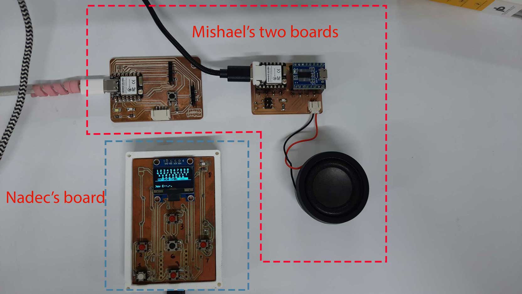
We communcated with 2 projects. Nadec's and Mishael's
For this week's group assignment, we established communication between two different project's boards using both Wi Fi (TCP) and ESP NOW.
Nadec's custom ESP32 board acted as Master - a Wi Fi access point and TCP server. It had six push buttons and an OLED display. Using the buttons, text could be typed on a QWERTY keyboard displayed on the OLED screen. Mishael's setup consisted of two XIAO ESP32 C6 boards. these were the nodes. The first node connected to Nadec's Wi Fi network and received the text through TCP communication. This node then forwarded the received message to a second XIAO ESP32 C6 node using ESP NOW.
The second node was connected to an MP3 player module and speaker. When it received the message, it played the corresponding audio file through the speaker.
The complete communication flow was:
Text entered on Nadec's OLED screen → sent through Wi Fi using TCP → received by Mishael's node 1 → forwarded through ESP NOW → received by the node 2 → audio played through the speaker.
Through this assignment, we learned how different communication protocols can be combined in a single system to transfer data between multiple nodes and trigger an output device.