Week 11: Networking and Communications
Assignments
Individual Assignment
I need to design and build one or more nodes that can communicate with each other, either through wired or wireless means. Each node should have its own identity (an address on the network or bus), and it shouldn’t just sit there, it needs to do something locally, like take an input (button, sensor) or produce an output (LED, sound, etc.). So essentially, I’m making a small system where each part can send, receive, and act.
Relevance of Networking & Communication Week
This week is about shifting the way I think about electronics, instead of a single microcontroller doing everything, the focus is on building systems where multiple nodes communicate and coordinate with each other. The core idea is that two separate devices can talk to each other wirelessly, each doing its own job but responding to what the other sends.
The protocol I will be exploring this week is ESP-NOW, a lightweight peer-to-peer communication protocol built into ESP32 chips. What makes it interesting is that it requires no router, no internet connection, and no external network infrastructure. Two boards can find each other and exchange messages directly, which makes it fast, simple, and well suited for embedded systems work.
To put this into practice, I plan to use two boards I have already built from previous weeks, which makes the exercise feel more meaningful than starting from scratch:
The plan is straightforward: pressing a button on Board 1 will send a wireless message via ESP-NOW, and Board 2 will respond by playing an MP3 file. No wires between them. It is a small interaction, but it captures everything essential about networked communication, a trigger, a message, and a response.
What I hope to understand through this is how many real-world embedded systems are actually built this way, with multiple boards each handling what they are good at, coordinating through messages rather than being wired into one overloaded controller. That shift in thinking is what feels most relevant to take forward.
For my final project specifically, this is directly applicable. My piggy bank may need two boards working together internally due to pin limitations, and ESP-NOW is a strong candidate for how they could communicate. But beyond the project, this week gives me a protocol and a mental model I can reach for whenever a single microcontroller is not enough.
How Devices Talk to Each Other
Youtube tutorial PROTOCOLS: UART - I2C - SPI - Serial communications #001
Website for additional information UART vs I2C vs SPI – Communication Protocols and Uses
A beginner's guide to the four layers of device communication - physical transmission, timing, protocols (UART, I2C, SPI), and wireless systems (Wi-Fi & Bluetooth).
Layer 1: Physical transmission - Serial vs Parallel
Before any protocol or timing exists, you need a basic answer: how do bits physically travel from A to B?
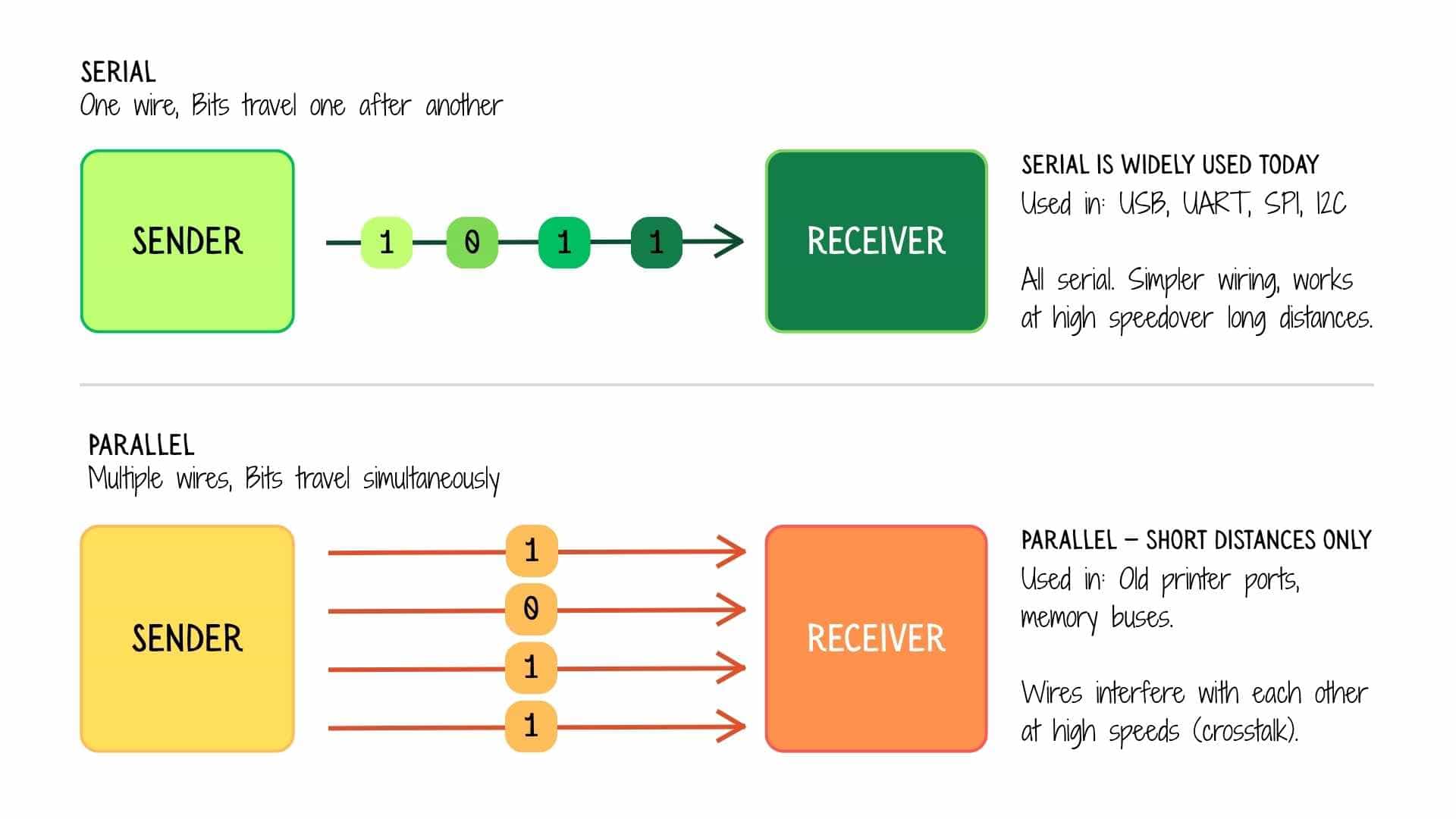
Serial sends one bit at a time down a single wire. It's simpler, cheaper, and works well over longer distances. Most modern communication - USB, UART, I2C, SPI - is serial.
Parallel sends multiple bits simultaneously across multiple wires. It's faster in theory, but the wires must all stay perfectly in sync, which gets harder as distance or speed increases. This is why parallel eventually lost to fast serial (USB replaced the old parallel printer port, for example). Today, parallel is mainly found internally, inside a chip communicating with RAM on a short bus.
Layer 2: Timing - Synchronous vs Asynchronous
Now that bits are travelling on a wire, both sides need to agree on when to sample those bits. This is the timing problem.
Imagine someone sending you dots and dashes in Morse code. Without knowing the rhythm, you can't tell where one letter ends and the next begins. Synchronous and asynchronous are two different solutions to this problem.
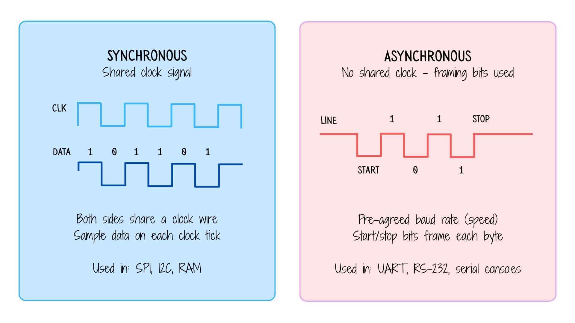
Synchronous communication includes a dedicated clock wire (CLK). The sender toggles the clock, and the receiver reads the data line on every tick, like two people clapping hands in sync. Both sides are always in lockstep. SPI and I2C work this way.
Asynchronous communication has no clock wire. Instead, both sides agree on a speed in advance (the baud rate, e.g. 9600 bits per second). The sender wraps each byte in a start bit and a stop bit, so the receiver knows exactly where each byte begins and ends. UART works this way, which is why you configure baud rate when setting up a serial console.
Layer 3: Protocols - UART, I2C, SPI
Protocols are the agreed-upon rules that govern how devices actually talk. They decide: who initiates, how many wires, how many devices can be on one bus, and how errors are handled.
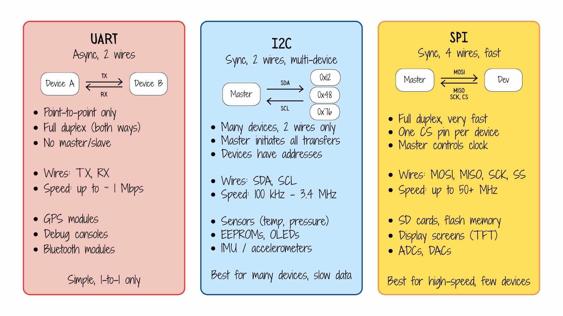
UART (Universal Asynchronous Receiver-Transmitter) is the simplest. Two devices connect directly, TX from one goes into RX of the other, and vice versa. No clock wire. No addresses. Just two wires and a pre-agreed speed. It can only connect one device to one device, making it perfect for debug consoles, GPS modules, and Bluetooth dongles (HC-05 style).
I2C (Inter-Integrated Circuit) is the smart-bus protocol. It uses just two wires - SDA (data) and SCL (clock), shared across all devices on the bus. Every device has a unique 7-bit address. The master says "hey, 0x48, I want your temperature reading" and only device 0x48 responds. This makes it ideal when you need to connect many slow sensors (temperature, humidity, pressure, IMU) using minimal wiring. The tradeoff is lower speed.
SPI (Serial Peripheral Interface) is the fast lane. It uses four wires, MOSI (master out, slave in), MISO (master in, slave out), SCK (clock), and SS/CS (chip select, one per device). It's full duplex (data flows both ways simultaneously) and can run at tens of MHz. The cost is more wires and a dedicated chip-select line for every device you add. SD cards, flash memory chips, and TFT displays are classic SPI users.
Layer 4: Wireless systems - Wi-Fi and Bluetooth
Wireless systems follow all the same logic above, they still use serial data, timing, and their own protocols but replace the physical wire with radio waves.
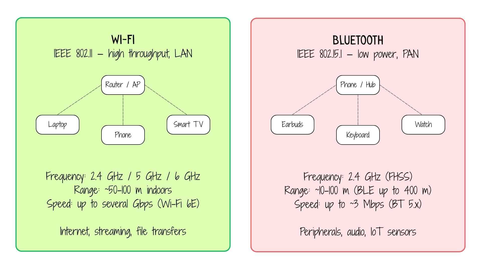
Wi-Fi is designed for high-throughput data - streaming video, web browsing, file downloads. It connects devices to a central access point (your router), which then routes traffic to the internet or your local network. It operates on 2.4 GHz, 5 GHz, or 6 GHz bands. The 2.4 GHz band travels further through walls but gets congested; 5/6 GHz is faster but shorter range. Think of Wi-Fi as the highway system for your home network.
Bluetooth is designed for short-range, low-power device pairing. Classic Bluetooth handles audio (earbuds, speakers) and data transfer. BLE (Bluetooth Low Energy), introduced in Bluetooth 4.0, is a different mode optimised for tiny packets sent infrequently, perfect for IoT sensors, wearables, and beacons that run for months on a small battery. Bluetooth uses frequency hopping spread spectrum (FHSS), it hops between 79 channels 1,600 times per second, which makes it resistant to interference from Wi-Fi and microwaves sharing the same 2.4 GHz band.
Quick reference summary
Prompt used on Chat GPT:


Based on the references and links provided, create a simple comparison table that brings together the key points in one place. Focus on quick understanding rather than detailed specifications. Highlight the main differences, strengths, limitations, and typical use cases of each option. Keep the content concise, technically accurate, and easy to scan as a future reference. Include only the most relevant comparison criteria and avoid unnecessary details.
| Feature | UART | I2C | SPI | Wi-Fi | Bluetooth |
|---|---|---|---|---|---|
| Wires | 2 | 2 | 4+ | None (radio) | None (radio) |
| Clock | No (async) | Yes | Yes | No | No |
| Devices | 1-to-1 | Many (addresses) | Few (CS pins) | Many (AP) | ~7 active |
| Speed | ~1 Mbps | 100 kHz–3.4 MHz | 50+ MHz | Gbps | ~3 Mbps |
| Typical use | Debug, GPS | Sensors, EEPROM | Flash, displays | Internet | Audio, peripherals |
ESP-NOW Communication Between Two XIAO ESP32-C6 Boards

I began by exploring ESP-NOW, a lightweight wireless communication protocol developed by Espressif Systems. Unlike Wi-Fi or Bluetooth, ESP-NOW doesn’t require a router, pairing process, or internet connection. It allows two microcontrollers to communicate directly using their MAC addresses, making it fast, simple, and efficient for embedded systems.
Youtube video referenced: ESP32's HIDDEN Wireless Superpower (ESP-NOW Tutorial),
P-NOW with ESP32 EXPLAINED: Easiest Wireless Communication Between Boards
Setting Up the Boards
I used two Seeed Studio XIAO ESP32-C6 boards:
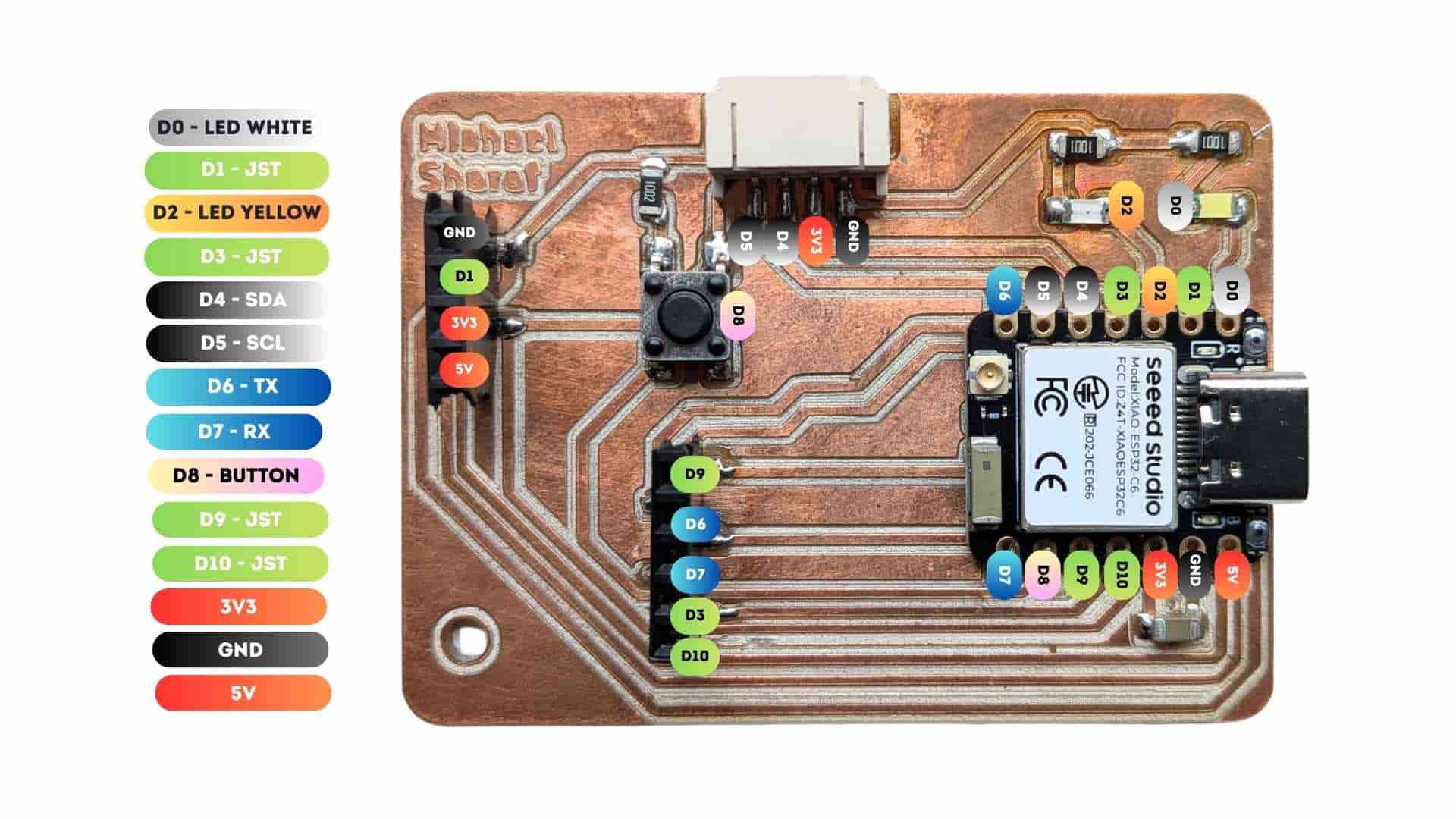
Board 1 (Sender): Button Input
For board details, refer week 8: Electronics Production
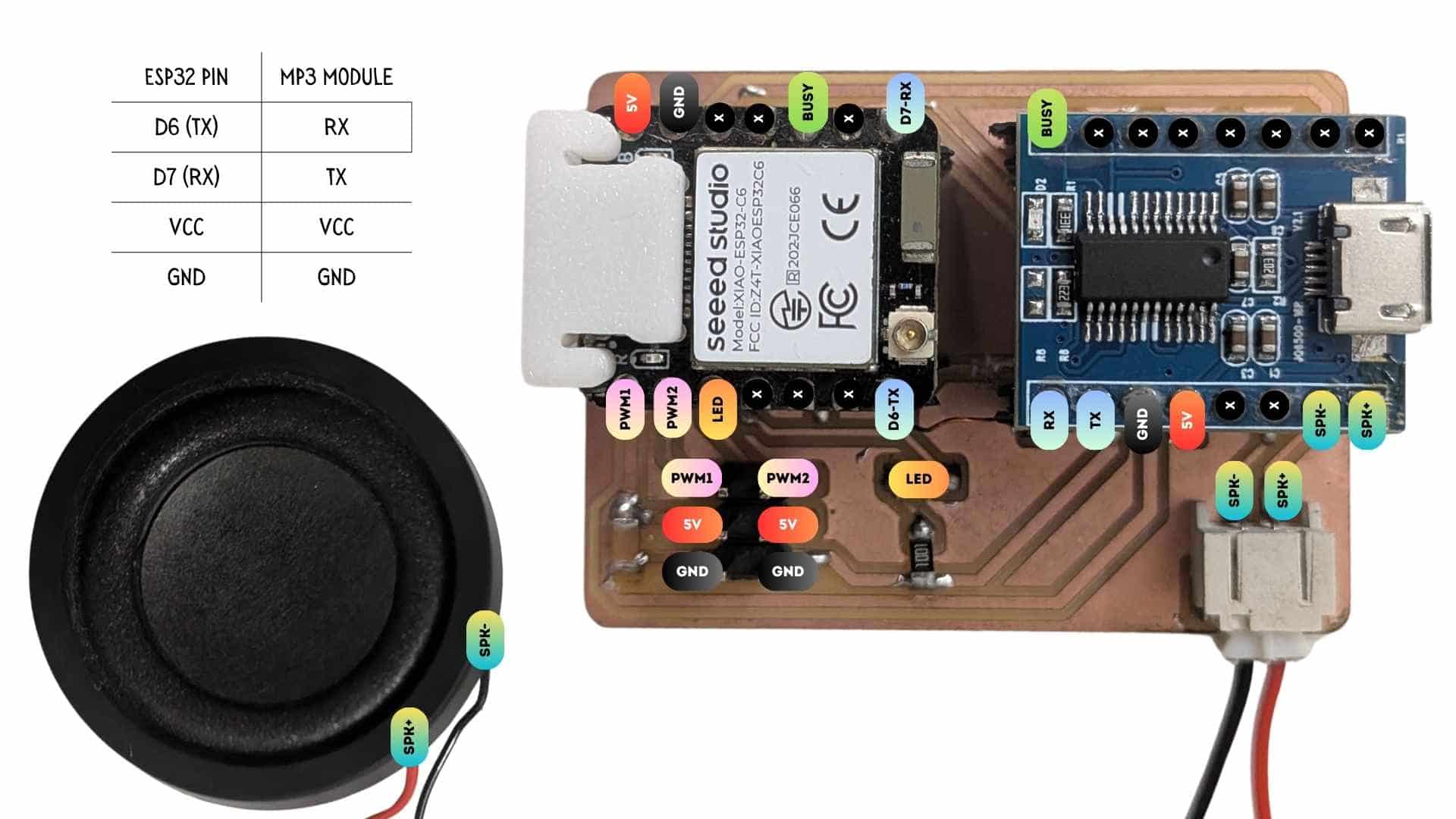
Board 2 (Receiver): JQ6500 Mp3 Module + speaker
For board details, refer week 10: Output Devices
The goal was to first establish a reliable ESP-NOW link between the boards.
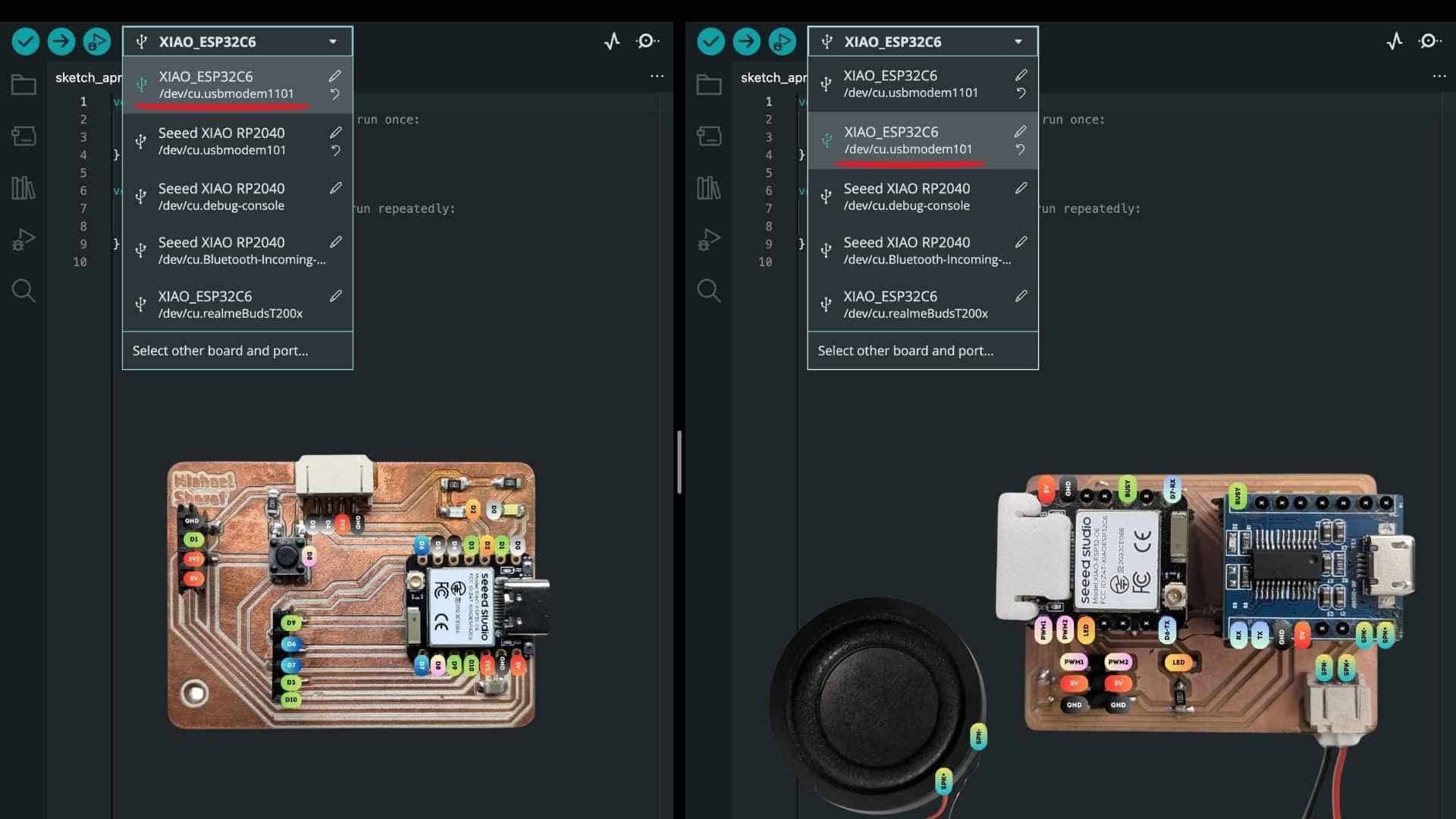
Both boards were connected to my laptop via USB. In the Arduino IDE, each board appeared as a different serial port. This step is critical, each board must be selected and monitored independently.
Identifying MAC Addresses
Reference used Getting Started with ESP-NOW (ESP32 with Arduino IDE)
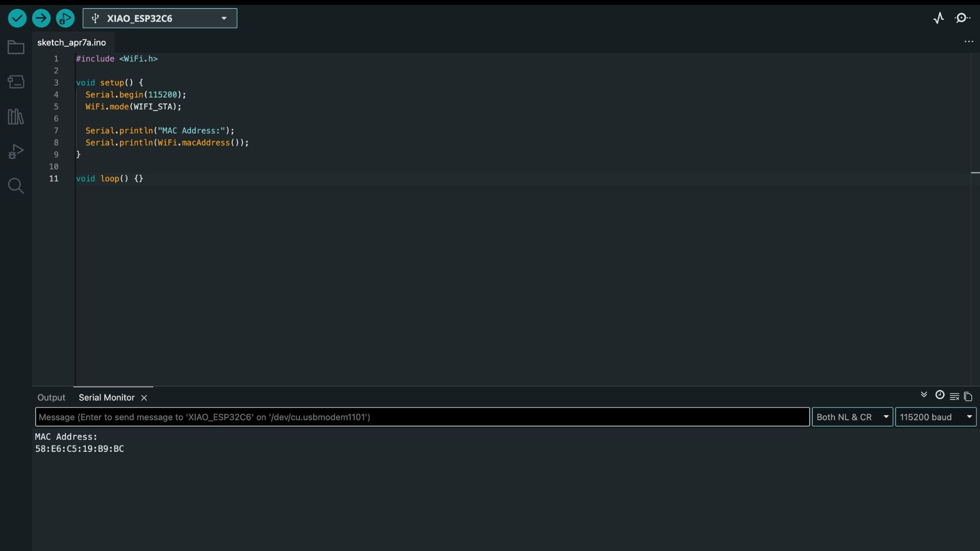
Since ESP-NOW relies on MAC addressing, the first step was to retrieve the unique MAC address of each board.
Prompt used on ChatGPT:
Write a simple Arduino program for a Seeed Studio XIAO ESP32-C6 that prints its MAC address to the Serial Monitor.

Use a baud rate of 115200, set the board to Wi-Fi station mode, and display the MAC address clearly so it can be copied and used for ESP-NOW communication.
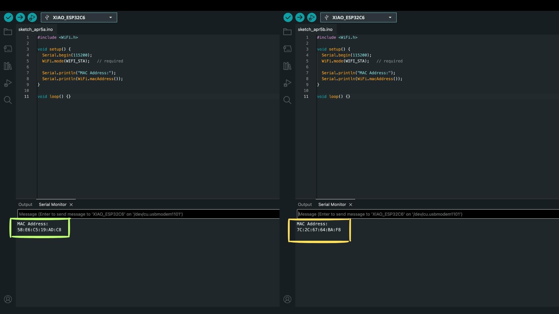
I uploaded the following code to each board:
#include <
WiFi.h> void setup() { Serial.begin(115200); WiFi.mode(WIFI_STA); Serial.println("MAC Address:"); Serial.println(WiFi.macAddress()); } void loop() {}
Important detail
The baud rate must be set to 115200 in the Serial Monitor.
If this does not match Serial.begin(115200);, no readable output appears.
After uploading and opening the Serial Monitor (sometimes pressing reset helps), I obtained:
The receiver’s MAC address is then used in the sender code to define the communication target.
Testing ESP-NOW Communication
Before integrating any hardware, I tested communication by sending simple numeric data.
Prompt used on ChatGPT:
Create two simple Arduino programs for two Seeed Studio XIAO ESP32-C6 boards using ESP-NOW.

One board should send a random number (1–4) every second to the other board using its MAC address 7C:2C:67:64:BA:F8.

The second board should receive this number and display it in the Serial Monitor.

Keep the setup simple, use a baud rate of 115200, and make sure both boards can clearly show the sending and receiving values.
Code Used for Sender (Board 1):
#include <
WiFi.h> #include <esp_now.h> uint8_t peerAddress[] = {0x7C, 0x2C, 0x67, 0x64, 0xBA, 0xF8}; typedef struct struct_message { int value; } struct_message; struct_message msg; void setup() { Serial.begin(115200); WiFi.mode(WIFI_STA); if (esp_now_init() != ESP_OK) { Serial.println("ESP-NOW init failed"); return; } esp_now_peer_info_t peerInfo = {}; memcpy(peerInfo.peer_addr, peerAddress, 6); peerInfo.channel = 0; peerInfo.encrypt = false; esp_now_add_peer(&peerInfo); } void loop() { msg.value = random(1, 5); Serial.print("Sending: "); Serial.println(msg.value); esp_now_send(peerAddress, (uint8_t *)&msg, sizeof(msg)); delay(1000); }
This step was essential, it isolated the communication layer before adding complexity.
Code Used for Reciever (Board 2):
#include <
WiFi.h> #include <esp_now.h> typedef struct struct_message { int value; } struct_message; struct_message msg; void OnDataRecv(const esp_now_recv_info_t *info, const uint8_t *incomingData, int len) { memcpy(&msg, incomingData, sizeof(msg)); Serial.print("Received: "); Serial.println(msg.value); } void setup() { Serial.begin(115200); WiFi.mode(WIFI_STA); WiFi.disconnect(); if (esp_now_init() != ESP_OK) { Serial.println("ESP-NOW init failed"); return; } esp_now_register_recv_cb(OnDataRecv); Serial.println("Receiver ready"); } void loop() {}
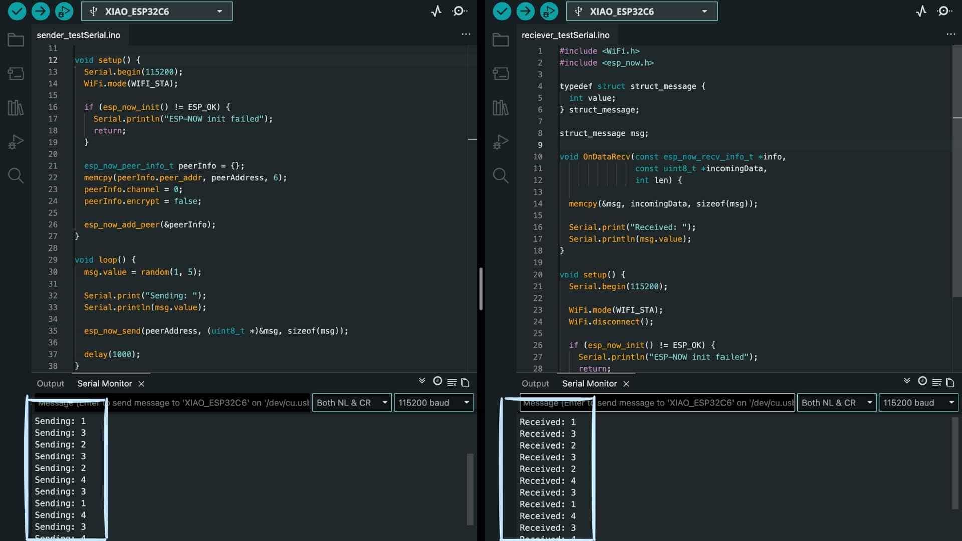
Seeing matching values on both Serial Monitors confirmed:
Sender Side
The logic detects a falling edge (button press), ensuring that each press sends only one signal. This avoids repeated triggering due to button bounce.
Now, instead of sending random values, the board sends a trigger when the button is pressed.
Receiver Side
I used the JQ6500_Serial to control playback.
The initialization sequence was critical and had to be preserved exactly:
mp3Serial.begin(9600, SERIAL_8N1, D7, D6);
delay(3000);

mp3.reset();
delay(1000);

mp3.setSource(MP3_SRC_BUILTIN);
delay(500);

mp3.setVolume(25);
delay(500);
Without these delays, the module behaved inconsistently.
Final Integration
Prompt used on ChatGPT:
Create two simple Arduino programs for two Seeed Studio XIAO ESP32-C6 boards using ESP-NOW.

One board should have a button connected (on pin D8) and send a signal when the button is pressed to the other board using its MAC address 7C:2C:67:64:BA:F8.

The second board should receive this signal and play track 0001.mp3 on a connected JQ6500 using serial communication.

Keep the setup simple, use a baud rate of 115200 for debugging, and ensure that each button press triggers the audio playback clearly.
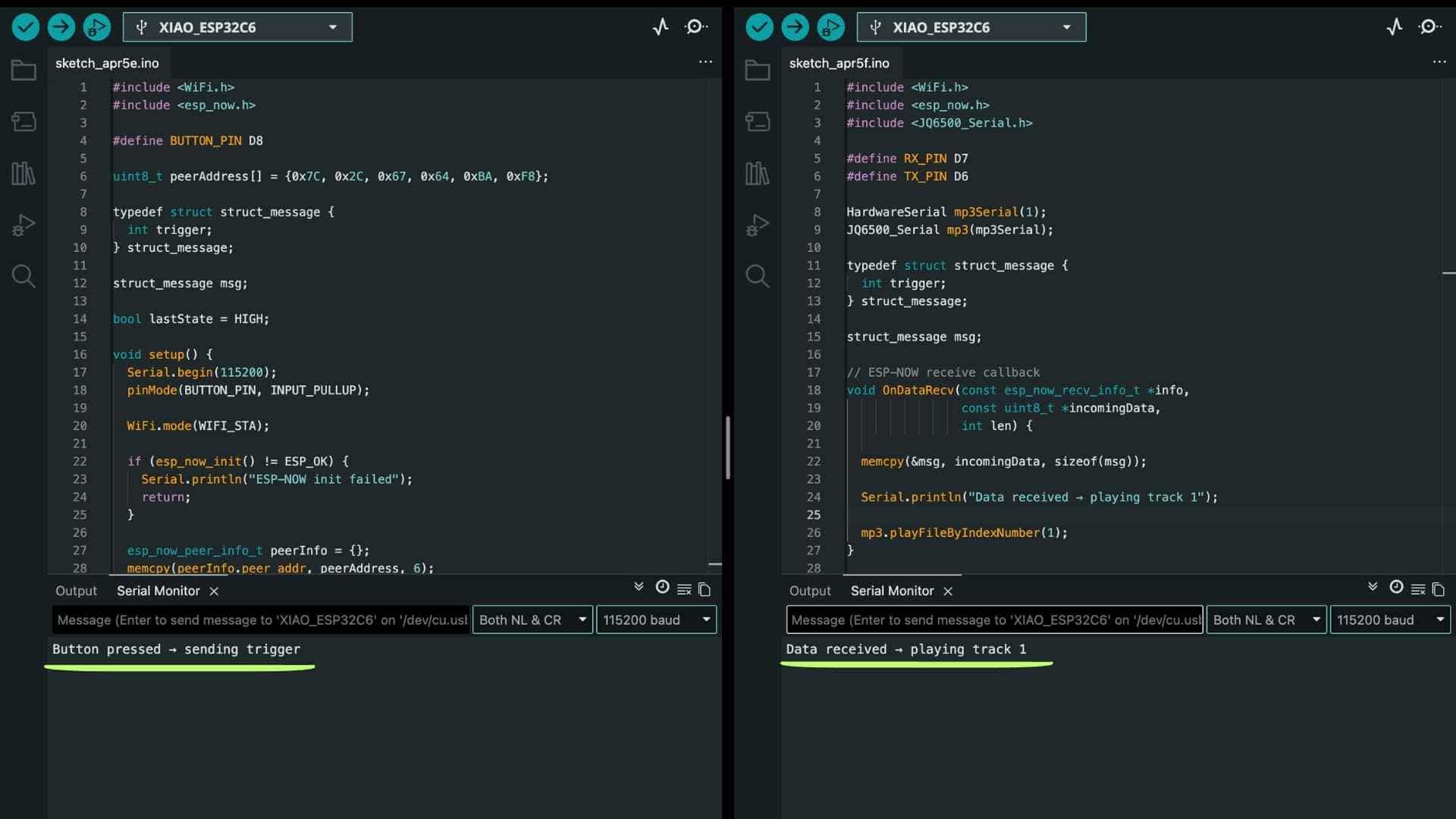
Now the system flow became:
This worked reliably, confirming that all layers - input, communication, and output - were functioning together.
Button Trigger Code for Sender
#include <
WiFi.h> #include <esp_now.h> #define BUTTON_PIN D8 uint8_t peerAddress[] = {0x7C, 0x2C, 0x67, 0x64, 0xBA, 0xF8}; typedef struct struct_message { int trigger; } struct_message; struct_message msg; bool lastState = HIGH; void setup() { Serial.begin(115200); pinMode(BUTTON_PIN, INPUT_PULLUP); WiFi.mode(WIFI_STA); if (esp_now_init() != ESP_OK) { Serial.println("ESP-NOW init failed"); return; } esp_now_peer_info_t peerInfo = {}; memcpy(peerInfo.peer_addr, peerAddress, 6); peerInfo.channel = 0; peerInfo.encrypt = false; esp_now_add_peer(&peerInfo); Serial.println("Sender ready"); } void loop() { bool currentState = digitalRead(BUTTON_PIN); // Detect button press if (lastState == HIGH && currentState == LOW) { msg.trigger = 1; Serial.println("Button pressed → sending trigger"); esp_now_send(peerAddress, (uint8_t *)&msg, sizeof(msg)); delay(300); // debounce } lastState = currentState; }
Playing Track Code for Reciever
#include <
WiFi.h> #include <esp_now.h> #include <JQ6500_Serial.h> #define RX_PIN D7 #define TX_PIN D6 HardwareSerial mp3Serial(1); JQ6500_Serial mp3(mp3Serial); typedef struct struct_message { int trigger; } struct_message; struct_message msg; // ESP-NOW receive callback void OnDataRecv(const esp_now_recv_info_t *info, const uint8_t *incomingData, int len) { memcpy(&msg, incomingData, sizeof(msg)); Serial.println("Data received → playing track 1"); mp3.playFileByIndexNumber(1); } void setup() { Serial.begin(115200); // --- MP3 INIT --- mp3Serial.begin(9600, SERIAL_8N1, RX_PIN, TX_PIN); delay(3000); mp3.reset(); delay(1000); mp3.setSource(MP3_SRC_BUILTIN); delay(500); mp3.setVolume(25); delay(500); Serial.println("MP3 Ready"); // --- ESP-NOW INIT --- WiFi.mode(WIFI_STA); WiFi.disconnect(); if (esp_now_init() != ESP_OK) { Serial.println("ESP-NOW init failed"); return; } esp_now_register_recv_cb(OnDataRecv); Serial.println("Receiver ready"); } void loop() {}
Using a single button to cycle through multiple audio tracks
A single button is used to cycle through four audio tracks. Each press sends a value over ESP-NOW from one XIAO ESP32-C6 board to another, which then plays the corresponding MP3 file using the JQ6500 module.
Prompt used on ChatGPT:
Create two simple Arduino programs for two Seeed Studio XIAO ESP32-C6 boards using ESP-NOW.

One board should have a button on pin D8, where each press sends the next track number (cycling from 1 to 4) to the other board using its MAC address 7C:2C:67:64:BA:F8.

The second board should receive this number and play the corresponding MP3 file (0001.mp3 to 0004.mp3) on a connected JQ6500 using serial communication on pins D7 (RX) and D6 (TX).

Use a baud rate of 115200 for debugging and ensure each button press triggers one track change clearly.
Code for Sender (Board 1 with Button)
#include <
WiFi.h> #include <esp_now.h> #define BUTTON_PIN D8 uint8_t peerAddress[] = {0x7C, 0x2C, 0x67, 0x64, 0xBA, 0xF8}; typedef struct struct_message { int track; } struct_message; struct_message msg; bool lastState = HIGH; int currentTrack = 1; void setup() { Serial.begin(115200); pinMode(BUTTON_PIN, INPUT_PULLUP); WiFi.mode(WIFI_STA); if (esp_now_init() != ESP_OK) { Serial.println("ESP-NOW init failed"); return; } esp_now_peer_info_t peerInfo = {}; memcpy(peerInfo.peer_addr, peerAddress, 6); peerInfo.channel = 0; peerInfo.encrypt = false; esp_now_add_peer(&peerInfo); Serial.println("Sender ready"); } void loop() { bool currentState = digitalRead(BUTTON_PIN); // detect press if (lastState == HIGH && currentState == LOW) { msg.track = currentTrack; Serial.print("Sending track: "); Serial.println(currentTrack); esp_now_send(peerAddress, (uint8_t *)&msg, sizeof(msg)); // move to next track currentTrack++; if (currentTrack > 4) currentTrack = 1; delay(300); // debounce } lastState = currentState; }
Code for Reciever (Board 2 with JQ6500)
#include <
WiFi.h> #include <esp_now.h> #include <JQ6500_Serial.h> // --- MP3 UART PINS --- #define RX_PIN D7 // ESP receives from MP3 TX #define TX_PIN D6 // ESP sends to MP3 RX // --- MP3 SETUP --- HardwareSerial mp3Serial(1); JQ6500_Serial mp3(mp3Serial); // --- DATA STRUCT --- typedef struct struct_message { int track; } struct_message; struct_message msg; // --- ESP-NOW RECEIVE CALLBACK --- void OnDataRecv(const esp_now_recv_info_t *info, const uint8_t *incomingData, int len) { memcpy(&msg, incomingData, sizeof(msg)); Serial.print("Received track: "); Serial.println(msg.track); // Play received track mp3.playFileByIndexNumber(msg.track); } void setup() { Serial.begin(115200); // --- MP3 INITIALIZATION (DO NOT MODIFY) --- mp3Serial.begin(9600, SERIAL_8N1, RX_PIN, TX_PIN); delay(3000); mp3.reset(); delay(1000); mp3.setSource(MP3_SRC_BUILTIN); delay(500); mp3.setVolume(25); delay(500); Serial.println("MP3 Ready"); // --- ESP-NOW SETUP --- WiFi.mode(WIFI_STA); WiFi.disconnect(); if (esp_now_init() != ESP_OK) { Serial.println("ESP-NOW init failed"); return; } esp_now_register_recv_cb(OnDataRecv); Serial.println("Receiver ready"); } void loop() { // nothing required }
Result
2-Way Communication (ESP-NOW)
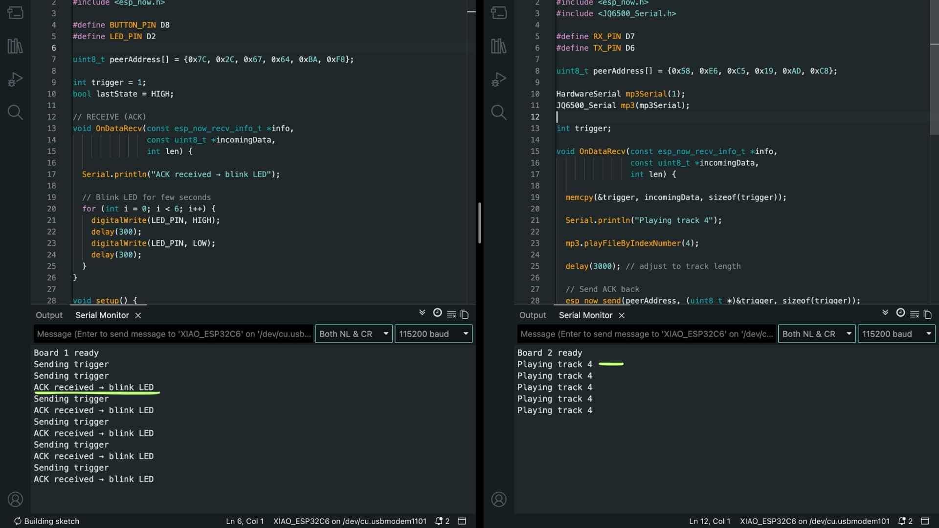
This setup establishes a simple bidirectional communication between two XIAO ESP32-C6 boards using ESP-NOW.
Board 1 (Sender): Detects a button press and sends a trigger signal
Board 2 (Receiver): Receives the trigger, plays an MP3 track, then sends an acknowledgment (ACK) back.
Board 1 (Feedback): Upon receiving the ACK, it blinks an LED for a few seconds.
This creates a minimal but complete loop: Input → Action → Confirmation
Prompt to Generate the Code using ChatGPT
Write code for two XIAO ESP32-C6 boards that talk to each other wirelessly.

On the first board, there is a button on pin D8. When I press it, it should send a signal.

The second board should receive it and play track 4 on an MP3 module.

After playing, it should send a signal back.

On the first board, there is an LED on pin D2. When it receives the signal back, the LED should blink for a few seconds.

Keep the code simple, clear, and easy to follow.

Show both codes separately (one for each board).
Code for Board 1 with Button and LED
#include <
WiFi.h> #include <esp_now.h> #define BUTTON_PIN D8 #define LED_PIN D2 uint8_t peerAddress[] = {0x7C, 0x2C, 0x67, 0x64, 0xBA, 0xF8}; int trigger = 1; bool lastState = HIGH; // RECEIVE (ACK) void OnDataRecv(const esp_now_recv_info_t *info, const uint8_t *incomingData, int len) { Serial.println("ACK received → blink LED"); // Blink LED for few seconds for (int i = 0; i < 6; i++) { digitalWrite(LED_PIN, HIGH); delay(300); digitalWrite(LED_PIN, LOW); delay(300); } } void setup() { Serial.begin(115200); pinMode(BUTTON_PIN, INPUT_PULLUP); pinMode(LED_PIN, OUTPUT); WiFi.mode(WIFI_STA); esp_now_init(); esp_now_peer_info_t peerInfo = {}; memcpy(peerInfo.peer_addr, peerAddress, 6); esp_now_add_peer(&peerInfo); esp_now_register_recv_cb(OnDataRecv); Serial.println("Board 1 ready"); } void loop() { bool currentState = digitalRead(BUTTON_PIN); if (lastState == HIGH && currentState == LOW) { Serial.println("Sending trigger"); esp_now_send(peerAddress, (uint8_t *)&trigger, sizeof(trigger)); delay(300); // debounce } lastState = currentState; }
Code for Board 2 with JQ6500
#include <
WiFi.h> #include <esp_now.h> #include <JQ6500_Serial.h> #define RX_PIN D7 #define TX_PIN D6 uint8_t peerAddress[] = {0x58, 0xE6, 0xC5, 0x19, 0xAD, 0xC8}; HardwareSerial mp3Serial(1); JQ6500_Serial mp3(mp3Serial); int trigger; void OnDataRecv(const esp_now_recv_info_t *info, const uint8_t *incomingData, int len) { memcpy(&trigger, incomingData, sizeof(trigger)); Serial.println("Playing track 4"); mp3.playFileByIndexNumber(4); delay(3000); // adjust to track length // Send ACK back esp_now_send(peerAddress, (uint8_t *)&trigger, sizeof(trigger)); } void setup() { Serial.begin(115200); // MP3 INIT mp3Serial.begin(9600, SERIAL_8N1, RX_PIN, TX_PIN); delay(3000); mp3.reset(); delay(1000); mp3.setSource(MP3_SRC_BUILTIN); delay(500); mp3.setVolume(25); delay(500); WiFi.mode(WIFI_STA); esp_now_init(); esp_now_peer_info_t peerInfo = {}; memcpy(peerInfo.peer_addr, peerAddress, 6); esp_now_add_peer(&peerInfo); esp_now_register_recv_cb(OnDataRecv); Serial.println("Board 2 ready"); } void loop() {}
Result
Key Code Components
1. Wi-Fi Mode
WiFi.mode(WIFI_STA);
What it does: Sets the ESP to station mode, enabling use of its Wi-Fi radio for communication.
Why required: ESP-NOW operates over the Wi-Fi hardware at the MAC layer. Without WIFI_STA, ESP-NOW either fails to initialize or behaves inconsistently.
2. Initialize ESP-NOW
esp_now_init();
What it does: Initializes the ESP-NOW protocol stack.
Why required: Without initialization, no ESP-NOW functions (send/receive) will work. This is the entry point for the protocol.
3. Peer Configuration (MAC Address)
esp_now_add_peer(...);
What it does: Registers another ESP device (using its MAC address) as a communication peer.
Why required: ESP-NOW does not broadcast by default in your setup. It needs to know exactly where to send data.
4. Data Structure
typedef struct {
  int command;
} Message;
What it does: Defines the format of the data packet being sent.
Why required: ESP-NOW sends raw bytes. A struct ensures both devices interpret the data consistently.
5. Sending Data
esp_now_send(receiverMAC, (uint8_t *)&msg, sizeof(msg));
What it does: Transmits the structured data (msg) to the specified receiver.
Why required: This is the actual communication call—without it, no data leaves the sender.
6. Receive Callback
esp_now_register_recv_cb(onReceive);
What it does: Registers a function (onReceive) that is automatically triggered when data arrives.
Why required: ESP-NOW is event-driven. Without this, incoming data is never processed.
7. Data Extraction
memcpy(&incomingMsg, incomingData, sizeof(incomingMsg));
What it does: Copies raw bytes into a structured format (incomingMsg).
Why required: ESP-NOW delivers raw data. This step converts it into usable variables.
8. Action Logic
if (incomingMsg.command == 4) {
  playTrack4();
}
What it does: Interprets the received command and executes the corresponding action.
Why required: ESP-NOW only delivers data—the meaning and action must be defined by you.
9. Extended Data Structure
typedef struct {
  int type;     // 0 = command, 1 = ACK
  int command;  // e.g., play track 4
} Message;
What it does:Adds a message type field to distinguish between: commands, acknowledgments.
Why required: In two-way communication, devices both send and receive. This prevents confusion between instruction and confirmation.
10. Receiver Sends ACK
if (msg.type == 0) {
  playTrack4();

  ackMsg.type = 1;
  ackMsg.command = msg.command;

  esp_now_send(senderMAC, (uint8_t *)&ackMsg, sizeof(ackMsg));
}
What it does: Sends a confirmation message back to the sender after executing the command.
Why required: Provides feedback and reliability—the sender knows the action was completed.
11. Sender Receives ACK
if (msg.type == 1) {
  blinkLED();  // confirmation feedback
}
What it does: Checks if the received message is an ACK and triggers feedback (e.g., LED).
Why required: Links system response to actual execution, not just button press—this makes the interaction truthful.
Reflection
This week felt incremental, like most weeks. We've been in electronics for a while now, and I think I've slowly picked up a few things along the way. I just approached it step by step, started from the basics, and tried to work toward what I had in mind.
Before jumping into the actual functionality, I just wanted to check if the two boards were even talking to each other. I already knew both boards worked fine individually from previous weeks, so I didn't need to test that again. I just sent a random number between them and watched the serial monitor. Once I could see data passing through, that was enough to move forward.
From there I started building it up gradually. First, a button press on board 1 plays a track on board 2. Then I tried playing all the tracks in order with one button. Then made it so every press plays the next track. Once that felt solid, I moved into two-way communication. One button, one track, and after it plays, an LED on board 1 blinks for a bit. That's where I ended the week... Did I??

Adding a Third Node to the System
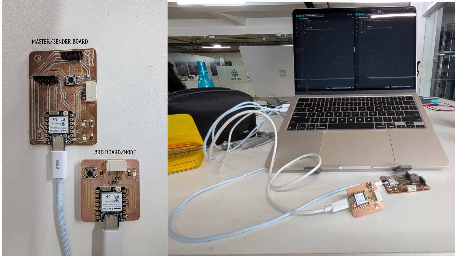
Up to this point, the system consisted of a sender board (master) and a single receiver node. The sender knew only one device and sent all communication to that node.
When introducing a third board, the goal was not to redesign the system, but simply to extend it so that the sender could communicate with more than one receiver.
The third node came from the networking class hello.ESP32C6
Understanding the Change
ESP-NOW does not create a “network” in the traditional sense. There is no pairing process or central router. Instead, each device communicates directly using MAC addresses.
A simple way to think about this is:
With this model, adding a new node becomes straightforward.
Before Adding Node 3
Initially, the sender board was configured to communicate only with Node 2.
In code, this meant:
Conceptually:
Sender → Node 2
Adding Node 3
Step 1 - Getting the MAC Address
The first step was to retrieve the MAC address of Node 3 using a simple Wi-Fi sketch. This address uniquely identifies the board.
58:E6:C5:19:B9:BC
This was then converted into a format usable in code:
uint8_t macNode3[] = {0x58, 0xE6, 0xC5, 0x19, 0xB9, 0xBC};
Step 2 - Registering Node 3 as a Peer
To allow communication, the sender board must explicitly know about the receiver.
memcpy(peerInfo.peer_addr, macNode3, 6);
esp_now_add_peer(&peerInfo);
This step effectively means:
The sender board now recognizes Node 3 as a valid receiver and is allowed to send data to it.
At this point, the sender has two known peers:
Step 3 - Sending Data to Node 3
Once the peer is registered, sending data is simply a matter of specifying the correct MAC address:
esp_now_send(macNode3, (uint8_t *)&msg, sizeof(msg));
This directs the message specifically to Node 3.
Step 4 - Receiving on Node 3
On the receiver side, Node 3 is always listening for incoming data using a callback function:
esp_now_register_recv_cb(OnDataRecv);
When a message arrives, it is processed inside this function.
To ensure that each node only responds to messages intended for it, a simple check is used:
if (msg.targetID != NODE_3) return;
This prevents unintended behavior when multiple nodes are present.
System After Adding Node 3
The system now operates with one sender and multiple receivers:
Sender → Node 2
       → Node 3
The sender board decides which node should act and sends the message accordingly.
Code:
Prompt used on ChatGPT
Create two simple Arduino programs for two Seeed Studio XIAO ESP32-C6 boards using ESP-NOW.

One board should act as a sender and continuously send a simple message every 2 seconds to another board using its MAC address 58:E6:C5:19:B9:BC.

The second board should receive the message and print it to the Serial Monitor.

Keep it minimal for debugging:

Use WiFi station mode

Baud rate 115200

Print send status on sender and receive confirmation on receiver

Use a simple struct with an integer value


The goal is to verify basic ESP-NOW communication between the two boards.
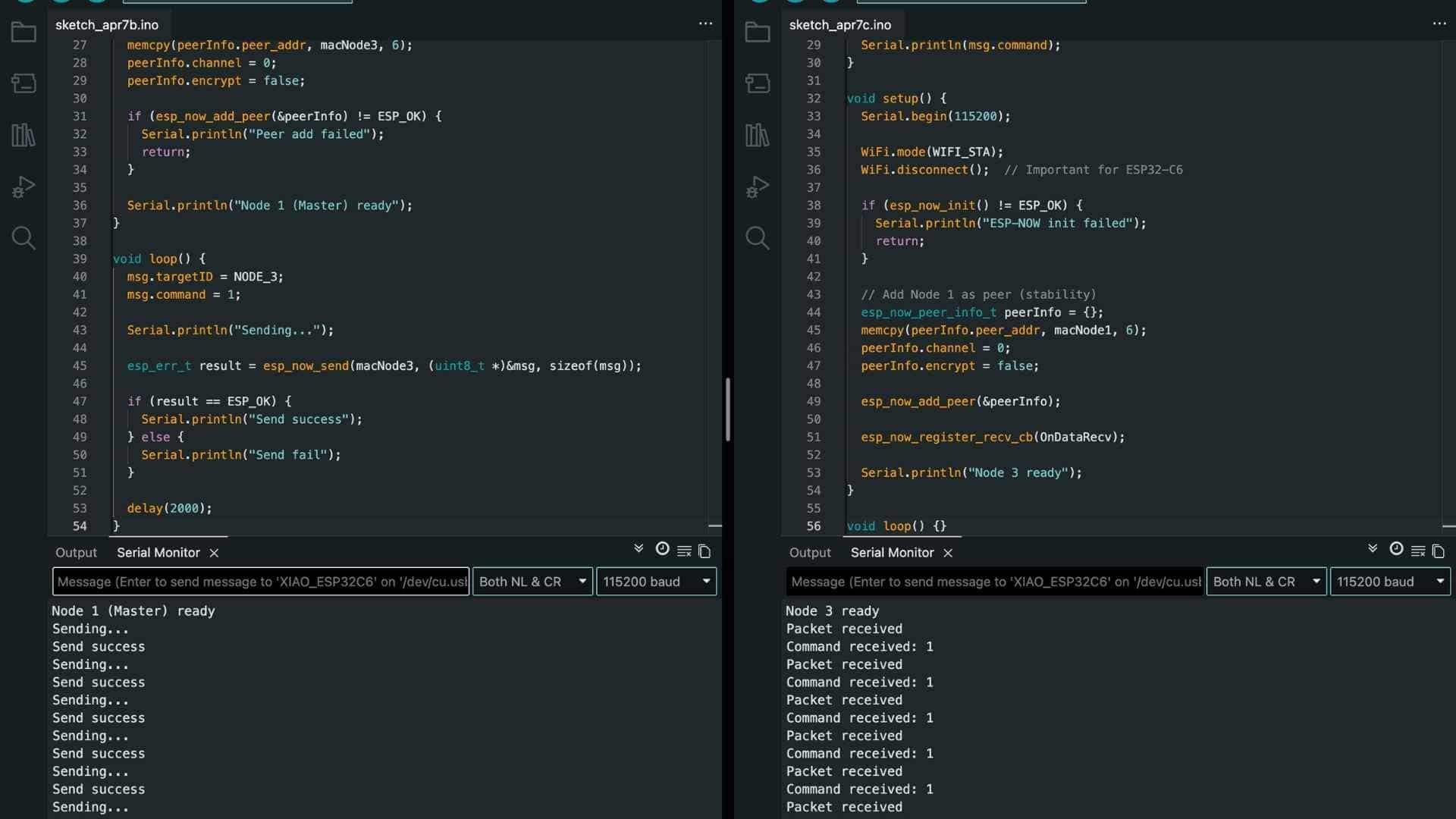
Node 1 - Master/Sender Code
#include <
WiFi.h> #include <esp_now.h> #define NODE_3 3 // Node 3 MAC uint8_t macNode3[] = {0x58, 0xE6, 0xC5, 0x19, 0xB9, 0xBC}; typedef struct { int targetID; int command; } Message; Message msg; void setup() { Serial.begin(115200); WiFi.mode(WIFI_STA); if (esp_now_init() != ESP_OK) { Serial.println("ESP-NOW init failed"); return; } esp_now_peer_info_t peerInfo = {}; memcpy(peerInfo.peer_addr, macNode3, 6); peerInfo.channel = 0; peerInfo.encrypt = false; if (esp_now_add_peer(&peerInfo) != ESP_OK) { Serial.println("Peer add failed"); return; } Serial.println("Node 1 (Master) ready"); } void loop() { msg.targetID = NODE_3; msg.command = 1; Serial.println("Sending..."); esp_err_t result = esp_now_send(macNode3, (uint8_t *)&msg, sizeof(msg)); if (result == ESP_OK) { Serial.println("Send success"); } else { Serial.println("Send fail"); } delay(2000); }
Node 3 - Reciever Code
#include <
WiFi.h> #include <esp_now.h> #define NODE_3 3 typedef struct { int targetID; int command; } Message; // Replace with your Node 1 MAC if needed uint8_t macNode1[] = {0x58, 0xE6, 0xC5, 0x19, 0xAD, 0xC8}; void OnDataRecv(const esp_now_recv_info_t *info, const uint8_t *incomingData, int len) { Serial.println("Packet received"); Message msg; memcpy(&msg, incomingData, sizeof(msg)); if (msg.targetID != NODE_3) { Serial.println("Not for me"); return; } Serial.print("Command received: "); Serial.println(msg.command); } void setup() { Serial.begin(115200); WiFi.mode(WIFI_STA); WiFi.disconnect(); // Important for ESP32-C6 if (esp_now_init() != ESP_OK) { Serial.println("ESP-NOW init failed"); return; } // Add Node 1 as peer (stability) esp_now_peer_info_t peerInfo = {}; memcpy(peerInfo.peer_addr, macNode1, 6); peerInfo.channel = 0; peerInfo.encrypt = false; esp_now_add_peer(&peerInfo); esp_now_register_recv_cb(OnDataRecv); Serial.println("Node 3 ready"); } void loop() {}
Key Takeaway
Adding a third node did not require a new communication system. The only changes were:
In essence:
Adding a new node is simply adding a new “contact” and choosing when to communicate with it.

Multi-Node ESP-NOW Communication Test
More Debugging
Task: verify that the sender (master) can talk to both receiver nodes simultaneously. No sequencing, no ACKs yet.
Button (Master)
   ↓
Node 2 reacts
Node 3 reacts
This validates:
Message Definition (Same on all boards)
  typedef struct {
  int targetID;
  int command;
} Message;
IDs
#define NODE_2 2
#define NODE_3 3
Node 1 - Master (Sender Board)
What it does:
#include <
WiFi.h> #include <esp_now.h> #define BUTTON_PIN D8 #define NODE_2 2 #define NODE_3 3 uint8_t macNode2[] = {0x7C, 0x2C, 0x67, 0x64, 0xBA, 0xF8}; uint8_t macNode3[] = {0x58, 0xE6, 0xC5, 0x19, 0xB9, 0xBC}; typedef struct { int targetID; int command; } Message; Message msg; bool lastState = HIGH; void setup() { Serial.begin(115200); pinMode(BUTTON_PIN, INPUT_PULLUP); WiFi.mode(WIFI_STA); if (esp_now_init() != ESP_OK) { Serial.println("ESP-NOW init failed"); return; } // Add Node 2 esp_now_peer_info_t peer2 = {}; memcpy(peer2.peer_addr, macNode2, 6); peer2.channel = 0; peer2.encrypt = false; esp_now_add_peer(&peer2); // Add Node 3 esp_now_peer_info_t peer3 = {}; memcpy(peer3.peer_addr, macNode3, 6); peer3.channel = 0; peer3.encrypt = false; esp_now_add_peer(&peer3); Serial.println("Master ready"); } void loop() { bool currentState = digitalRead(BUTTON_PIN); if (lastState == HIGH && currentState == LOW) { Serial.println("Sending to Node 2"); msg.targetID = NODE_2; msg.command = 1; esp_now_send(macNode2, (uint8_t *)&msg, sizeof(msg)); Serial.println("Sending to Node 3"); msg.targetID = NODE_3; msg.command = 1; esp_now_send(macNode3, (uint8_t *)&msg, sizeof(msg)); delay(300); } lastState = currentState; }
Node 2 (Audio Board - Simplified for Test)
For now, NOT playing audio. Just printing.
#include <
WiFi.h> #include <esp_now.h> #define NODE_2 2 uint8_t macNode1[] = {0x58, 0xE6, 0xC5, 0x19, 0xAD, 0xC8}; typedef struct { int targetID; int command; } Message; void OnDataRecv(const esp_now_recv_info_t *info, const uint8_t *incomingData, int len) { Serial.println("RAW PACKET ARRIVED"); Message msg; memcpy(&msg, incomingData, sizeof(msg)); Serial.print("targetID: "); Serial.println(msg.targetID); if (msg.targetID != NODE_2) { Serial.println("Not for Node 2"); return; } Serial.println("Node 2 → command received"); } void setup() { Serial.begin(115200); WiFi.mode(WIFI_STA); WiFi.disconnect(); if (esp_now_init() != ESP_OK) { Serial.println("ESP-NOW init failed"); return; } // Add Master as peer esp_now_peer_info_t peer = {}; memcpy(peer.peer_addr, macNode1, 6); peer.channel = 0; peer.encrypt = false; esp_now_add_peer(&peer); esp_now_register_recv_cb(OnDataRecv); Serial.println("Node 2 ready"); } void loop() {}
Node 3 (LED Board)
#include <
WiFi.h> #include <esp_now.h> #define NODE_3 3 #define LED_PIN D0 uint8_t macNode1[] = {0x58, 0xE6, 0xC5, 0x19, 0xAD, 0xC8}; typedef struct { int targetID; int command; } Message; void OnDataRecv(const esp_now_recv_info_t *info, const uint8_t *incomingData, int len) { Serial.println("Packet received"); Message msg; memcpy(&msg, incomingData, sizeof(msg)); if (msg.targetID != NODE_3) return; Serial.println("Node 3 → blinking LED"); digitalWrite(LED_PIN, HIGH); delay(300); digitalWrite(LED_PIN, LOW); } void setup() { Serial.begin(115200); pinMode(LED_PIN, OUTPUT); WiFi.mode(WIFI_STA); WiFi.disconnect(); esp_now_init(); // Add Master as peer esp_now_peer_info_t peer = {}; memcpy(peer.peer_addr, macNode1, 6); peer.channel = 0; peer.encrypt = false; esp_now_add_peer(&peer); esp_now_register_recv_cb(OnDataRecv); Serial.println("Node 3 ready"); } void loop() {}
On button press:
Master: Button pressed → sending to both nodes
Node 2: Node 2 → command received
Node 3: Node 3 → blinking LED
Code modified to play track 4 on Node/Board 2
#include <
WiFi.h> #include <esp_now.h> #include#define NODE_2 2 #define RX_PIN D7 #define TX_PIN D6 uint8_t macNode1[] = {0x58, 0xE6, 0xC5, 0x19, 0xAD, 0xC8}; HardwareSerial mp3Serial(1); JQ6500_Serial mp3(mp3Serial); // Match struct from master typedef struct { int targetID; int command; } Message; void OnDataRecv(const esp_now_recv_info_t *info, const uint8_t *incomingData, int len) { Serial.println("Packet received"); Message msg; memcpy(&msg, incomingData, sizeof(msg)); // Only respond if meant for Node 2 if (msg.targetID != NODE_2) return; Serial.println("Playing track 4"); mp3.playFileByIndexNumber(4); } void setup() { Serial.begin(115200); // --- MP3 INIT (KEEP EXACT) --- mp3Serial.begin(9600, SERIAL_8N1, RX_PIN, TX_PIN); delay(3000); mp3.reset(); delay(1000); mp3.setSource(MP3_SRC_BUILTIN); delay(500); mp3.setVolume(25); delay(500); Serial.println("MP3 Ready"); // --- ESP-NOW --- WiFi.mode(WIFI_STA); WiFi.disconnect(); if (esp_now_init() != ESP_OK) { Serial.println("ESP-NOW init failed"); return; } esp_now_peer_info_t peer = {}; memcpy(peer.peer_addr, macNode1, 6); peer.channel = 0; peer.encrypt = false; esp_now_add_peer(&peer); esp_now_register_recv_cb(OnDataRecv); Serial.println("Node 2 ready"); } void loop() {}
Group Assignment
As a group, the goal is simpler but stricter: make two different projects talk to each other. That means agreeing on how we send data, making sure both sides understand it, and actually getting a message to go from one system to another reliably.
Reflection
This assignment demonstrated that networking is not limited to communication between two microcontrollers and that it can also bridge multiple systems, protocols, and independently developed projects. By integrating Nadec's custom PCB with my two-board audio system, we successfully combined Wi-Fi (TCP) and ESP-NOW into a single communication pipeline.
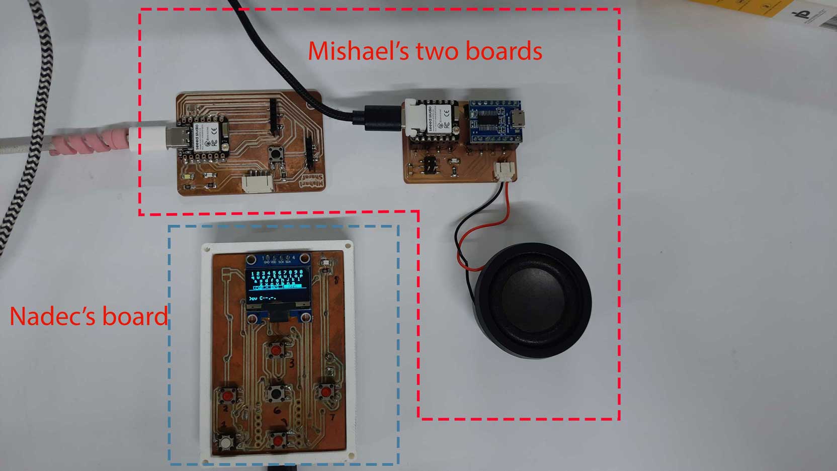
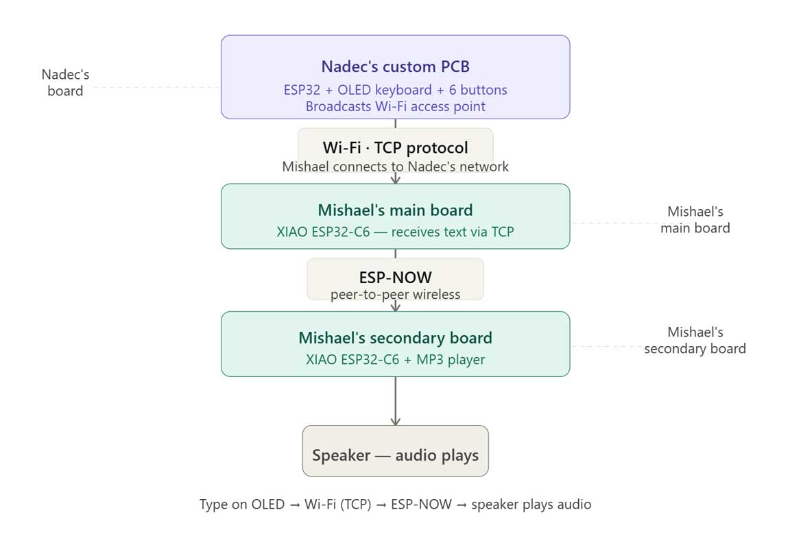
The project showed how data can seamlessly travel across different devices and protocols: from user input on an OLED interface, through a TCP connection, into an ESP32-C6, and finally via ESP-NOW to trigger audio playback on a secondary board. This modular approach allowed each board to perform a dedicated task while working together as one cohesive system.
Beyond meeting the week's objective, the assignment reinforced the importance of interoperability, protocol selection, and collaborative system integration. It demonstrated how independently developed hardware can be connected into a larger ecosystem, a principle that extends well beyond this exercise and is fundamental to building scalable embedded systems.
For detailed documentation, visit group Assignment page.Source Files
Mac Address
Debugging Board 1 and 2
Button to Play Track
Multiple Tracks with Single Button
Two Way Communication with ESP-NOW
Debugging Board 1 and 3
Multi-Node with 3 boards