Week 10: Output Devices
This week focuses on working with output devices and understanding how microcontrollers interact with the physical world by producing visible or measurable responses.
As part of the group assignment, we will measure the power consumption of an output device to better understand its electrical behavior and requirements. For the individual assignment, the task is to integrate an output device into a microcontroller board that I have designed and program it to perform a specific function.
This week builds on previous input and sensing work, shifting the focus from reading data to generating controlled outputs.
This week was guided by Saheen and Sibin.
Group Assignment Reflection
This group assignment helped me understand how power consumption can be measured in a practical electronics workflow. Rather than relying on theoretical values from datasheets, we used a bench power supply and a digital multimeter to measure the actual current drawn by output devices and calculate their power consumption.
To determine the power consumed by a device, we measured the supply voltage and current and applied the equation:
Power (W) = Voltage (V) × Current (A)
For the NeoPixel test:
Therefore:
Power = 5 × 0.0337 = 0.1685 W
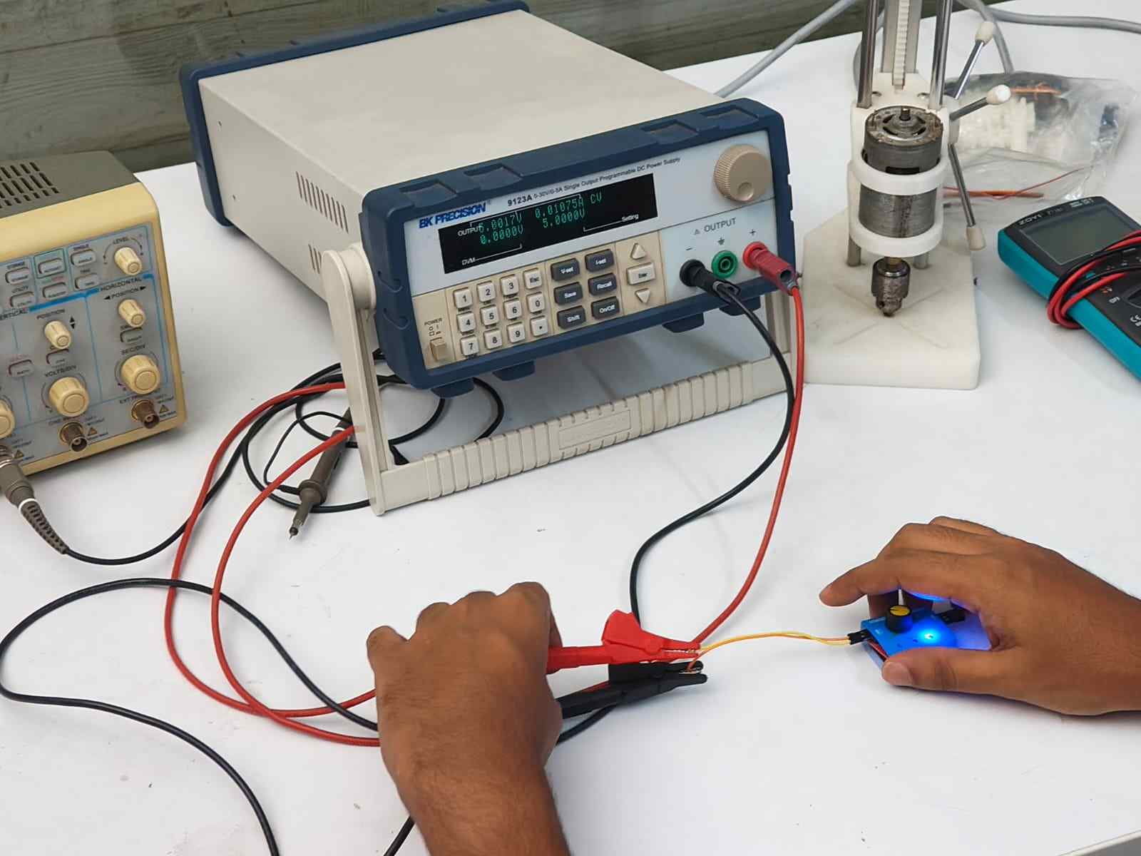
Similarly, for the stepper motor:
Therefore:
Power = 5 × 0.011 = 0.055 W
Through this exercise, I learned how to correctly measure current by connecting the multimeter in series with the circuit and how current measurements can be used to calculate power consumption. I also understood how these values can be used to estimate battery requirements and overall energy usage in a project. This is particularly useful when designing embedded systems and portable devices, where selecting an appropriate power supply and battery capacity is an important part of the design process.
Output Devices
Output devices are components that take signals from a microcontroller and do something in the physical world. They're how your circuit "acts" on decisions made by the code.
Without output devices your microcontroller just processes data with no visible or physical result, nothing actually happens.
How They Work
Microcontroller → Signal → Output device → Physical effect
For example:
XIAO sends PWM signal → Servo receives it → Arm moves to 90°
Types of Output Devices
| Type | Example | Input |
|---|---|---|
| Mechanical | Servo, DC motor | PWM signal |
| Visual | LED, display | Digital/analog signal |
| Audio | Speaker, buzzer | PWM/analog signal |
| Communication | Relay, MOSFET | Digital signal |
Why We Need Them
Actuators
All actuators are output devices
but
Not all output devices are actuators
An actuator is specifically a device that converts energy into physical motion or action.
Are All Output Devices Actuators? No,here's the distinction:
| Output Device | Actuator? | Why |
|---|---|---|
| Servo motor | Yes | converts electrical energy into mechanical motion |
| DC motor | Yes | converts electrical energy into rotation |
| LED | No | produces light, not motion or physical action |
| Speaker | Borderline | moves a membrane to produce sound, technically mechanical |
| Display | No | produces light/image, no physical action |
| Relay | Yes | physically switches a circuit open or closed |
| Buzzer | Borderline | vibrates to produce sound, mechanical movement |
PWM (Pulse Width Modulation)

PWM is a way of controlling output devices by switching a signal on and off really fast. The ratio of on-time to off-time is called the duty cycle.
100% duty    50% duty     25% duty
┌┐┌┐┌┐┌┐    ┌┐  ┌┐  ┌┐   ┌┐    ┌┐
┘└┘└┘└┘└    ┘└──┘└──┘└   ┘└────┘└────
Duty Cycle
Duty cycle = (ON time / Total period) x 100%
Higher duty cycle = more power to the device.
For a Servo Motor
Servos use a 50Hz PWM signal (20ms period). The pulse width controls the angle:
1ms   → 0°    (full left)
1.5ms → 90°   (center)
2ms   → 180°  (full right)
The servo reads the pulse width and moves to the matching angle.
| Device | PWM controls |
|---|---|
| Servo | Angle |
| LED | Brightness |
| DC Motor | Speed |
| Buzzer | Tone |
Servo Motor
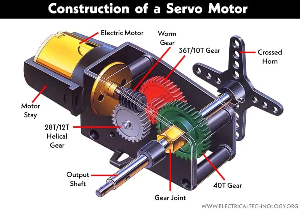
Servo Motor: Types, Construction, Working, and Applications
MG90S Micro Servo Motor
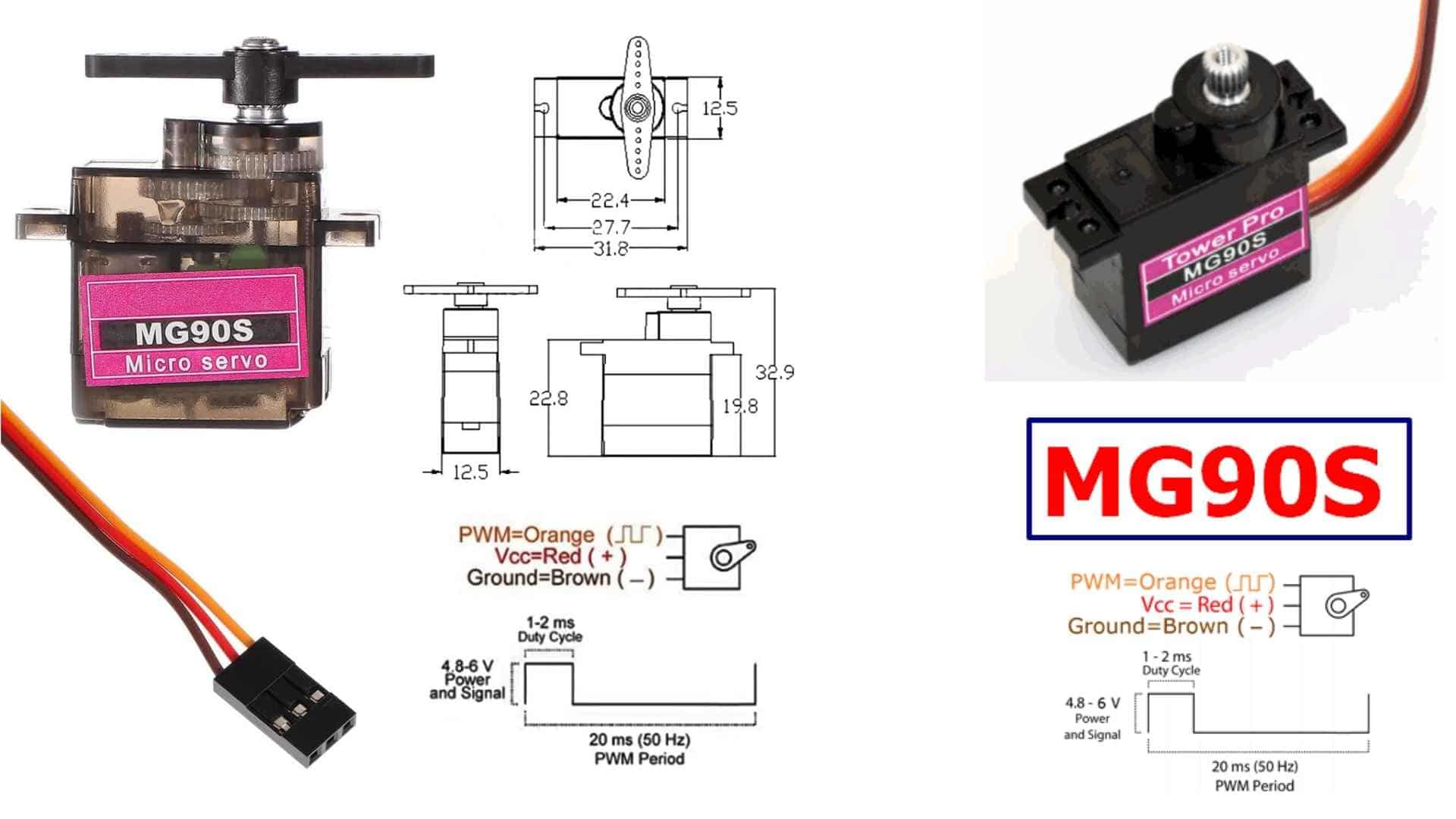
The MG90S is a small, metal gear servo motor used for controlled movement. It is compact, precise, and strong for its size, which makes it useful in systems where motion needs to be intentional rather than continuous. It does not spin freely. Instead, it moves to a specific position and holds it.
DatasheetServo PWM

Wiring
The servo uses three wires.
Brown connects to ground.
Red connects to power, usually 5 volts.
Orange carries the control signal.
Once powered, the motor responds to signals sent through the control wire.
Characteristics
It operates around 5 volts.
It can rotate from 0 to 180 degrees.
It produces enough torque for small mechanical tasks.
The metal gears make it more durable under repeated use.
The actual strength depends on how the force is applied. A shorter lever arm increases its ability to lift or resist load.
Dimensions
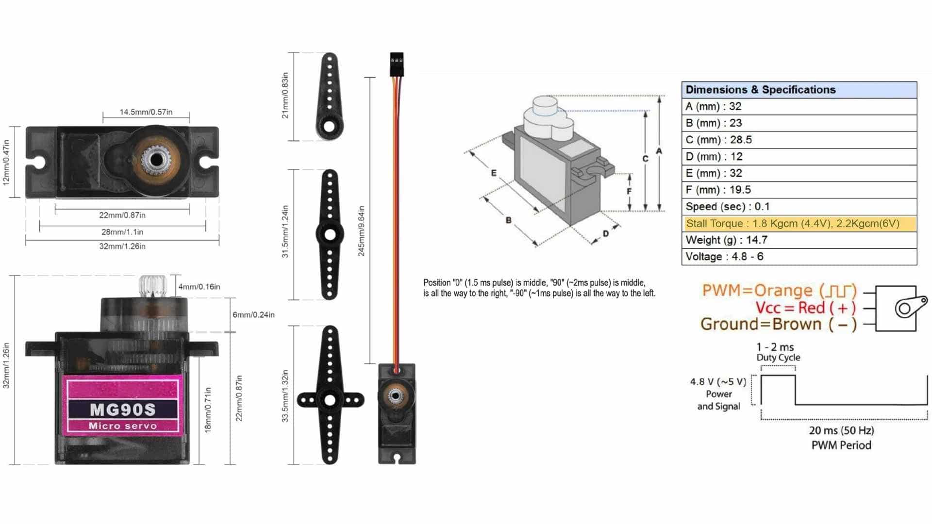
Its small size allows it to be embedded into compact assemblies, where movement is part of the interaction rather than an external addition.
reference usedRole of the Servo in My Project
What is a Servo Motor and What Does It Do?In my project, the servo motor acts as a controlled gate that regulates when a coin is allowed to enter the system.
It is not always open. It stays closed by default, holding a clear boundary between input and storage.
When a child selects a denomination, the system becomes active and waits.
The IR sensor checks if a coin is actually present in the slot.
Only when this condition is met does the servo respond.
The servo then rotates to open a flap. This is the moment of acceptance.
The coin is allowed to pass through, not instantly, but in a guided and slowed manner.
This delay makes the transition visible and intentional.
After the coin moves into storage, the servo returns to its closed position.
The system resets, ready for the next interaction.
Locking Mechanism
To prevent access to saved coins before the goal is reached, the system needs a physical lock on the coin chamber door. Two approaches were considered.
Solenoid - An electromagnetic actuator whose plunger acts directly as a bolt. Clean and purpose-built, but requires a transistor driver and flyback diode, adding cost and PCB complexity.
Servo - A small SG90 drives a 3D printed sliding bolt via a simple linkage. When the goal is reached, the servo rotates, the bolt retracts, and the door swings open. Since a servo is already used for the coin flap, no new components or wiring approaches are needed. The bolt carries no coin weight, coins rest on the fixed chamber floor, keeping the load comfortably within the SG90's torque range.
Both achieve the same function. The solenoid is more direct; the servo is simpler to integrate and more accessible in a fab lab context.
Solenoid
Solenoids are basically electromagnets: they are made of a coil of copper wire with an armature (a slug of metal) in the middle. When the coil is energized, the slug is pulled into the center of the coil. This makes the solenoid able to pull (from one end) or push (from the other).
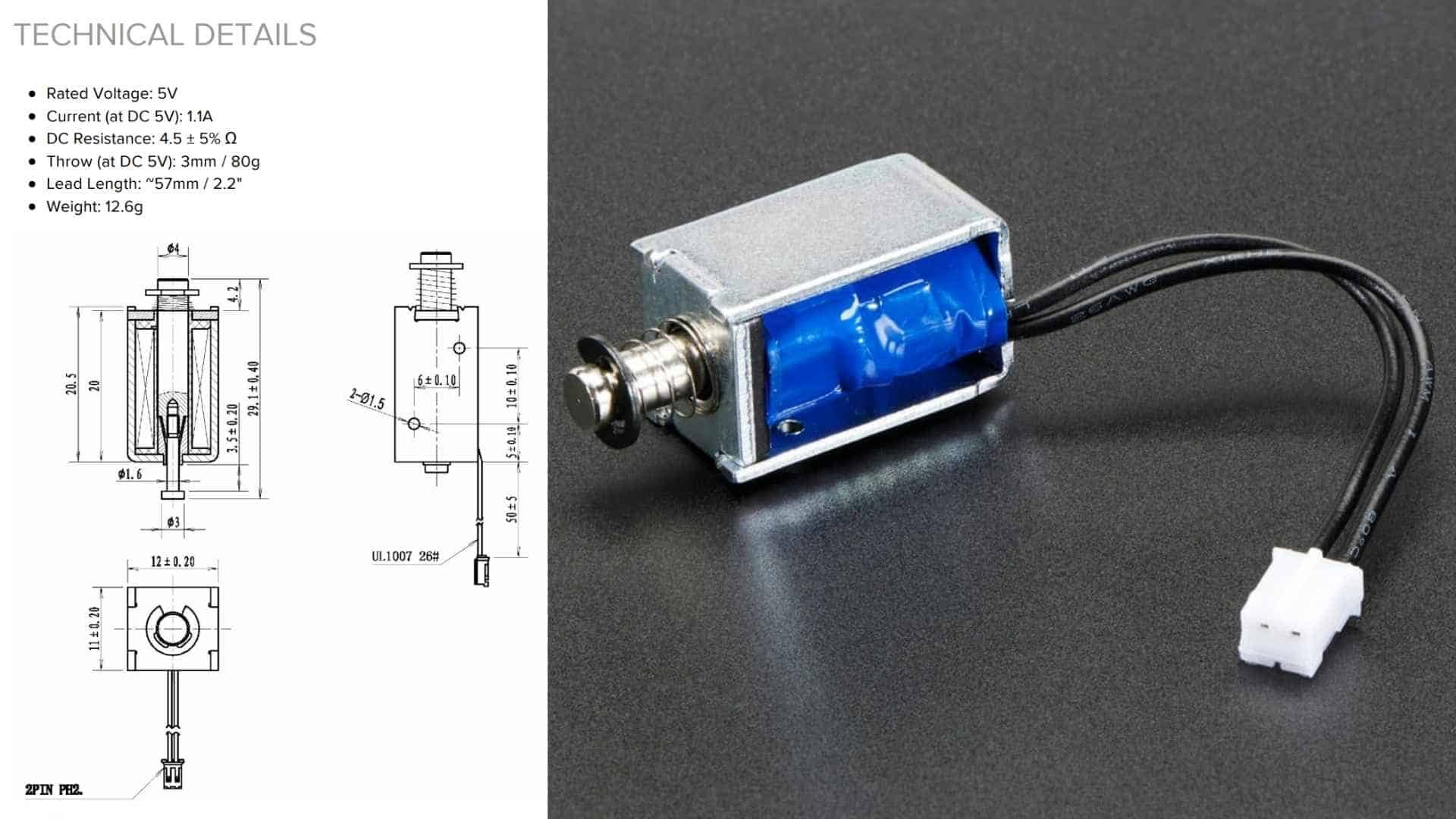
How a Solenoid Works
Solenoid Working PrincipleA solenoid is a coil of wire wrapped around a hollow tube. When electric current flows through the coil, it generates a magnetic field inside the tube. This magnetic field attracts a metal plunger sitting inside or next to the tube, pulling it inward with force.
When the current is switched off, the magnetic field collapses and the plunger returns to its original position, either by gravity or a small return spring.
The result is a simple linear motion:
Current on → plunger pulls in.
Current off → plunger pushes out.
This push and pull is what makes it useful as a locking mechanism, the plunger acts directly as a bolt, no rotating parts, no linkages needed.
The strength of the force depends on the amount of current and the number of coils. More current, stronger pull.
MP3 module and Speaker
JQ6500 MP3 Player Module Datasheet Reference Material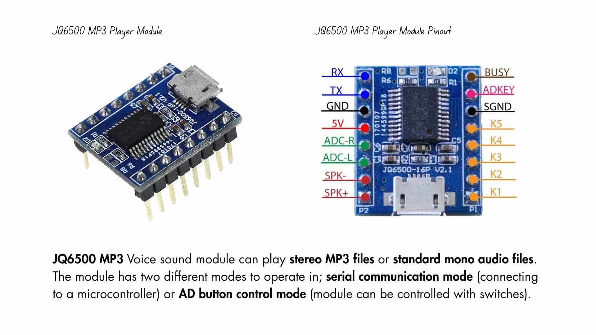
JQ6500 MP3 is a hardware decoder providing serial MP3 chip, perfectly integrating MP3 and WMV. Meanwhile, the software supports TF card driver, spi flash update on the computer, and FAT16, FAT32 file system. Through simple serial commands, it can execute music playing. Easy-to-use without cumbersome underlying operations, stability and reliability are the most important features of this product. Also the chip is uniquely customized as a low-cost solution for specific voice playing field.
Features and Specifications of JQ6500 MP3 Player Module
This section mentions some of the features and specifications of the JQ6500 MP3 player
Connecting JQ6500 MP3 Player Module to an MCU/MPU
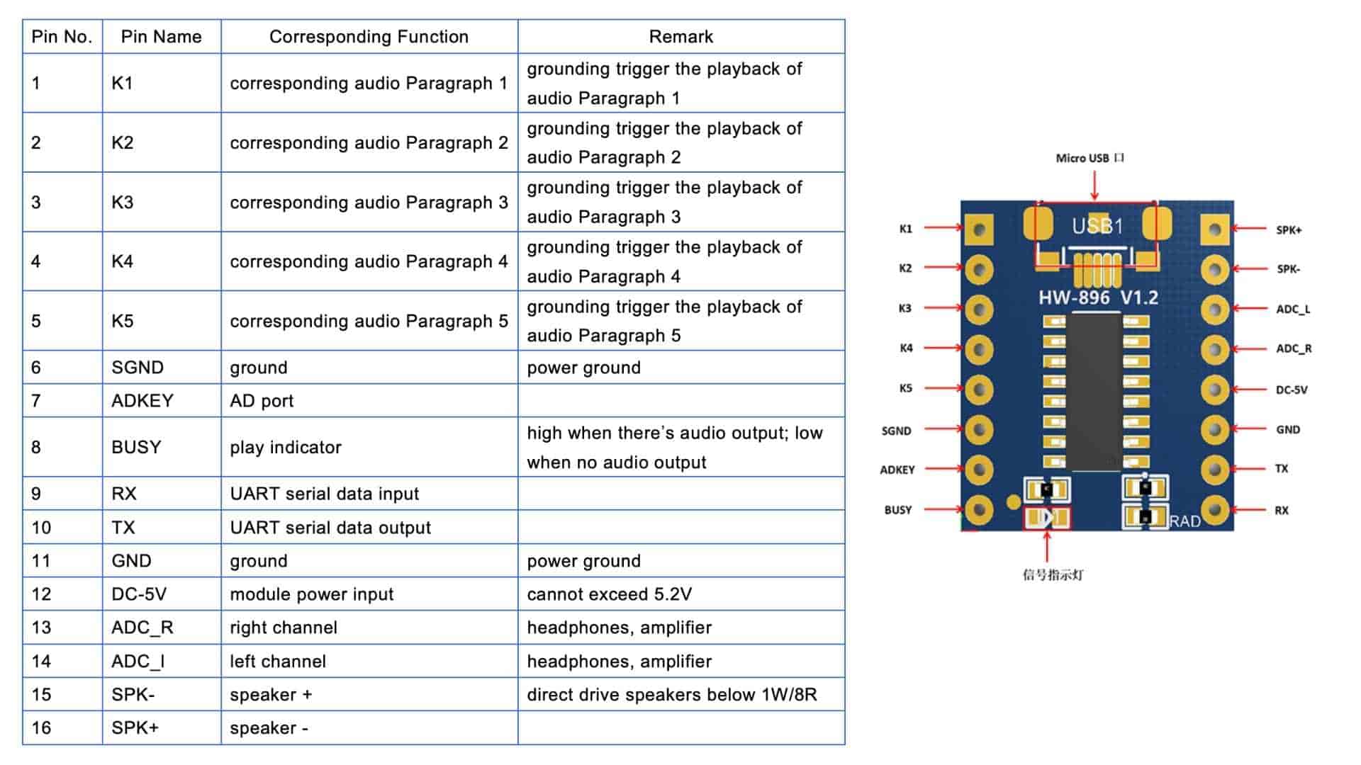
There are two modes by which the JQ6500 module can be controlled. Using buttons or through a microcontroller. Connecting the JQ6500 module is pretty easy. K pins(K1, K2, K3, K4, K5) are pins for the ground trigger to play the defined audio for that port. The JQ6500 module can communicate to an MCU/MPU via UART communication. The RX TX pins on the module are to be connected to the TX and RX pins of the MCU/MPU, respectively. The speaker is connected to the SPK - and SPK + pins on the board.
Libraries and softwares to be installed: JQ6500 Serial, Music update tool software can be downloaded and used to update the soundtracks by connecting a mini USB to the computer.
Application of JQ6500 MP3 Player Module
Here are some of the applications of the JQ6500 MP3 player:
Individually Addressable RGB LEDs (NeoPixel LEDs)
A NeoPixel is a brand of individually addressable RGB LEDs popularized by Adafruit Industries. Unlike standard LEDs that require a separate pin for every color and every light, hundreds of NeoPixels can be controlled using just a single data pin from a microcontroller like an Arduino or ESP32.
Role in this project
In this savings tracker, the NeoPixel strip replaces what would typically be an OLED screen. The goal was to keep the feedback simple and visual, something a kid can glance at and immediately understand without reading any numbers or text.
The strip has 8 LEDs, each representing roughly 12.5% of the savings goal. As coins are inserted, the strip fills up from left to right, shifting color from red (just getting started) through yellow (halfway there) to green (goal reached). This makes progress feel intuitive and rewarding at a glance.
The strip also has two distinct states:
| State | Trigger | Strip Behaviour |
|---|---|---|
| Coin detected | New coin inserted | Breathing pulse (all LEDs) |
| Progress update | After coin is registered | Fill left to right, red → yellow → green |
The breathing pulse gives immediate physical feedback that the coin was registered before the progress fill kicks in, important for a young user who might otherwise re-insert a coin thinking it didn't work.
Why NeoPixels over an OLED?
Key Features (relevant to this build)
Individually Addressable: Every LED on the strip can be set to a different color and brightness independently. This is what makes the left-to-right fill and color gradient possible, each of the 8 LEDs is controlled separately.
Integrated Driver: Each LED has its own tiny control chip (WS2812 or SK6812) built in. This means the ESP32 only needs to send a single data signal down the line rather than managing each LED directly, keeping the wiring clean and simple.
Chainable: The "Data Out" of one LED connects to the "Data In" of the next, forming a continuous chain. All 8 LEDs are driven from a single pin on the ESP32.
24-bit Color: Each LED can display over 16 million colors by mixing 256 levels of red, green, and blue. For this project, that range is used to smoothly shift from red through yellow to green as savings progress builds up.
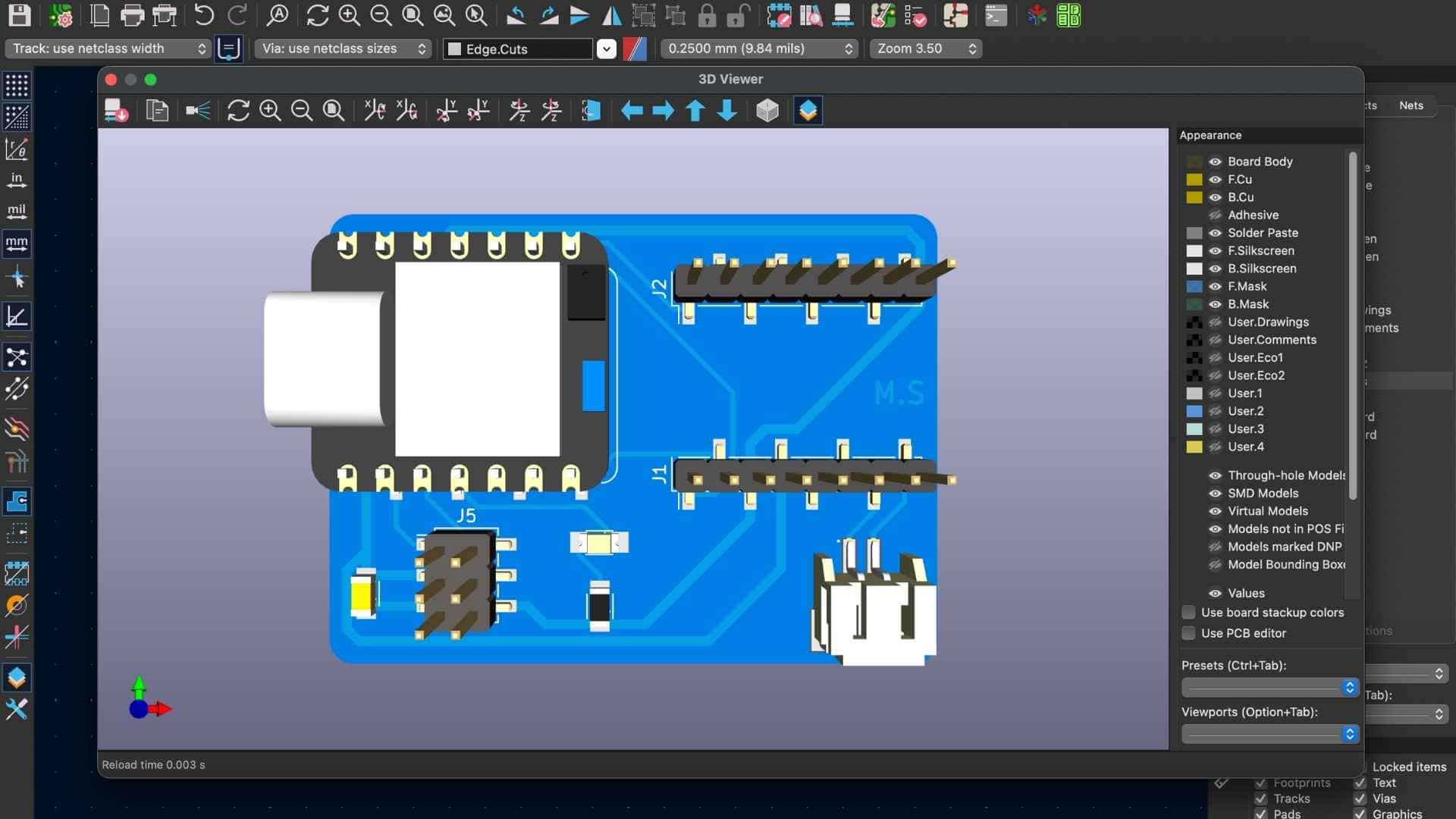
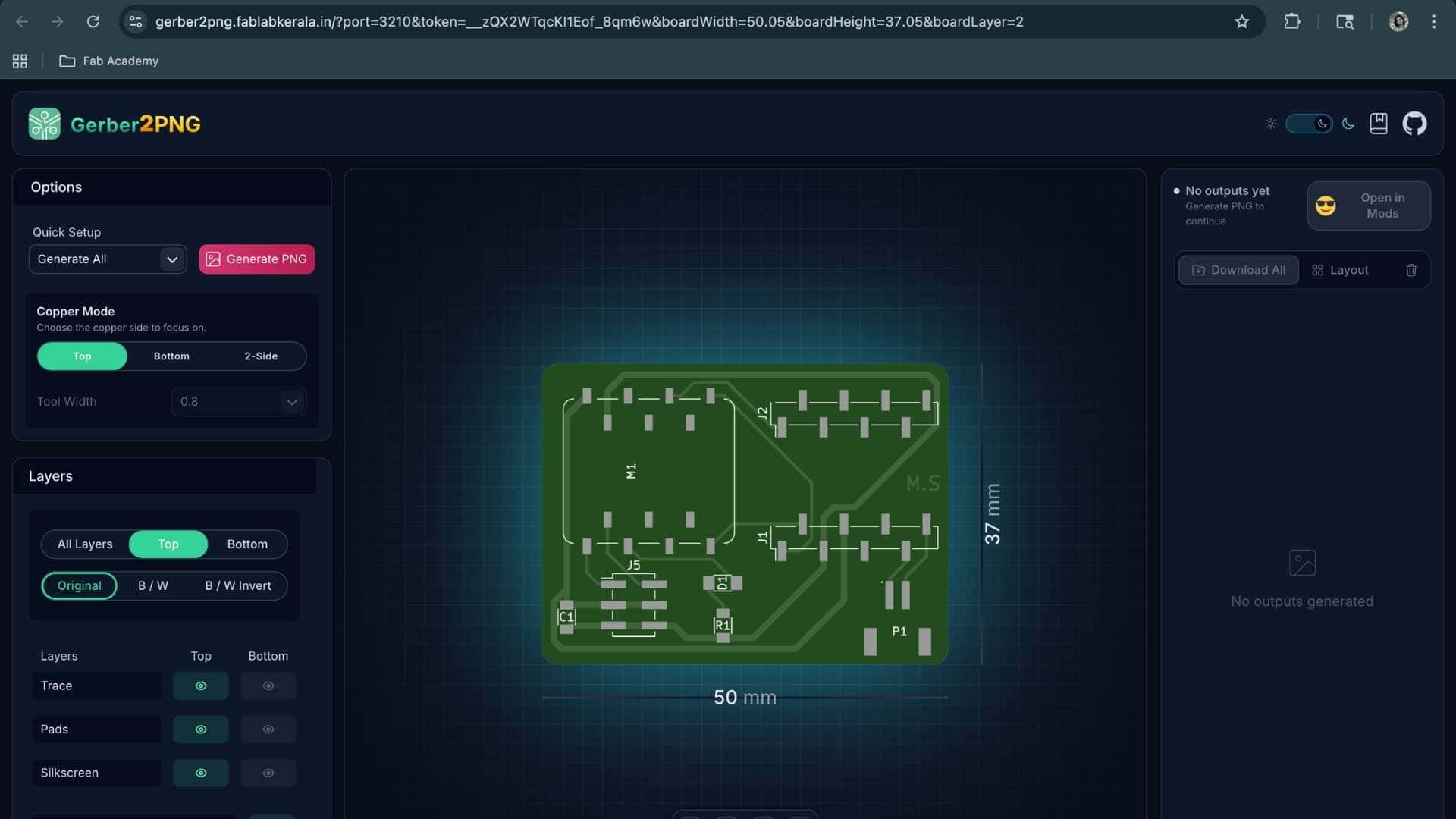
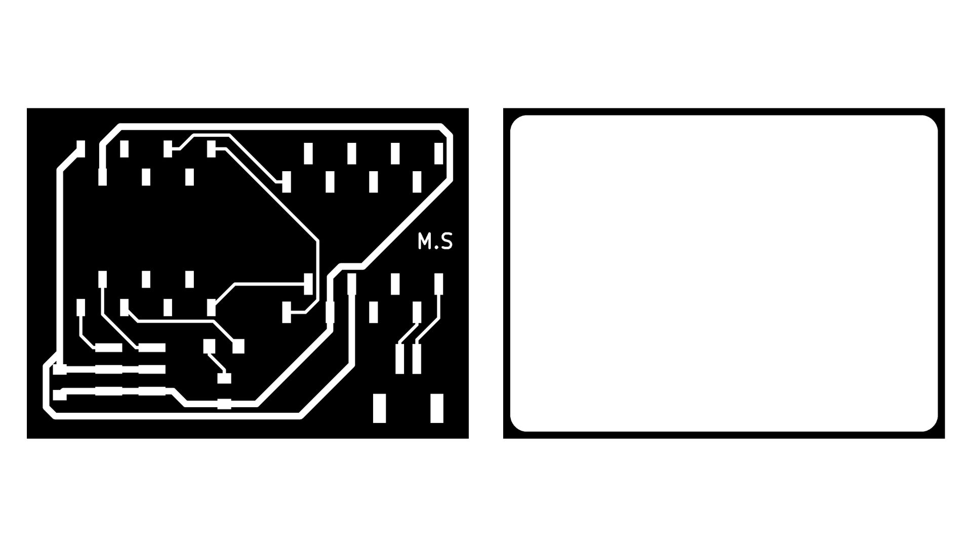
PCB Design
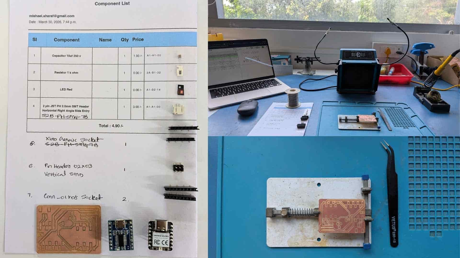
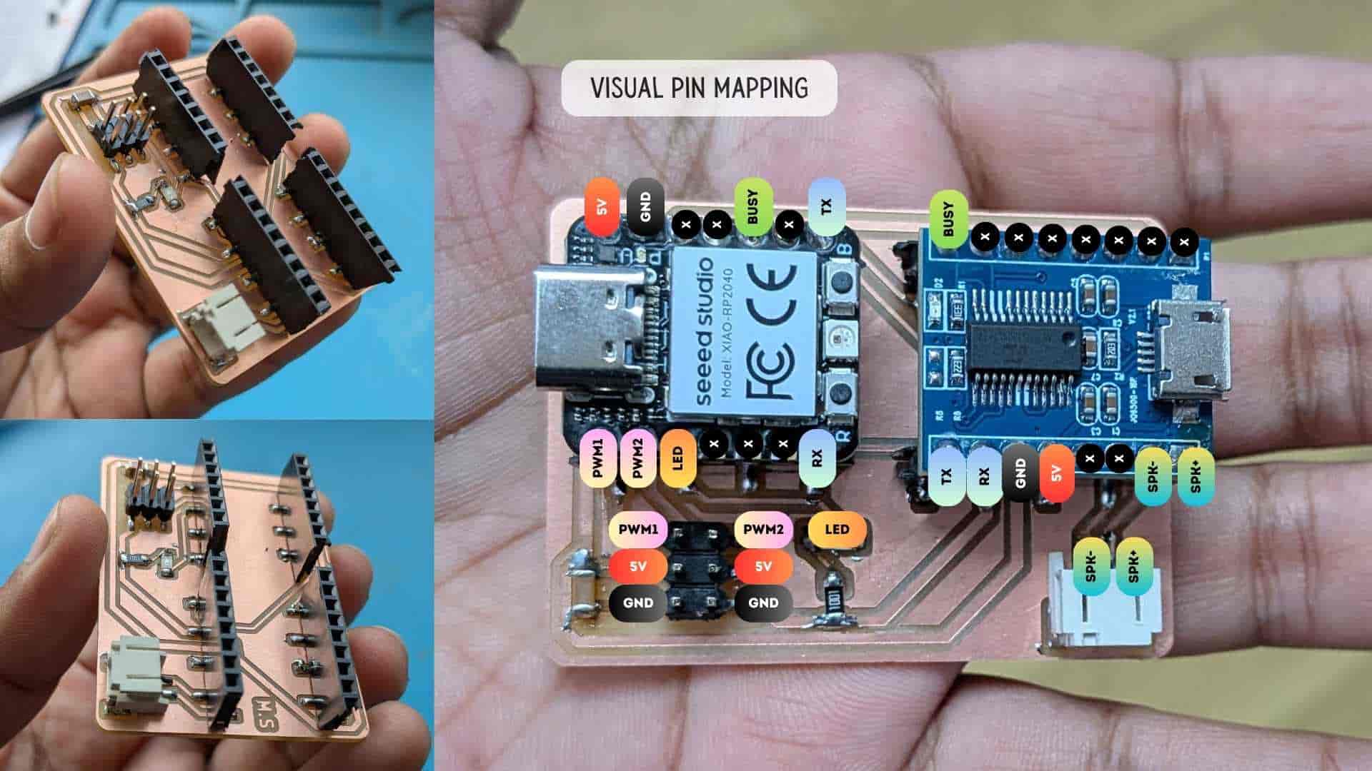
This week I designed a single-sided FR1 board to test two output devices together, a MG90S servo motor and a JQ6500 V2.1 MP3 module with an 8Ω 3W speaker. The idea was to have one board where the XIAO RP2040 plugs in via female headers and controls both devices independently.
Components
| Component | Purpose |
|---|---|
| XIAO RP2040 | Microcontroller - plugs in via female headers |
| JQ6500 V2.1 | MP3 player module - plugs in via female headers |
| MG90S Servo | Mechanical output - controlled via PWM |
| 8Ω 3W Speaker | Audio output - driven directly by JQ6500 |
| 10µF Electrolytic Cap | Decoupling - stabilizes power rail during servo spikes |
Schematic Design
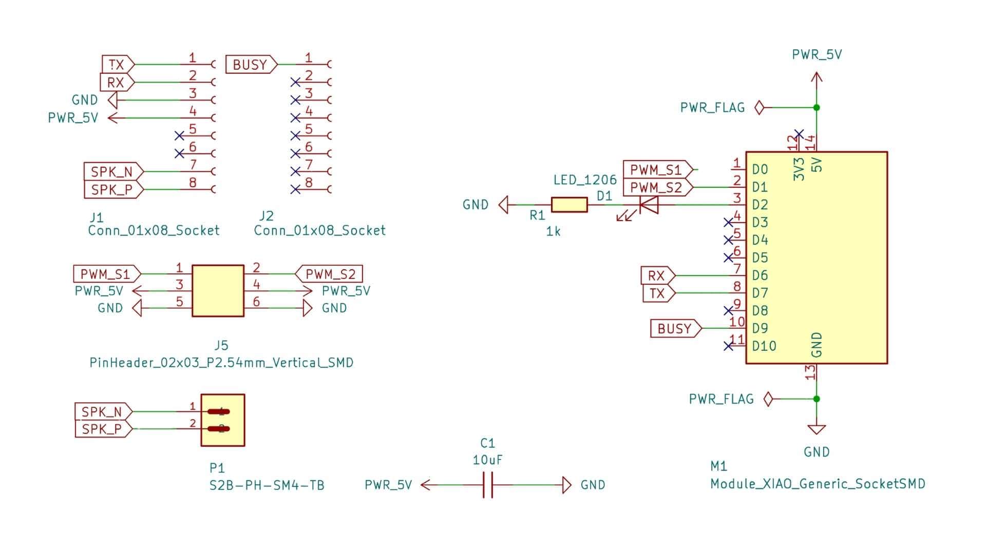
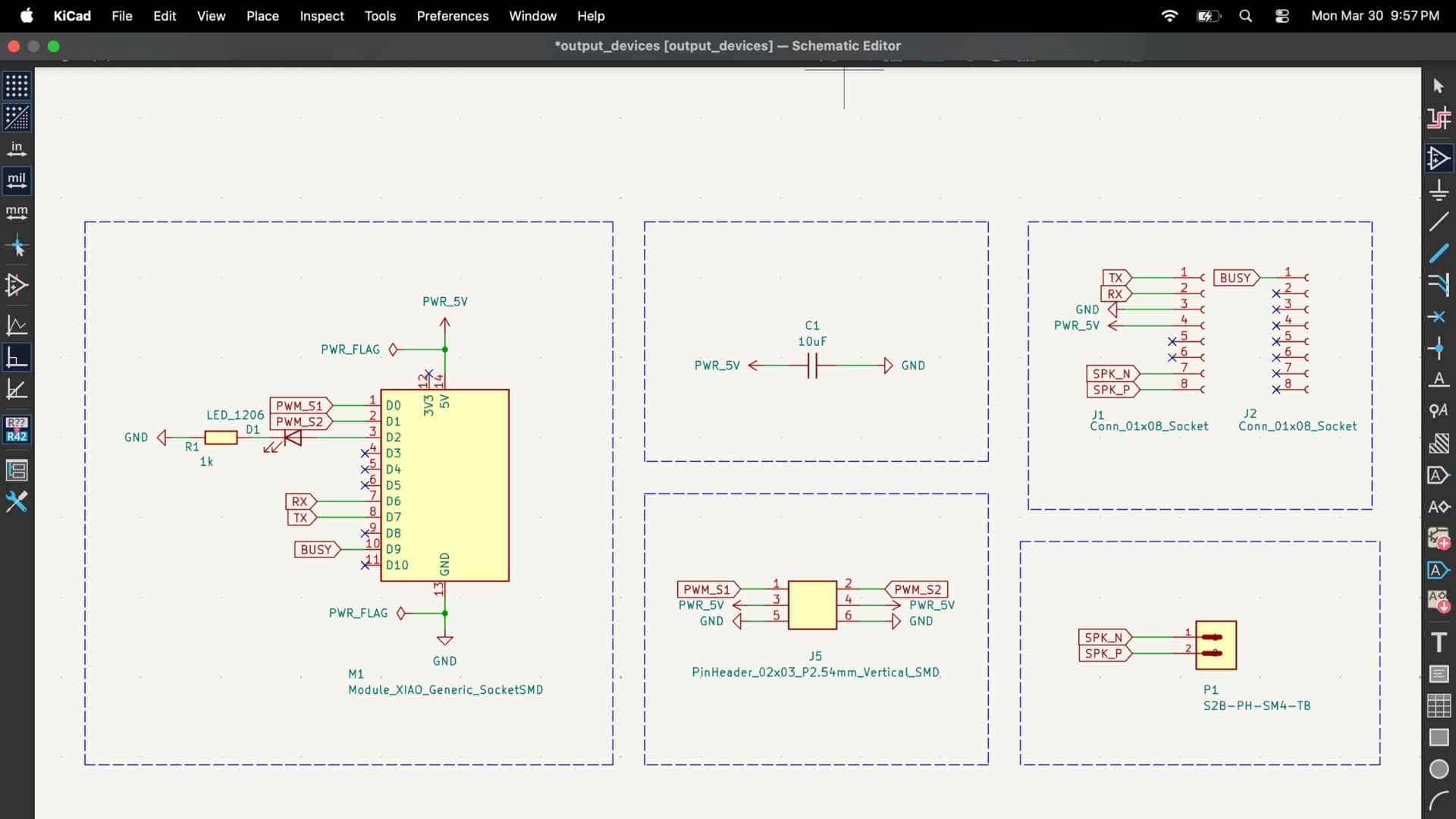
The key connections are:
Once the schematic passed ERC with zero errors I moved to PCB layout.
Board Setup
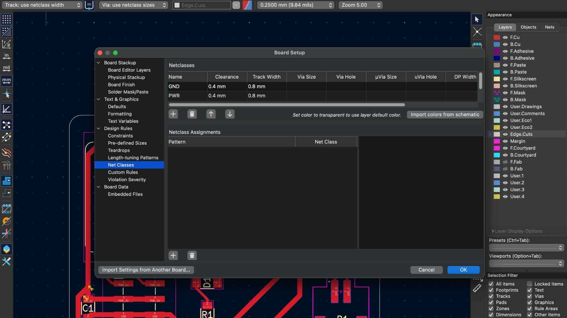
PCB Layout
| Rule | Value |
|---|---|
| Power trace width | 0.8mm |
| Signal trace width | 0.4mm |
| Clearance between traces | 0.4mm |
| Board outline tool | 0.8mm flat end mill |
| Trace isolation tool | 0.2mm V-bit |
Component placement logic:
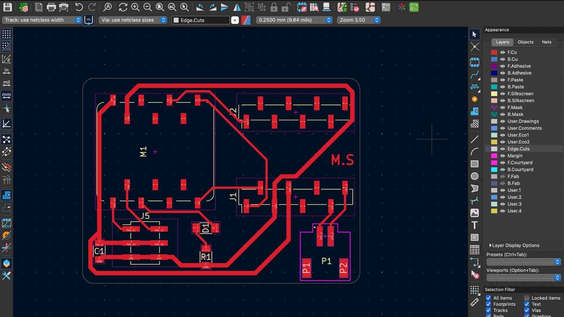
The DRC showed no errors at this point.
Initial Blink Test
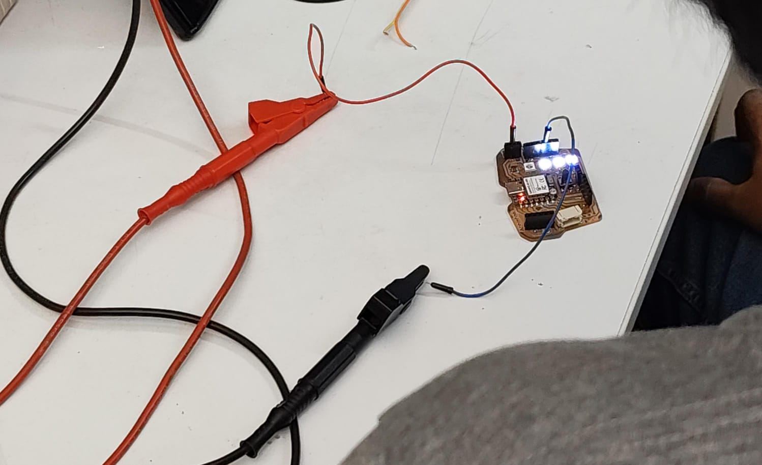
As a first step, I performed a simple blink test to verify that the board was working correctly. A basic program was uploaded to toggle an LED at regular intervals. The successful blinking confirmed that the board was powered, the microcontroller was responsive, and the programming workflow was functioning as expected. This gave me confidence to proceed with further development.
Code:
#define LED_BUILTIN D2
// the setup function runs once when you press reset or power the board
void setup() {
  // initialize digital pin LED_BUILTIN as an output.
  pinMode(LED_BUILTIN, OUTPUT);
}

// the loop function runs over and over again forever
void loop() {
  digitalWrite(LED_BUILTIN, HIGH);  // change state of the LED by setting the pin to the HIGH voltage level
  delay(500);                      // wait for a second
  digitalWrite(LED_BUILTIN, LOW);   // change state of the LED by setting the pin to the LOW voltage level
  delay(100);                      // wait for a second
}
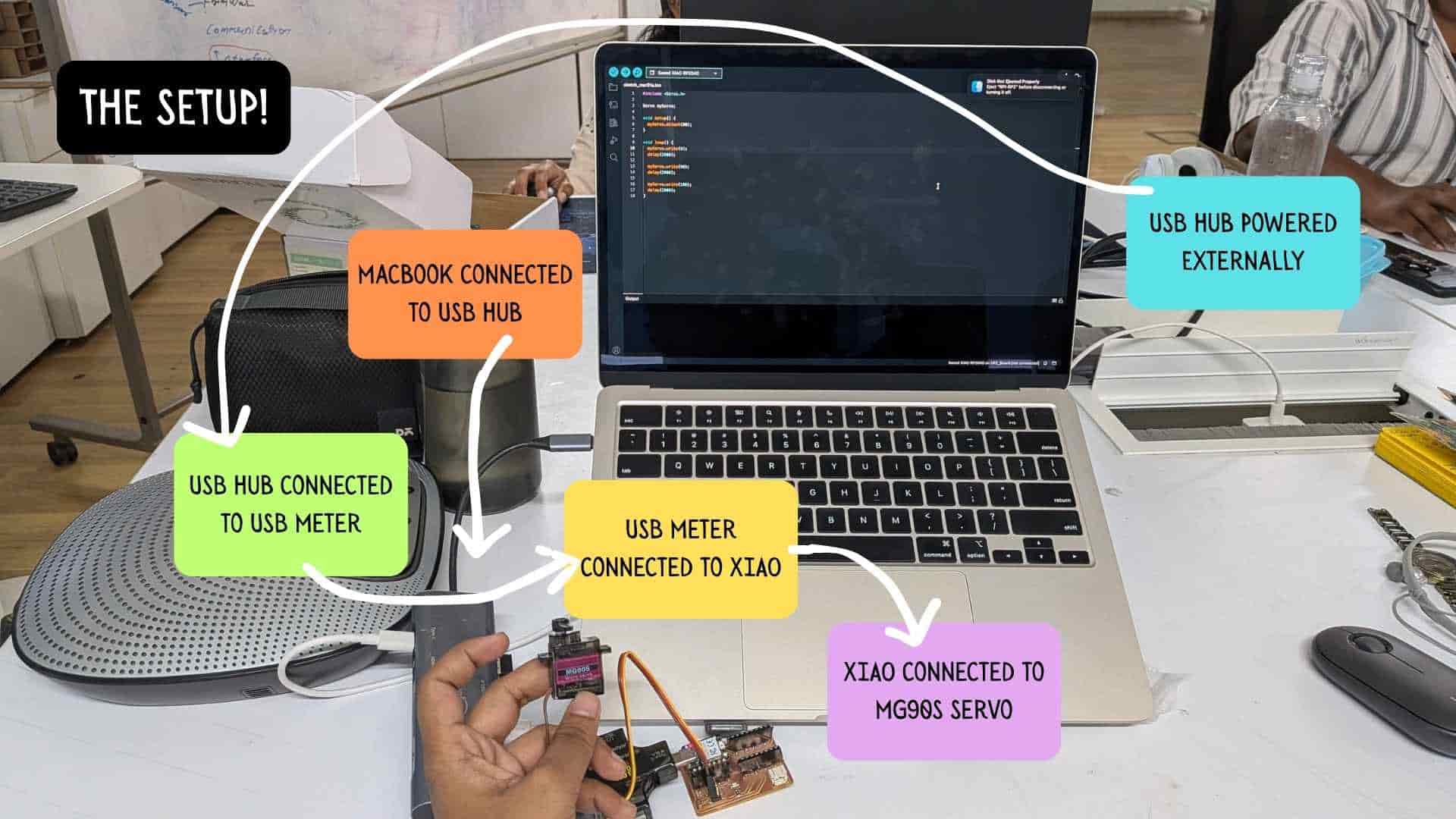
Testing Servo on Arduino IDE
Basic Test Code
#include <
Servo.h> Servo myServo; void setup() { myServo.attach(D0); } void loop() { myServo.write(0); delay(2000); myServo.write(90); delay(2000); myServo.write(180); delay(2000); }
It did NOT work, but WHY?
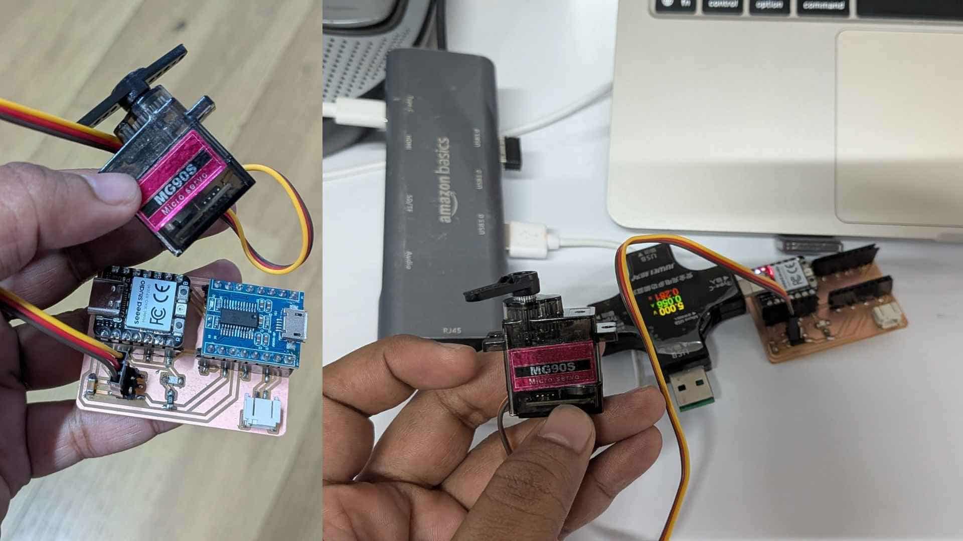
The Updated Setup!
MP3 Module Integration (JQ6500 + XIAO RP2040)
What I Set Out to Do
I wanted to add audio feedback to my project using the JQ6500 MP3 module, controlled by the XIAO RP2040. The idea was simple: trigger sounds based on input.
Setup

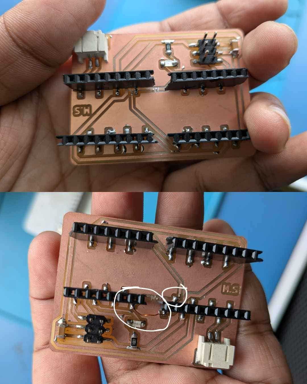
An initial misrouting of the RX and TX lines was identified during testing. This issue was resolved through PCB rework by introducing a copper jumper wire to resolder and reroute the affected traces. Following this correction, proper communication was successfully established.
Uploading Tracks to JQ6500 MP3 Module
To upload audio tracks to the JQ6500 MP3 module (V2.1), I followed a tutorial from Simple & Easy to Use MP3 Voice Module | JQ6500 tutorial and supplemented it with documentation from JQ6500 MP3 module guide (gogo.co.nz).
The MP3 files used for testing and mapping inputs were downloaded from Pixabay Sound Effects. Specifically, I sourced the “hello” and other relevant audio clips from: pixabay.com . These files were uploaded to the JQ6500 module and used in the serial input-controlled playback system.
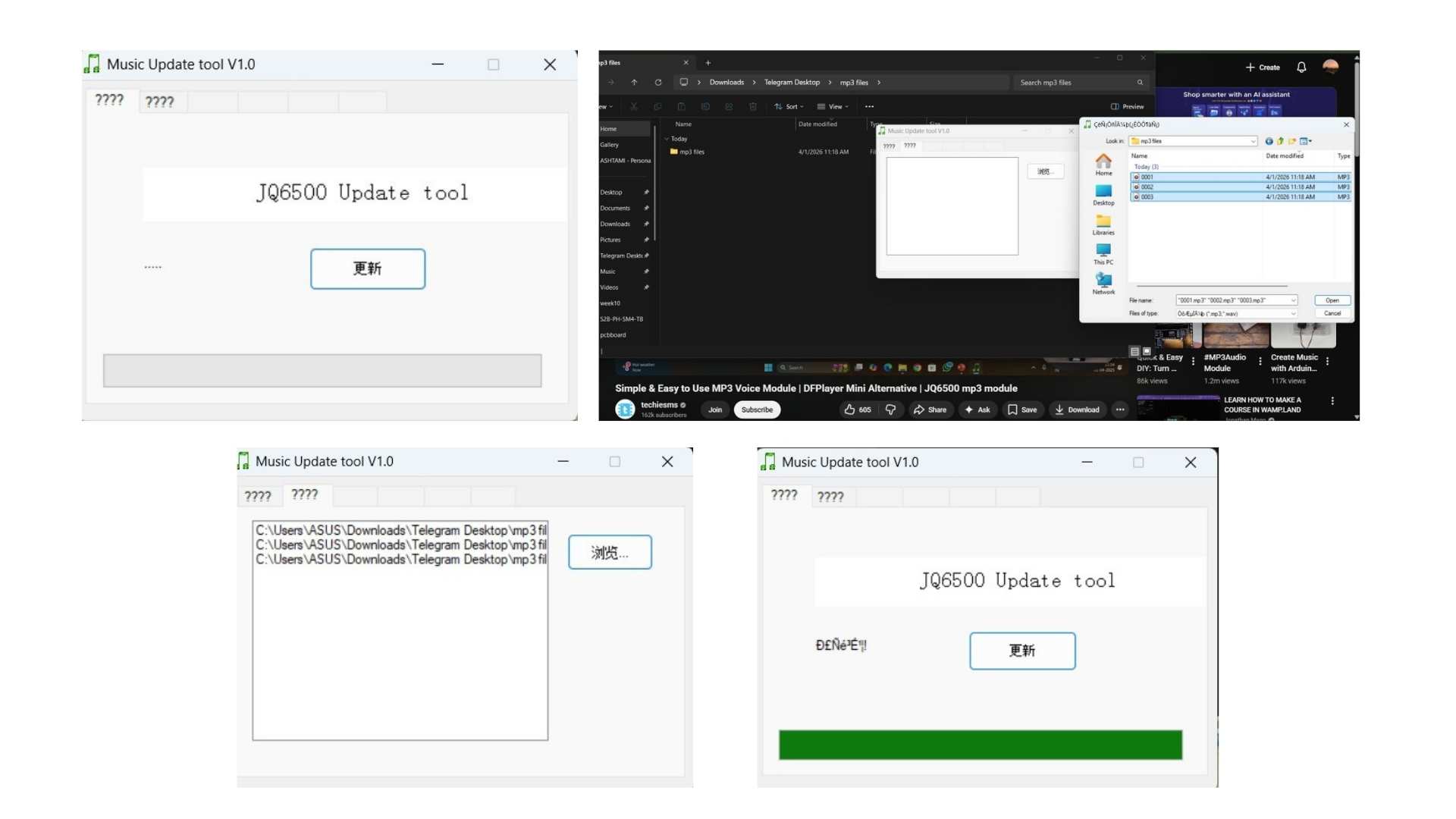
The upload process is supported only on Windows, so I used Ashtami’s laptop to transfer the files. The module connects to the computer via a Micro-USB interface, and files are uploaded using the dedicated Music Update Tool provided for the device.
File Requirements
Storage Details
MP3 Module (JQ6500) Testing
After resolving an initial hardware issue, I proceeded to test the JQ6500 MP3 module for audio playback. Based on a YouTube tutorial I referred to earlier, I downloaded a supporting library for the module and used the example code provided in the Arduino IDE as a starting point.
To adapt the code for my setup, I used ChatGPT to modify it for compatibility with the XIAO RP2040 and the JQ6500 module. The prompt I used was:
“Modify this JQ6500 example code to work with Seeed XIAO RP2040 using serial communication and play the audio tracks stored on the module.”
But, it didn't work.
What Went Wrong (and How I Fixed It)
mp3.reset();
mp3.setSource(MP3_SRC_BUILTIN);
mp3.setVolume(30);
Without this, it just doesn't respond.
Understanding File Selection
playFileByIndexNumber(n);
Testing Approach
With the help of ChatGPT, I arrived at a simple serial control system to isolate the problem and test the module’s playback functionality directly. The prompt I used was:
“Help me write a simple Arduino code to control JQ6500 MP3 module via serial input,

so I can play a specific track by entering its index number.”
The solution I implemented was:
int track = Serial.parseInt();
mp3.playFileByIndexNumber(track);
This approach allowed me to test audio playback by sending track numbers directly through the serial monitor, without worrying about the rest of the input logic.
Code to to play 0003.mp3 (single file)
#include <
Arduino.h> #include <JQ6500_Serial.h> #define mp3Serial Serial1 JQ6500_Serial mp3(mp3Serial); void setup() { mp3Serial.begin(9600); delay(3000); // allow module to boot mp3.reset(); delay(1000); mp3.setSource(MP3_SRC_BUILTIN); delay(500); mp3.setVolume(25); delay(500); mp3.playFileByIndexNumber(3); // plays 0003.mp3 } void loop() { // nothing else }
Code to play files in order (1,2,3)
#include <
Arduino.h> #include <JQ6500_Serial.h> #define mp3Serial Serial1 JQ6500_Serial mp3(mp3Serial); void playTrack(uint8_t n) { mp3.playFileByIndexNumber(n); } void setup() { mp3Serial.begin(9600); delay(3000); mp3.reset(); delay(1000); mp3.setSource(MP3_SRC_BUILTIN); delay(500); mp3.setVolume(25); delay(500); } void loop() { playTrack(1); // 0001.mp3 delay(4000); playTrack(2); // 0002.mp3 delay(4000); playTrack(3); // 0003.mp3 delay(4000); }
Mapping Inputs to Audio Playback
At this stage, I knew I could play MP3 files through the code, so I asked ChatGPT to help me create a version where specific serial inputs would trigger the corresponding audio files for my final project. The prompt I used was:
“Write Arduino code for XIAO RP2040 with JQ6500 MP3 module so that specific serial inputs play different audio tracks:

'h' for hello, '1','2','5','10' for coin input, 'r' for goal progress sound, and 'e' for ending happy note.”
The code I received and implemented was:
#include <
Arduino.h> #include <JQ6500_Serial.h> #define mp3Serial Serial1 JQ6500_Serial mp3(mp3Serial); void setup() { Serial.begin(115200); // wait for Serial (RP2040) unsigned long t = millis(); while (!Serial && millis() - t < 5000); Serial.println("Ready. Enter command:"); mp3Serial.begin(9600); delay(3000); // JQ6500 boot time mp3.reset(); delay(1000); mp3.setSource(MP3_SRC_BUILTIN); delay(500); mp3.setVolume(30); // MAX volume delay(200); } void loop() { if (Serial.available()) { String input = Serial.readStringUntil('\n'); input.trim(); if (input == "e") { Serial.println("Playing 0001.mp3"); mp3.playFileByIndexNumber(1); } else if (input == "1" || input == "2" || input == "5" || input == "10") { Serial.println("Playing 0002.mp3"); mp3.playFileByIndexNumber(2); } else if (input == "h") { Serial.println("Playing 0003.mp3"); mp3.playFileByIndexNumber(3); } else if (input == "r") { Serial.println("Playing 0004.mp3"); mp3.playFileByIndexNumber(4); } else { Serial.println("Invalid input"); } } }
With this setup:
This approach allowed me to map project interactions to audio feedback, making it easier to test and refine the interactive experience.
What I Learned
How This Fits the Final Project
Audio becomes part of the feedback loop-sounds mapped to correct/incorrect actions, rewards, cues. It adds a layer of anticipation and response that visual feedback alone doesn't provide.