system integration
Assignment
- Design and document the system integration for your final project
Added Unexpected Bonus
Downloaded and Used KRITA:
I wanted to be able to use pictures and make a diagram using this pencil tool taht I got. CoPilot suggetsed I use Krita. I double checked with claude since claude knows what I already have. Claude confirmed Krita was a great choice. It seems easier to use at first go than GIMP. I probably should have done a tutorial. It's on the list for after Fab.. on the when time list. I'd love to say that I learned to use I, but I really just limped along usinga ton of layers. That said, my wiring diagram below is done with Krita.
The Individual Work
My asset files are here.
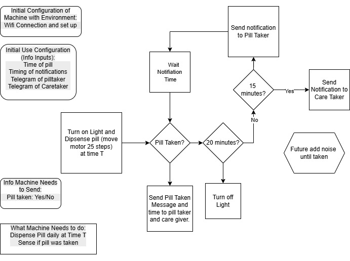
System Flow
I made a flow chart of how the programming weaves into the physical dispenser.
Regulator Lessons
Then we moved to plugging things in.. which is a bit scary for me. I don't have much experience or training with electrity and wiring. So when it comes to plugging anything up.. I really want to have guidance.
In open time, the instructors were helpful with resources for understanding regulators.
This resource provided by Ricardo Marques explains about noise suggesting that a capacitor is put between the voltage source and the regulator.
The voltage regulator works best and will be most efficient when a clean DC signal is fed into it. We don't want any ac noise (ripple) imposed on the DC line voltage. The capacitor, in essence, acts as a bypass capacitor. It shorts the AC signal of the voltage signal (which is noise on the voltage signal) to ground and only the DC portion of the signal goes into the regulator.
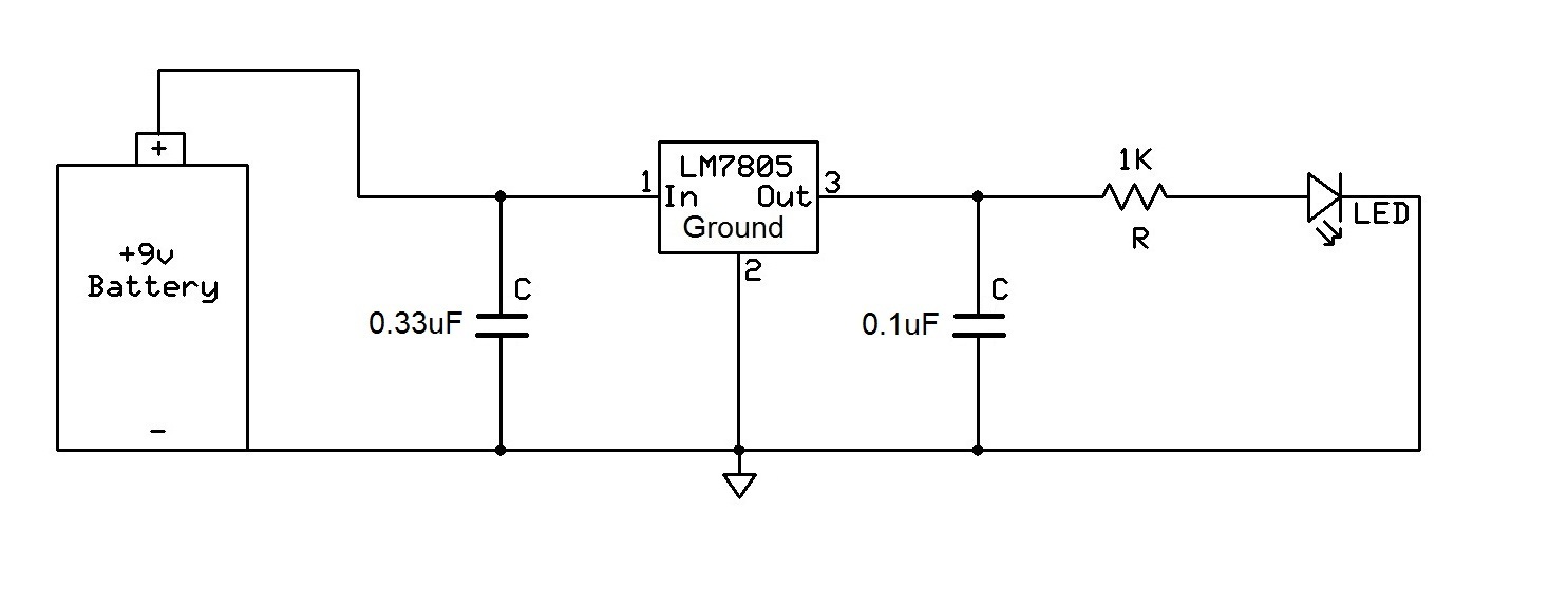
Ricardo Marques provided this graphic from teh resource, which suggests a second capacitor after the regulator.
The second capacitor, the 0.1uF ceramic capacitor, is hooked up after the voltage regulator. This capacitor is there again to filter out any noise or high-frequency (ac) signals that may be on the DC voltage line. ...in other applications, such as when outputting voltage to power a logic chip, which needs a precise voltage fed into it in order to give the correct logic output, it is crucial.
I am wondering if my modules already have some of these capacitors on them.
I was really aiming to understand the physical wiring... show me point A to Point B.. where are these wires connecting? Does it matter if they branch out in a Y before, or meet at the edge of the regulator? Is there best practice.
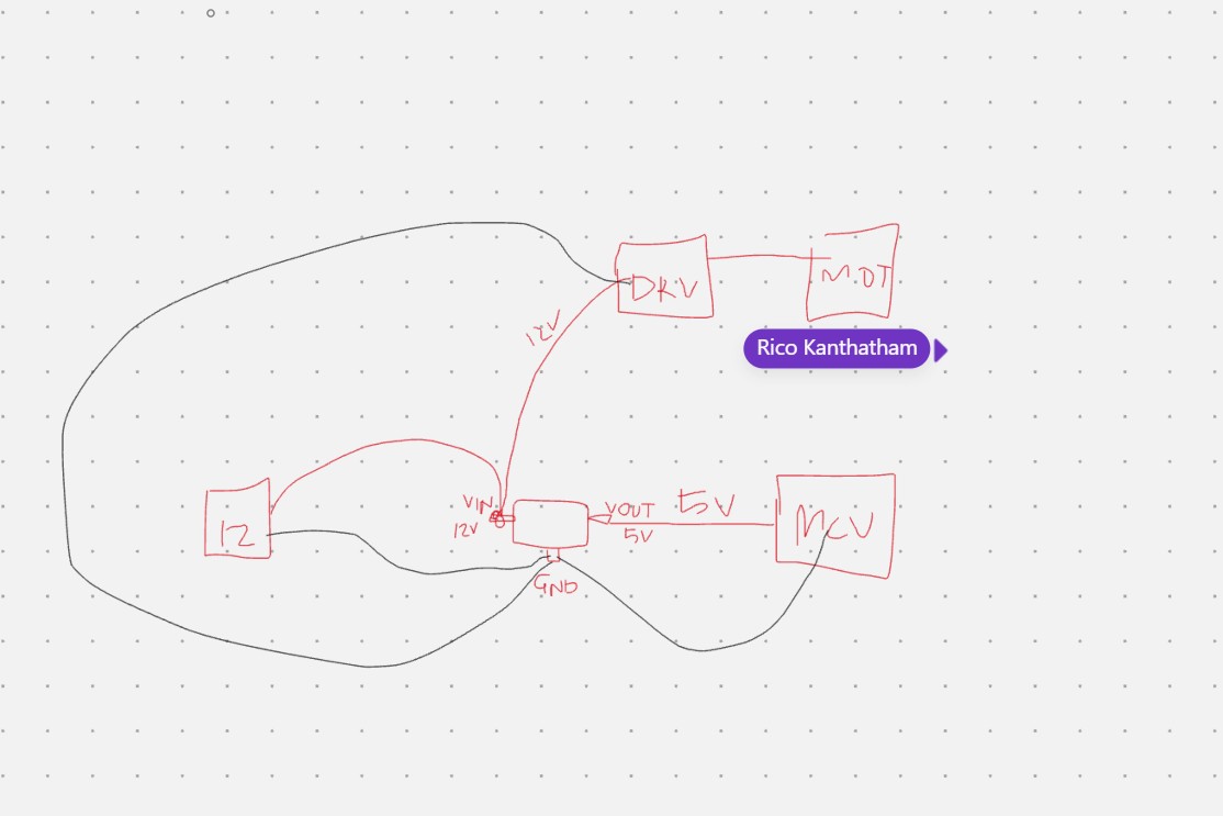
Rico Kanthatham offer the picture below to help with some wiring and practical knowledge.
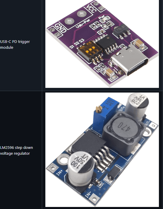
Miriam - AKA Ye Eun Miriam Choi shared these two regulators. I was happy to see some more examples of regulator modules.
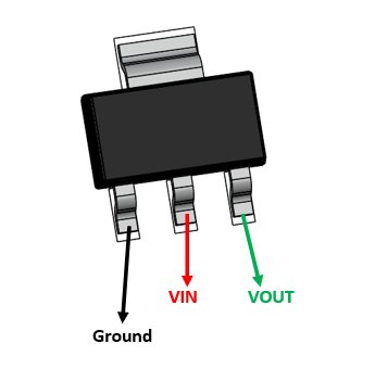
Adrián Torres provided a picture of a simple surface mount regulator - maybe like the ones he uses on his boards.
I need to do more research to understand, when we use the small SMD adn when to use the module. Since I am a chicken newbie.. I am going to stick with the modules for now since they seem to have the capicitors and other things to make the regulator safe adn work efficiently.
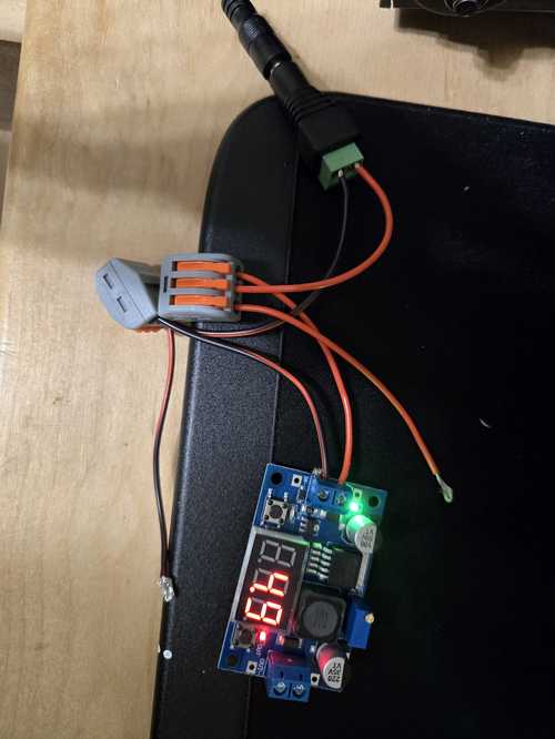
When I got back to the lab, Mr. Dubick aka Tom ordered me a regulator with a big screen on it and potentiometer for adjusting voltage, and some connection clips that allowed me to experiment with the regulators and get comfortable with wiring.
I found the data sheets.
DataSheets: - LM 2596 - big one with screen - MP1584 - small 5V only, no potentiometer
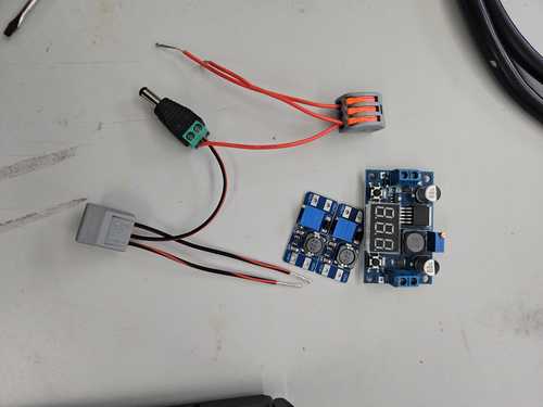
I wired up a regulator using the 12V that I had and the splitters that Tom provided. We discussed making a board with traces for the final use, but using these clips and mocking up the voltages that I was trying to get. He gave me both a voltage amplifier and a I had bought some smaller voltage regulators from Amazon.
I pluged these in and adjusted the voltage down to ~5V using a small screw on the corner of the blue potentiometer. At first, I thought it was broken, but I found a resource (or I may have asked claude - I cant remember _ if I just googled my issue or used my Claude app) that mentioned that sometimes you have to really turn it , maybe even 10-15 times, before the potentiometer will kick in on the first run. It was much less sensitive than the potentiometers that I am used to with the motor drivers.
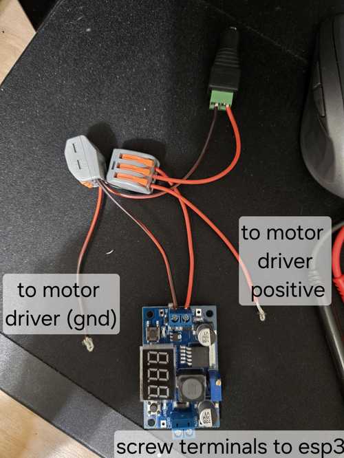
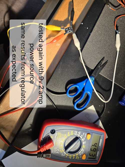
After getting comfortable with the adjustable big screen regulator, I changed to the small 5V output only regulator that I am planning to use in my project.
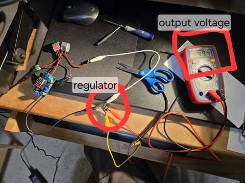
Then I hooked up the 2 Amp 9V power supply and confirmed that it didnt matter what the power supply was. As long as it was in range, then it would put out the voltage as adjusted.
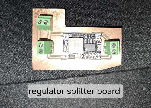
After working with the regulator claude and I designed a layout for a splitter regulator board.
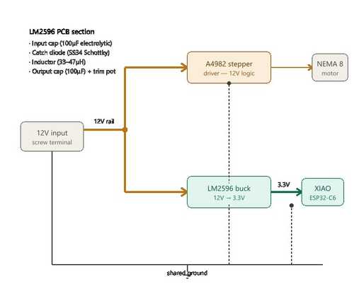
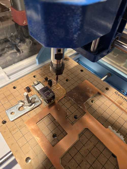
Then I designed it in KiCAD and printed it on the Genmitsu using easytrace5000. It was the first time I had ever done drill holes on the Genmitsu. I am proud to say that I am getting faster and more confident about milling PCB boards on the Genmitsu at home and the carvera at school, just need to do it a few times successfully to cement the process into the brain.
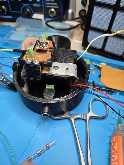
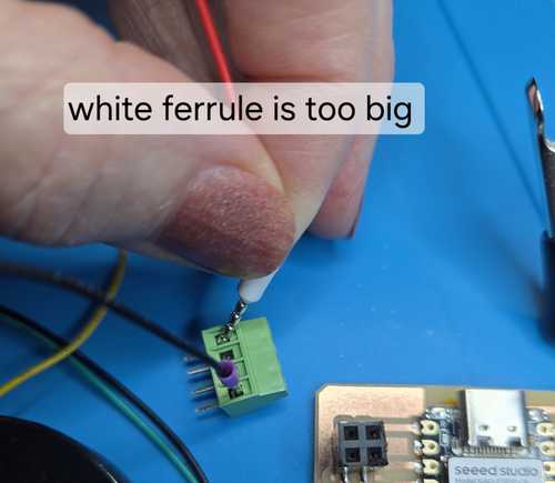
In order to make this board, I had to import footprints and create my own footprints in KiCAD. I started using terminal blocks for strain relief and crimped wires with ferrules. However, in the end, the ferrules that I had purchases were too big for the terminal blocks. The lab is ordering some new ones that I will try next week. My motor wires are very small, so we are going to try 26 AWG ferrules. 22 was the smallest in the kit I have.
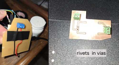
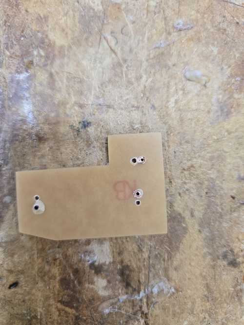
I had to decide how I was going to mount the terminal blocks. If they were on the top - how would I solder them? On my original board, i put the terminal block on teh backside of the board so the prongs came through the board and I could solder them to the copper on the top. On these boards, because of how I want to mount them, I need to be able to solder on the back. So I made vias and put rivets in them.
I learned to use the Rivet Punch and place the rivets into the board and then line up the punch with the correct die to flatten the rivet to the board. The wrong die was originally in the punch so it pushed the rivet to one side instead of flattening it.
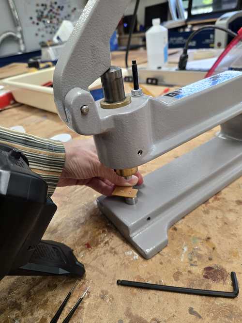
On the back side, the board cracked a bit after punching the rivet, but it was functionally fine.Wh oknew I was so strong?
After getting all the rivets in, I am able to put my regulator splitter board together. I plan to mount this on the underside of the board holder then connect it to the power jack.
The 1.0 rivets do not work well with the terminal blocks we got. They are too big for the small legs and do not create a good connection. It's crazy. Soldering to the rivet on the back side was super hard on a couple of them. I think we had flux from teh board maybe that was melting and making it difficult to get a connection to the rivet. Even Collin checked it and couldn’t believe it. I did notice the stubs of the terminal block were loose in the holes. I am thinking about sticking a piece of wire in with the terminal legs to create a firm connection to the wall of the rivet and packing it with some solder paste in there as well, but i want to be careful that the flux in the solder paste doesnt get stuck in teh hole making it even harder to get a connection. I may just end up threading the wire directly into the hole and to the board. The mounting itself will create enough protection to make sure the wires are not pulled from the board.
More resources on the DRV8825
I thought I was burning through motor drivers.. and maybe I was.. or maybe I have bad eyesight and I was using a cheap screw driver that came with one pack of the motor drivers. I put on a new one.. changed to a high quality screw driver that I could see what seated into the potentiometer, and now readings are changing. I was able to set my potentiometer up a bit higher closer to 0.3 and then it was able to move the center pill divider and move forward.
In open time, they provided me with more resources for the DRV8825. Here is a link to those resources.
Other Stepper Motors I could use
Another stepper motor that I could have used as suggested in open time was the hobby motor 28BYJ-48. I have played with this one before with the arduino. Here are some resources for that motor. However, on further research, the torque on these motors is the same as my Nema8. I am going to stick with my nema8 and learn how to maximize the torque that I get from it.
Wiring
I decided that I wanted to lay everything out and make a clear wiring diagram so that I could figure out what kind of wire management I needed and how I would be mounting my board into my physical system. I looked for an open source program that was easy to work in with JPG files. I found Krita.
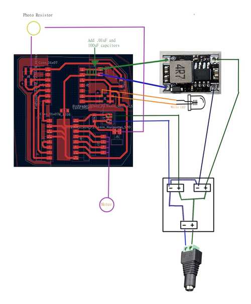
I used this diagram to lay out everything I would need to fit inside the body of the machine so I could work on how I would route all the wires. I did some modifications to the CAD model of the body to route the LED wires. I used these wire guides and integrated them into my pill body.
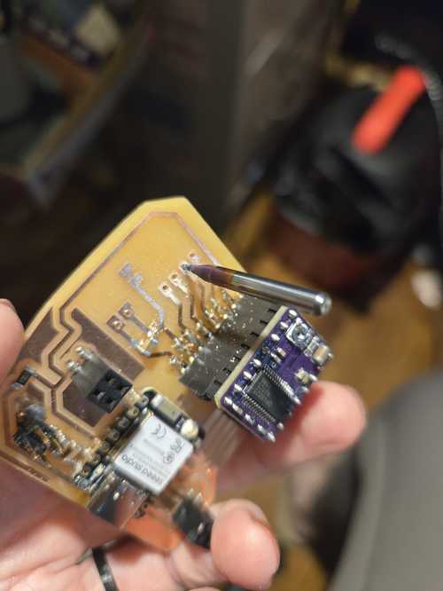
Then started to model how I would mount the board. My original board would fit, but I hadn't considered how I was going to mount it, so I milled a new improved smaller board.
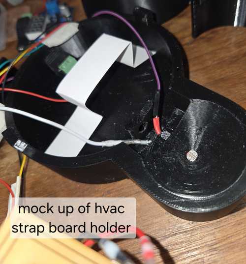
Then for mounting, I decided to use a springing tension mount using a metal strap. My walls are tapered slightly, so this will help hold the strap in place, but make it easy to take in and out as I figure out the exacts of how everything works together.
I am waiting for 3 straps to come back from the office to make the actual strap, but I mocked it up with paper board. The idea is that the big board sits on top with its terminal facing down to the power board with is mounted with spacers off the bottom. I am hoping to use one screw through both boards, but we will see. If not I will use spacers on both sides, to be able to attach both boards to the strap.
Then I started working on how the wires would route inside the body of the machine. I added wiring routing bumps to route the wires from the light down to the board and stabilize the light on the body in the machine.
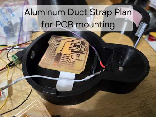
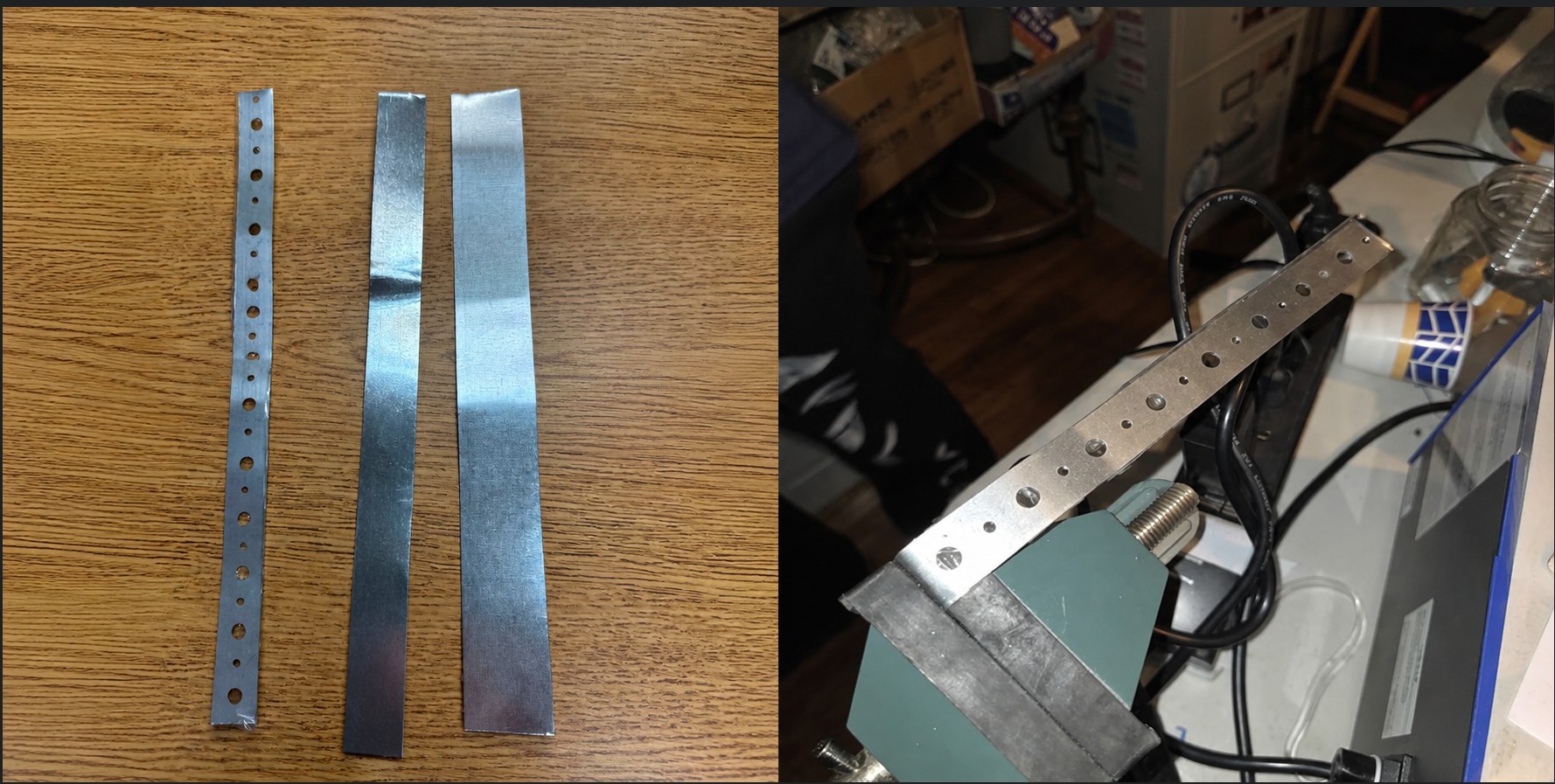
Straps
They brought me three straps from the shop and I decided to work with the thinnest and lightest and see if I need something more firl later. I used a vice to bend it, but later found that it was easier to use needle nose pliers.
Board Holder
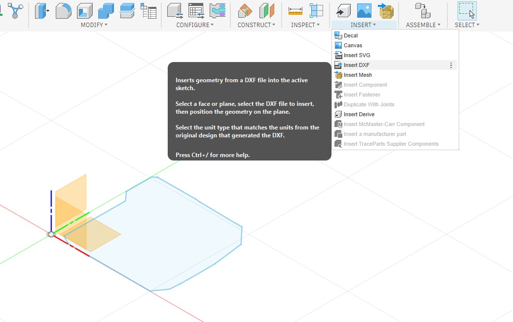
I went to export my board edge as a DXF from Kicad and it really gave me issues. It wouldn't import to Fusion 360, and it wouldn't open in inkscape either, but i could open it in notepad and see that it was there, or something was there. So then, I plotted as an SVG and started working with it there. When I opened it in anything, I could not see it. The boarder is white in kicad and I wondered if it was exporting it white on a white background. I opened it in inkscape and did a "select all" and sure enough it found something.. and then I changed the stroke to black and presto it showed up. I then saved it as a DXF and was able to import it into Fusion 360 in the correct orientation and scale.
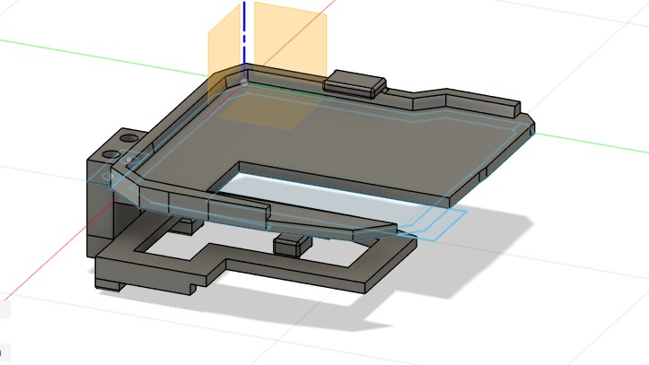
After I designed board holders for the pill board and the power board, I designed a spacer for between the board that had a slot to fit on the metal brace. The spacer will allow me to mount the terminals on either side of the power board depending on what works and if i want to use them. It also gives me a bit more room to thread the wire to its ending location.
While I was fitting my brackets and board holders, I broke the female connectors for my motor driver off the board. Urgh.. here goes another hour to fix that. Bummer..
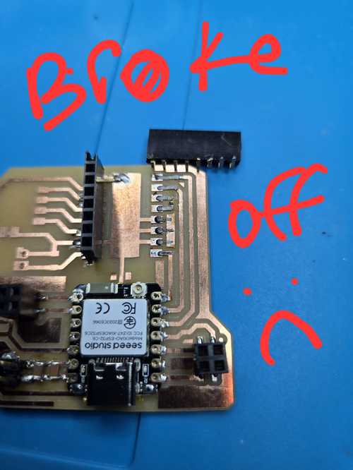
Fixed that and improved upon it with some hot glue to secure the connections once they were soldered and confirmed as good with the multimeter.
Ferrules Continued
Since my original Ferrules were too big, we ordered smaller ones that worked well. I still need to do some experimenting with the via sizes and the terminal blocks to trouble shoot connections, but the new ferrules are a good fit.
I used the commands to manually drill holes in my PCB to use a new terminal block and smaller 28 AWG ferrules for better strain relief on my motor wires. I loaded a .9 bit and made 4 holes 2.54 mm apart.
| Command | What It Does |
|---|---|
M3 S10000 |
Turn on spindle at 10,000 RPM |
M5 |
Turn off spindle |
G0 Z2 |
Rapid move to 2mm above board surface (safe travel height) |
G1 Z-2.0 F40 |
Plunge through board at 40mm/min (controlled cut move) |
G91 |
Switch to incremental mode (each move is relative to current position) |
G90 |
Switch back to absolute mode (moves relative to zero point) |
G0 X2.54 |
Move 2.54mm in X direction (one pin pitch) — use in G91 incremental mode |
| Zero X / Zero Y | Set current XY position as 0,0 origin in Candle |
| Zero Z | Set current Z position as Z zero (board surface) |
G0 |
Rapid motion — moves as fast as machine allows, for positioning only, never cutting |
G1 |
Linear motion at controlled feed rate — always use for plunging into material |
F40 |
Feed rate of 40mm/min — stays active until changed |
Z2 |
2mm above Z zero (board surface) — safe clearance height |
Z-2.0 |
2mm below board surface — ensures clean breakthrough on 1.65mm board |
S10000 |
Spindle speed 10,000 RPM |
At the end, I did end up having to use the drill bit by hand to finish the cut through the board.
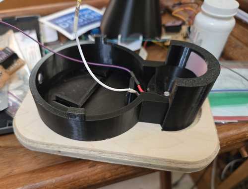
Base Plate CNC
To hold the pill catcher to the base, I CNC a wood plate with an impression for the machine and the catcher. This will also help me with my CNC confidence on the big machine at the lab.
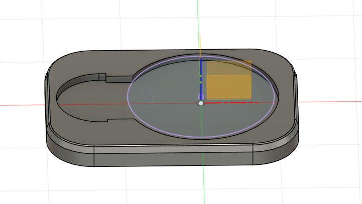
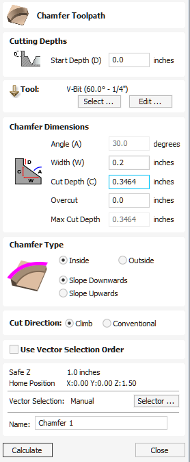
When I got to the lab, with help from Collin Kanofsky and Zack Budzichowski, we worked on making tool paths for a 3D cut, but then found that we would need to extend the part down and it was more complicated than it needed to be. I went back to the file and projected an outline and exported as a DXF. I used that dxf in the 2D mode and then used a chamfer path with a v bit to create the level all the way around.Vetric has a site that talks about the chamfer toolpath.
I used the sander afterwords to clean up the edges and then my base fit perfectly inside with a pressfit, and my pill catcher had some wiggle room so it could be used or not used depending on the pills being distributed.