Final Project
Summary
My asset files are here.
Pill Dispenser Introduction
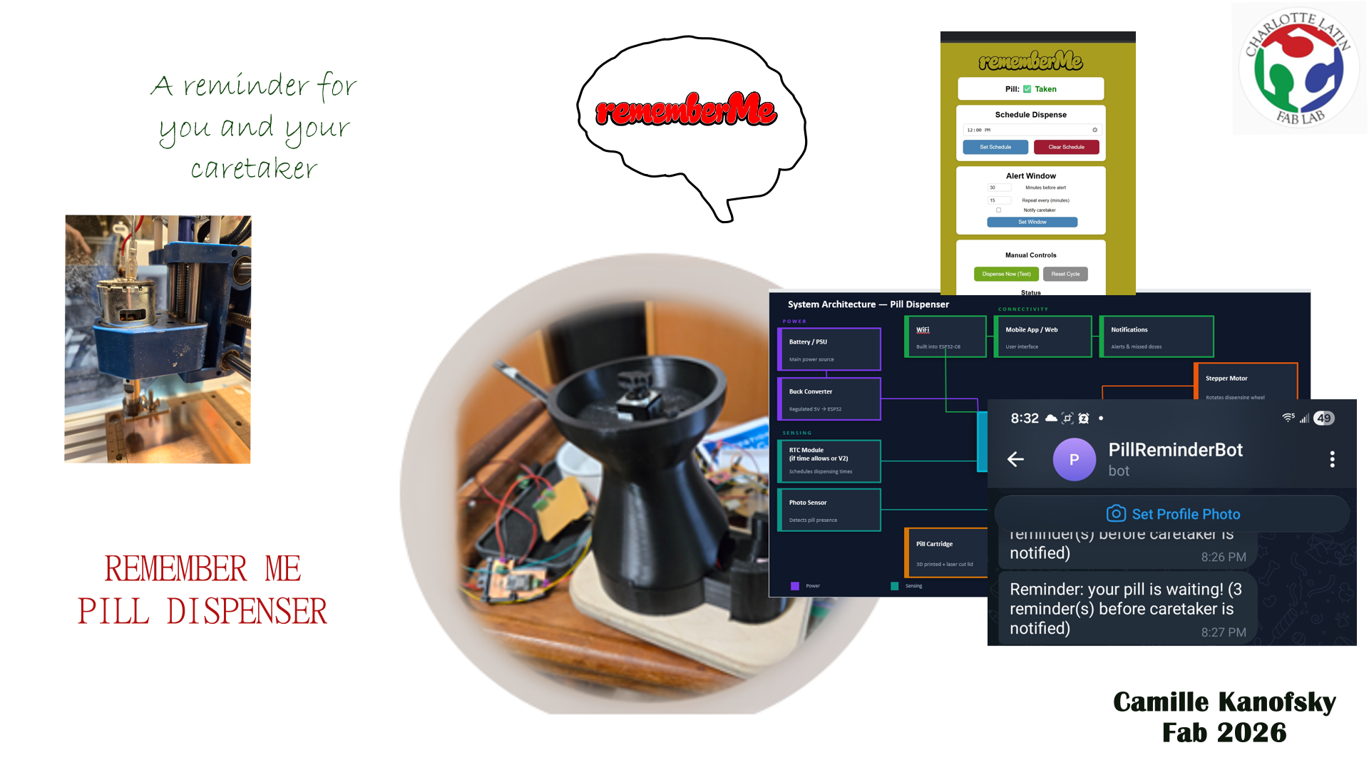
I would like to make a pill dispenser that would help my nephew take his medication for the day. Then send him a reminder before letting my sister in law know if my nephew has taken his medication for the day.
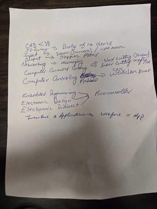
Breaking it down into sections: - pill dispenser body - pill cartridge - sensor or camera in dispensor area - app to notify - electronics to make it work
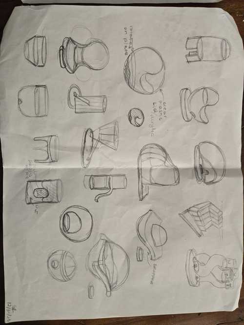
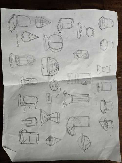
I worked with my daughter, Sage Kanofsky, to make sketchs of a pill dispenser. She is in Industial Design school at Georgia Institute of Technology. She is currently studying abroad the Polytechnic University of Valencia.
Past Pill Dispensers at Fab
[Griffin van Horne - Fab Academy 2021] (https://fabacademy.org/2021/labs/dassault/students/griffin-vanhorne/projects/final-project/) made a small handheld version with bluetooth.
Corey M. Rice : Fab Academy 2017 made one that distributes the right amount of a whole bottle of pills.
Lily Yeazell at MIT made the cutest pill box!!
Loes Fab 2021 made a box with alarms.
Miriam Choi showed this instructables project in her presentation. It is very similar in many ways to what I was thinking. They are using an arduino and an LCD. I am using an ESP32 and an app. My design is original and my version is upgraded with the purpose of caretaker notifications and interchangeable cartridges.
3D models
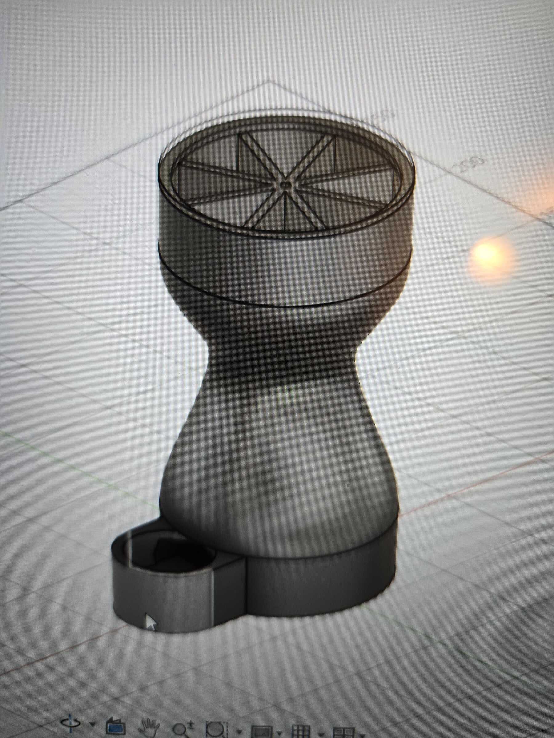
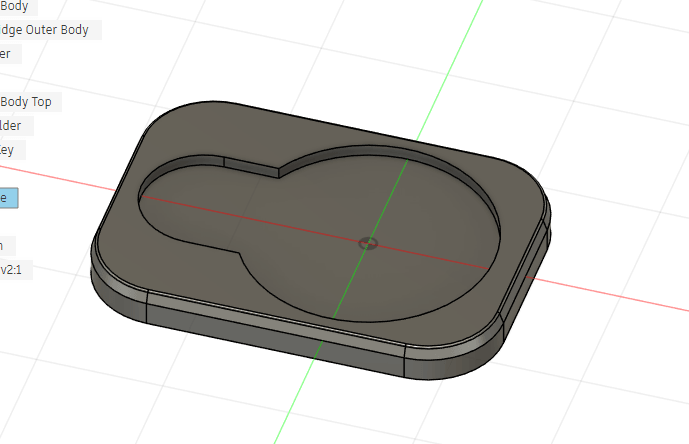
Then later I worked in Fusion 360 to make a 3D model
We've been discussing this dispenser and a few other items in what we call the "remember me" line. This would be helpful not only to Mika, but also to me and my family as I age. My father had alzhiemers and as he aged, t he more things that he had to help with memory, the more independent he could remain. I would like to create things that make the burden on family less, and increase the feeling of independence for all who struggle with memory for one reason or another.
I have seen that other pill dispensers have been done as fab projects. I hope that mine will be different in a couple of ways:
-
Cartidges that can be preloaded
-
Messages sent first to the pill taker, and second to the car giver
Timeline
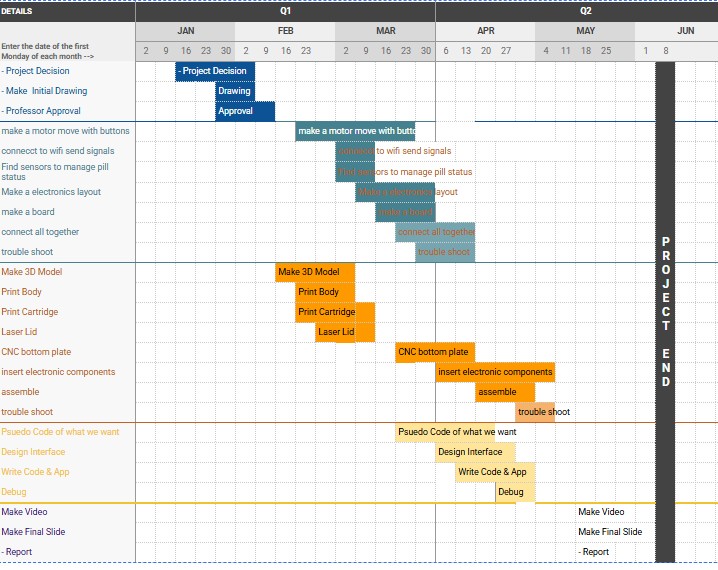
Then I also met with DR. Taylor who helped me related each part of my project even better to the weeks we will have in Fab.
3D Printing
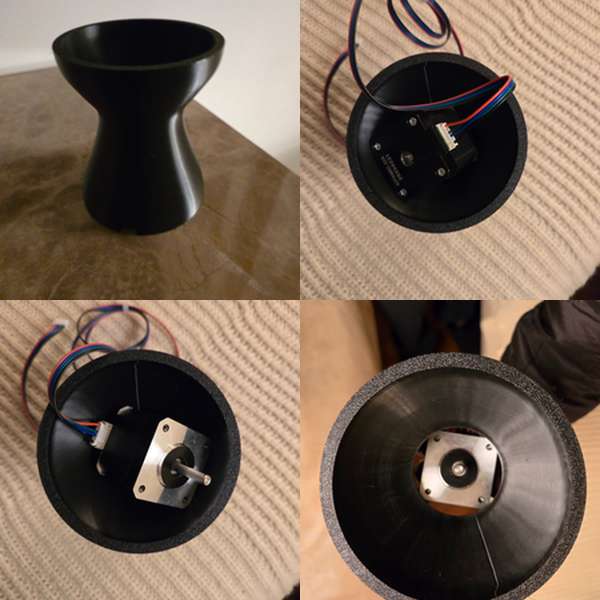
During the modeling week, I worked on my body parts and cannister. The body I printed was too small for the motors that we are using at the lab. I could ordeer a smaller motor, but I want to stick with what we know for now and get everything working, so I will change the model a bit to fit the NEMA 17.
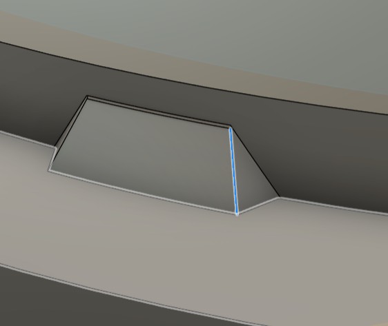
I made many notches and other additions to the CAD model to make the mechanics of the dispenser easier. Example: the stop for the acrylic piece at the top so that it doesn't spin past the edges when its closed.
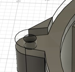
notch from teh body to the bottom body.
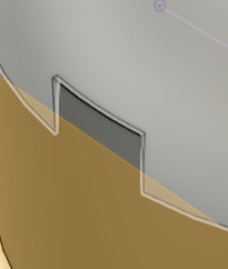
Notch for the catridge to seat on the top body
During the modeling week, I worked on my body parts and cannister. The body I printed was too small for the motors that I had. I asked for a NEMA 8 which is smaller and still has enough torque for my application.
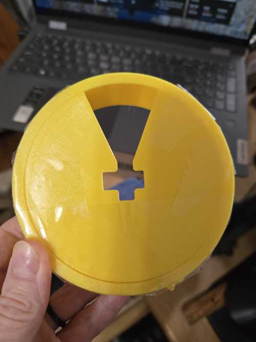
My first print of the cartride outer body, i had a few errors. I had combined the outer rim and the bottom to one stl to print, but didn't notice that i had made the bottom a slight be smaller in case i wanted it to spin in the original desdign. I also needed to cut the center in a cirlce so the key can spin freely inside the cartdidge and only turns the pill divider to push the pills.
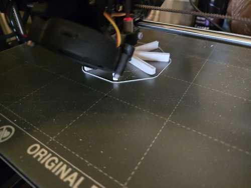
When printing the divider, the edges were coming up on my prusa MK3s. classmate Angela Horstman suggested that I add more of a brim to help it adhere better.
 I
I
I printed a new pill cartidge all as one piece with a cut out in the middle for the "key" to spin.
The tree supports on the latest body print are so cool. I had to take a pic.
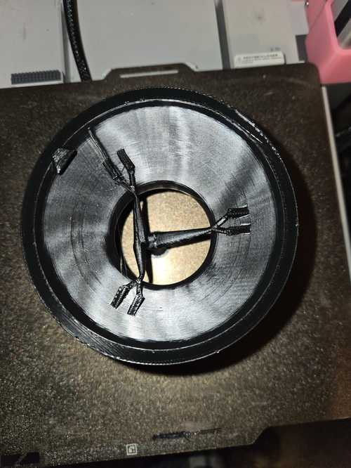
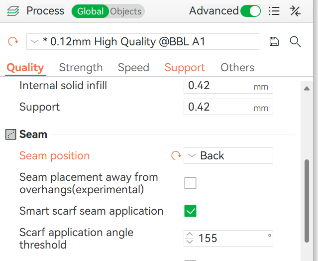
In this last print, I noticed a while line in the front of my print and using the legend, figured out that it was a seam. I was able to move it using the seam position drop down menu, and changing it to back.
Computer Controlled Cutting
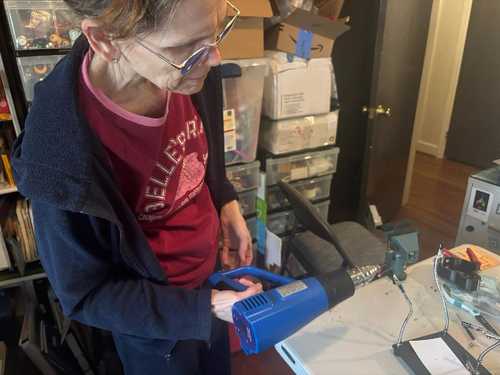
I used the laser cutter to make the top pf the cartridge lid that will swing open.
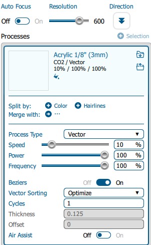
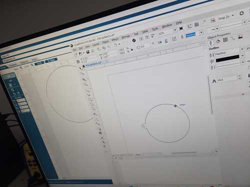
I cut my lid on the laser at the lab. Our laser with the picture line up was being repaired, so I used the older laser that you manually align. I brought my lid file in corel draw on the laser computer from an SVG off the fusion file. I used the epilog settings for Acrylic.
When it ran on the laser, Collin Kanofsky pointed out that the laser was running twice in certain areas but not others. So I needed to modify the corel file to remove the overlapping lines.
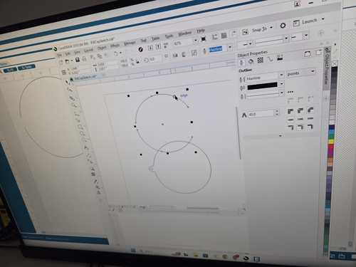
It wasn't cutting through so we needed to run it multiple times. When trying to adjust our cut path, I moved the part in the file and then it cut through the wrong part.
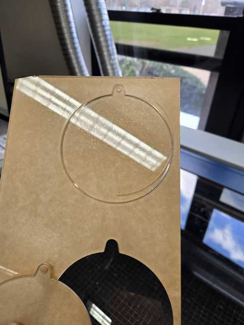
I separated the two and then deleted the extra and then ran it again over 3 inches to a clean spot. I had to run the cut multiple times to cut through. Possible dirty lense?
Electronics Design
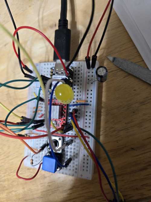
I started working on the stepper motor and the electronics design with a tutorial. I used first the RP 2040 and then did it again with the ESP32C6. In the end, I went with the XIAO ESP32C6 to move forward with my project.
I used a breadboard to start laying it out to see if it would work.
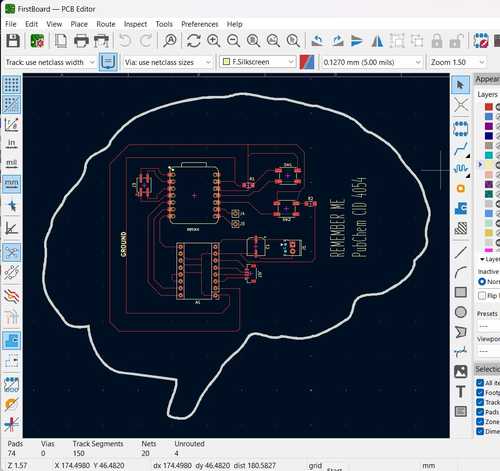
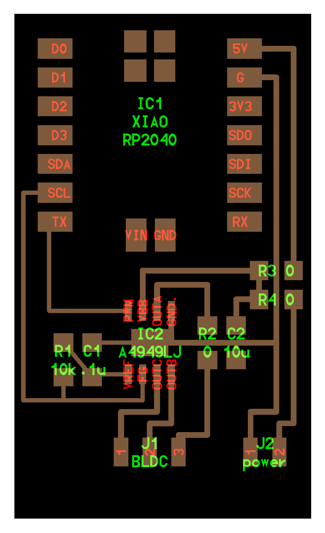
During our electronics design week, I designed a board that I could use in the final project. I may need to make it smaller or change the shape if I want it to fit into my project. or it can be on the side since it fits the theme.
Noise Reduction Using Capacitors
There was much discussion at open time about the capacitors. What is the required amount and how do you know. Neils suggestion is 100uF.

Neil's page with 100 uF capacitor
Ricardo Marques also commented in open time that 100 is the standard, but I may be ok with less in my project with the low current and voltage.
Computer Controlled Machining
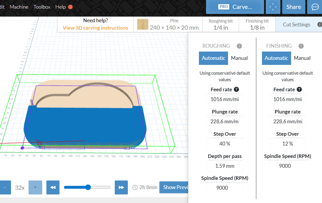
I'd like to make my base for my pill dispenser from wood for aesthetics.
I did some preliminary work in easel, but ran out of time during the CCM week, hopefully I will get back to it.
Electronics Production
During our electronics design week, we learned to mill boards. My final board had a smaller shape than the original cool brain to fit into the machine, but a similar component layout.
I'm using the board that I milled in week10 but didn't finish that week.
Soldering
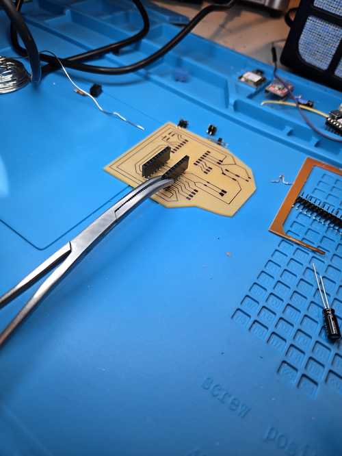
Classmate Dorian Fritze sent me a link to these medical grabbers that lock. They were a COMPLETE game changer for soldering.
I laid out my components and got to work.
Drilling
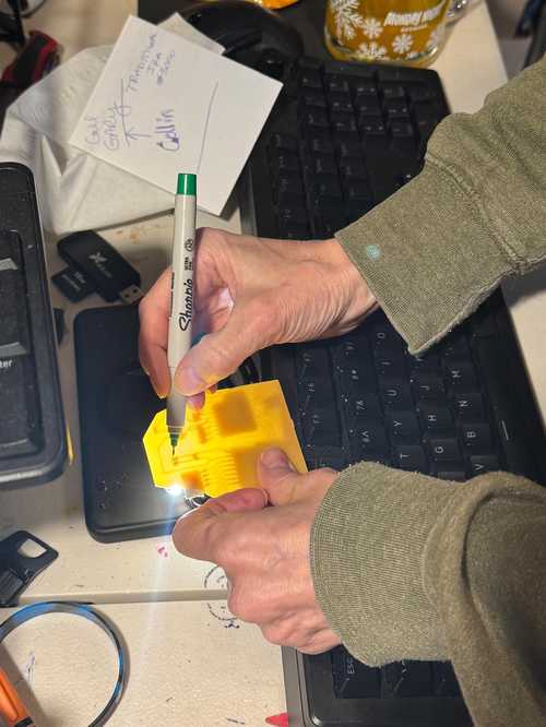
I manually attached the power connector. I used a trick from Collin Kanofsky by putting the phone as a flashlight to locate my traces and mark out where I wanted to drill.
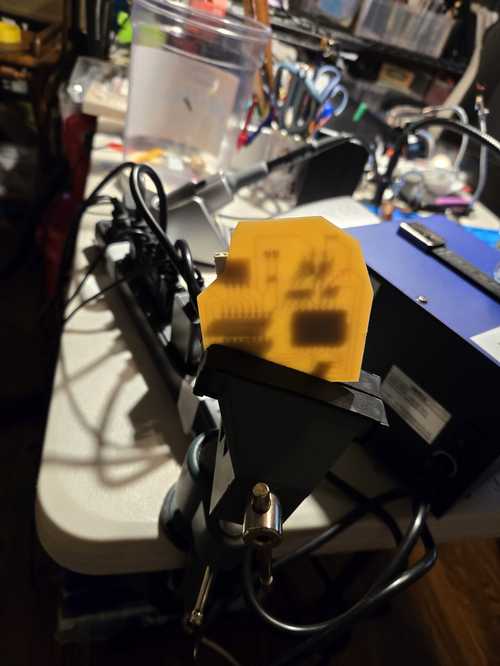
Then I put the board in a vice and drilled with the smallest bit I had, which was unfortunately a 1/16th - still pretty big. but worked.
Testing Lots of Testing
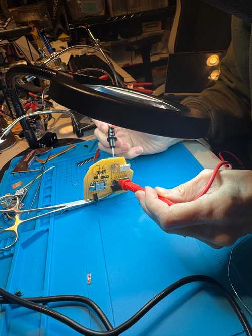
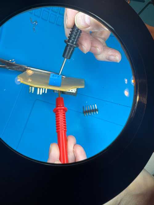
I used the multimeter in continuity mode to test test and test some more.. every connection, and every gpio to each other. I found that I had some solder bridging and had to go back in and clean it up so there would not be connections where I didn't want them.
NEMA 8 Stepper Motor
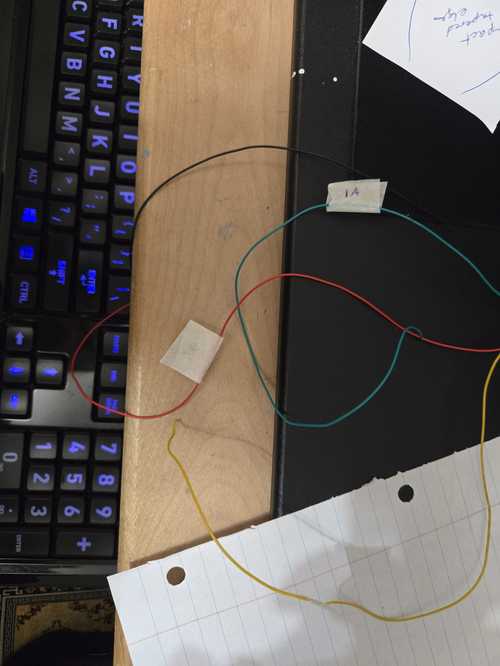
Following the same tutorial that Mr. Dubick sent, I tried the twist test on the four wires that connect the stepper motor to figure out which two wires of my NEMA8 are a pair.
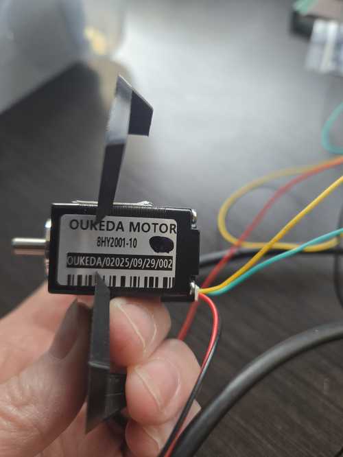
When the twist was clicky, those were a pair compaired to smooth when you turn the motor shaft. This wasn't convincing for me so I to find the phases using the multimeter. Continuity testing will determine theo ne phase of the motor that goes on 1A and 1B pins, and the other phase on 2A and 2B pins.
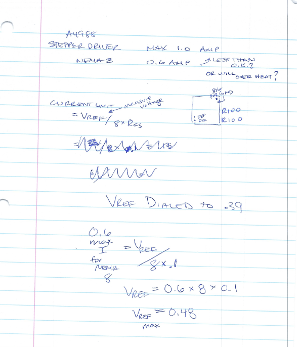
A4988 Motor Driver Current Limiting
I need to adjust the current limit of the driver to be lower than the current rating of the motor, so that the motor will NOT overheat.
I hooked everything up. It took me a really long time because I was really worried about the 12V current and making sure that I didn't mess anything up (i.e. burn up the chip especially after how long it took me to mill the board and solder everything on).
I found the tiny sense resistors on the 4988 and they were 100mOhm (I would use .1 in my calculations). They connect to the motor coils.
I then measured the Vref reading by measuring over the potentiomer to the ground with a multimeter set to Voltage reading. The below picture from the tutorial was really helpful.
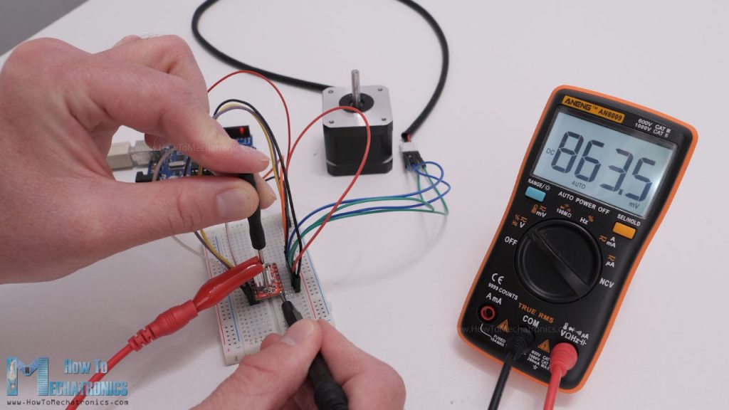
I turned the potentiomer to be less than my calculated Vref for a 0.6 max Amp motor. This meant that it should read ~0.39 for my project.
Photoresistor
To incorporate the photo resistor, I had to put heat shrink around one leg so they didnt touch in the tunnel. Then on the ends, I used an extension to connect to the board. One one end of the extension, I used the shrink wrap tube with solder into it to extend it.
I decided to try traditional soldering for the other end becuase I worried about the heat gun melting my 3D printed part.
Two Buck Chuck
I have two power sources coming from device. One from the chip and another powering the motor. I did some research and it sonds like I need a to use a small DC-DC buck converter to step it down to 5V for the XIAO. So I will split the currnt coming using another little chip that I will mill and then have a buck on it and two outputs.. a 12V (power to the motor) and a 5V (power to the chip).
Embedded programming
I started with the codes I had made in the weeks coming up to combine together to make the code. I have the following code pieces:
- code that turns on and off light a light from a browser on my phone
- code that reads the light value from my photo resistor and then takes an action
- code that spins a stepper motor 1/8 a turn
I used a series of prompts and then took pieces from each to keep modifying my initial code working towards a final code.
Motor Programming
I have started working on programming a motor to move in steps. I need 8 steps per revolution to match my design. I found some documentation to help me with the arduino stepper library. For the example motor I have from my ELEGOO kit.. its 2048/8. I have another motor that i want to try that I got from the lab. More research is needed.
I started learning using the stepper.h library but the A4982 doesn't work that way. It only wants a STEP pulse and a DIR signal. So my code uses delayMicroseconds(1000) to set up step pulse timing. I found that 20,000 had it spinning too fast and at 8,000 it was missing steps. I ended with delays 15,000 and that worked well. It's a bit jerky. The fix for that is microstepping, but that will be in V2 becuase I grounded my microsteppers on the PCB under my chip. The stepping will work accurately enough for what I need in V1.
Prompts and converstaion with AI to learn about how to diagnose and tune in my motor, my motor driver and issues can be found here. I learned that a warm motor was ok. Its caused by the Current limit (Vref) too high can make it hotter. IF its not moving it could be holding torque, and suggested the below code to help with that issue.
// after a move, disable the driver
digitalWrite(ENABLE_PIN, HIGH);  // HIGH = disabled on most drivers

// re-enable before next move
digitalWrite(ENABLE_PIN, LOW);
My Vref is way below my calculation. So, I incorporated that code to disable the motor, and moved on.
Another issue with the code was that my initial print line asking how many slots I wanted to turn was not coming up.. AI helped me to figure out that I needed to add a longer delay.
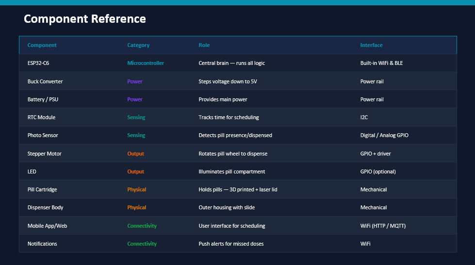
MIDTERM REVIEW REQUIREMENTS
On your final project site post - a system diagram for your project, list the tasks to be completed, - make a schedule for doing them, - meet with your local and global instructors to review these and your weekly assignments. (scheduled for 4/20/2026)
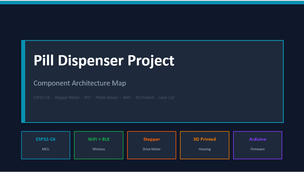
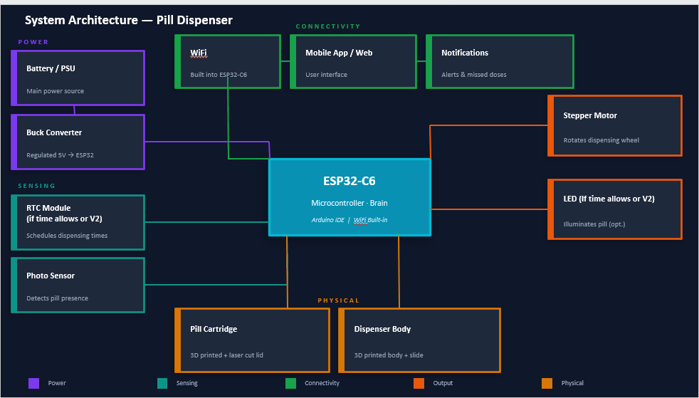
System Diagram 
Diagram
Claude Co work Assisted PROMPT: help me make A map of my pill dispenser project and all of the components - maybe in power point of google slides so i can edit it
List of things to be completed 
- Reprint 3D cartridge body, divider and stepper motor key
- test function and tune settings
- implement power splitter - buck?
- System integration
- Create code
- Create interface
- make slide
- make video
My Claude assisted Time Line is Here
PROMPT: make a gaant style time line for getting these things done by the end of May
Application Creation
I did most of my application work in week 15
System Integration
As I went to integrate my system, my board was coming apart, so I went back and worked on redesigning a more compact board and addedthe ability to connect a light to be able to dispense at all times.
Most of my packagin work was done in week 16. This is where I made my PCB board holders and figured out how everything would fit together.
Voltage
When I started, I was told to use a 12V power sourse. This is most likely becuase the A4988 motor driver data sheets specs out 8V-25V.
At open time, I got a lot of push back on why was I using the 12V, and I wasn't fast enough in the memory department to answer. They said 5V is more than enough. I worked with claude to get some feedback which can be found here.
After reading and learning, I will stick with the 5V for now.. and I am thinking about adding a regulator to my board.Everything cooled down., but the wifi seemed to have a hard time powering up. I am wondering if the power supply is a part of this. Claude thinks its electrical noise.
I wanted to understand more about how the Voltage impacts the machin so I talked some more with Claude. It can be found here. After that discussion, I decided to turn my focus to Amperage to learn more and understand more about what would be best for my system.
Amperage
I wanted to understand the Amperage needs of my system and how it was calculated (claude assisted chart).
Current Calculation at 12V
| Component | Current |
|---|---|
| Stepper motor (full step, max) | 600mA |
| A4988 logic (VDD from buck) | ~20mA |
| ESP32-C6 (WiFi active, peak) | ~500mA |
| White LED (assume 20mA) | ~20mA |
| Photoresistor | ~1mA |
| Buck converter overhead (~85% eff.) | ~15mA |
| Total worst case | ~1,156mA |
So I need a 1.5 to 2 Amp source.
After these discussions, I decided because of the voltage requirement of the motor driver and the max Amperage, I would order a 9V 2 amp power supply and work with that instead.
Testing
Light Sensor Tuning
Using the IP address an the/lightstatus in my browser, I was able to take multiple readings in different light conditions with different pills.
| Light/Pill Status | ADC Value | Threshold setting | Pill taken? |
|---|---|---|---|
| Dim Light | Raw ADC: 2400 | Threshold: 2000 | Pill taken: NO |
| Dim Light + B-12 | Raw ADC: 3317 | Threshold: 2000 | Pill taken: NO |
| Dim Light + Lysine | Raw ADC: 3299 | Threshold: 2000 | Pill taken: NO |
| Dim Light + Zyrtec | Raw ADC: 3206 | Threshold: 2000 | Pill taken: NO |
| Bright Light | Raw ADC: 946 | Threshold: 2000 | Pill taken: YES |
| Bright Light + Zyrtec | Raw ADC: 2919 | Threshold: 2000 | Pill taken: NO |
| Bright Light + Zyrtec2 | Raw ADC: 2943 | Threshold: 2000 | Pill taken: NO |
| Bright Light + Lysine | Raw ADC: 2739 | Threshold: 2000 | Pill taken: NO |
| Bright Light + B-12 | Raw ADC: 3256 | Threshold: 2000 | Pill taken: NO |
2000 Threshold is too low. Maybe closer to 2600… would be more reasonable.
However, I decided to add a light and the pill catcher and now I need to run these tests again.. LOL.