Set Up for milling 3D on the Genmitsu in Fusion 360
After trying every machine in the lab, I came home and decided to try the beeswax on the Genmitsu machine at home.
Here is a Youtube to eatch from LynxPilot which also shows a process to mill on a genmitsu on the 3018
PROMPT: Explain these settings. I am in fusion 360 build v.2702.1.58 (April 23)
setup Machine tab
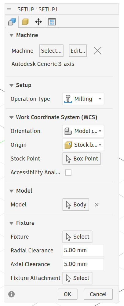
This is the Setup tab 1 — the main setup panel. Let's go through each section:
MACHINE
Shows "Makera Carvera 3-axis Communi..." — this is a machine configuration that was previously selected. For your Genmitsu 3018 you'd want to either: - Click Select to pick a different machine from the library (search "grbl" or "generic 3-axis") - Click Edit to modify the current one - Click the X to remove it and run without a machine config (totally fine for the 3018 — machine config is optional)
SETUP
Operation Type dropdown: - Milling — rotating tool cuts material (what you want) - Turning — lathe operations, ignore - Mill/Turn — combined, ignore - Jet Cutting — laser/plasma/waterjet, ignore
Leave this on Milling.
WORK COORDINATE SYSTEM (WCS)
This is the most important section.
Orientation dropdown: - Model orientation — WCS axes align with your model's axes. Usually the right choice if your model was built upright - Select Z axis/plane — you manually pick a face to define which way Z points. Use this if your model is oriented oddly - Select X/Y/Z axes — full manual control of all three axes - Select points — define orientation by picking three points
For most imports, Model orientation works fine. If your part comes in sideways after importing the STEP, use Select Z axis/plane and click the top face.
Orientation — IF not already selected, Select Z axis/plane then click the top face of your part/stock. This tells Fusion which direction is "up" and reorients everything so Z points upward out of the table.
Origin dropdown: - Stock box point — zero is on the bounding box of your stock material ✓ recommended - Model box point — zero is on the bounding box of the model geometry - Model origin — uses the 0,0,0 from the original CAD file - Selected point — you click a specific point manually - Fixture box point — based on fixture geometry, ignore for 3018
Stock box point is what you want — matches your physical workflow of zeroing at a corner of raw material.
Stock Point → Box Point The 3x3 grid picker. After setting Origin to Stock box point, this lets you pick which of the 9 points on the stock bounding box is your zero. Click it and you'll see the grid — top-left-front corner is the most common choice for the 3018.
Accessibility Analysis checkbox Runs a color analysis showing which surfaces are reachable by your tool from above. Useful for complex 3D parts, not needed for simple 2.5D milling. Leave unchecked.
MODEL
Model → Body This tells Fusion which body to generate toolpaths for. "Body" means it's using the solid body in your design. If you had multiple bodies you could select a specific one. Leave as is.
FIXTURE
All ignorable for the 3018.
Fixture → Select — for modeling a vise or clamp so Fusion can do collision avoidance. Not needed unless you've modeled your workholding.
Radial Clearance 5.00mm — how far sideways the tool stays from fixture geometry. Only matters if a fixture is defined.
Axial Clearance 5.00mm — how far above fixture geometry the tool stays. Same — only matters with a fixture.
Fixture Attachment → Select — defines how the fixture connects to the table. Ignore.
Stock tab
This is the Stock tab — it defines the raw block of material you're physically cutting. The red-highlighted fields mean the stock is currently smaller than the model, which is a problem.
NOTE: HERE I changed the model to be smaller than the stock, then meansured my stock with a caliper and re-entered all the dimensions.
STOCK
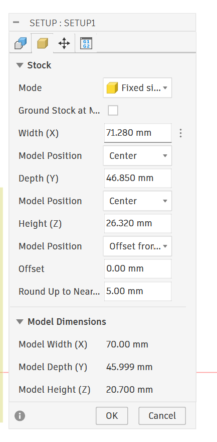
Mode dropdown: - Fixed size — you manually type in exact stock dimensions. What's currently selected.
Note: I think We have to use this becuase we actually ahve a fixed stock size.
- Relative size box — adds a specified amount of extra material around the model on all sides (e.g. 1mm extra everywhere). Good for leaving finishing allowance
- From solid — uses another body in your design as the stock shape. For oddly shaped raw stock
- No stock — no stock defined, simulation won't show material removal
Fixed size is fine for the 3018 — you know exactly how big your material is, just type it in.
Ground Stock at M... (checkbox) "Ground Stock at Machine WCS" — forces the bottom of the stock to sit at Z0. Leave unchecked for normal use.
Width (X) — 70.800mm ⚠️ The X dimension of your stock. This is highlighted red because your Model Width below is 76.200mm — your stock is narrower than the model. You need to increase this to at least 76.200mm, or whatever your actual physical material width is.
Model Position (X) → Center dropdown: - Center — model sits centered left-right within the stock - Minimum — model sits at the left edge of stock - Maximum — model sits at the right edge of stock - Offset — model sits at a custom offset from stock edge
Center means equal material on both sides of the model in X.
Depth (Y) — 48.200mm ⚠️ Same issue — Model Depth is 50.800mm, stock is shallower. Increase to match or exceed your actual material depth.
Model Position (Y) → Center — same options as X above, same meaning.
Height (Z) — 24.00mm The thickness of your stock material. This one looks close to the model height of 24.130mm so probably fine, but bump it slightly to be safe.
Model Position (Z) → Offset from... dropdown: - Offset from bottom — model sits a specified distance up from the bottom of stock - Offset from top — model sits a specified distance down from top of stock - Center — model centered vertically in stock
For milling you almost always want Offset from top at 0.00mm — meaning the top of your model is flush with the top of your stock. That's your Z zero surface.
Offset — 0.00mm The actual offset value for whatever Model Position Z is set to.
Round Up to Nearest — 10.00mm Rounds stock dimensions up to the nearest 10mm increment. So if your model is 76.2mm wide, stock rounds up to 80mm. Convenient but can give you more stock than you actually have — for fixed size mode you're typing exact numbers anyway so this matters less.
MODEL DIMENSIONS (read-only, for reference) - Model Width (X): 76.200mm - Model Depth (Y): 50.800mm - Model Height (Z): 24.130mm
These are the actual dimensions of your imported body. Your stock needs to be equal to or larger than all three of these numbers.
Setup → Part Position
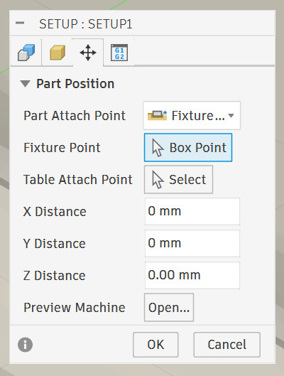
This is the Setup → Part Position tab in Fusion 360's Manufacturing workspace. It defines how your part is positioned relative to the machine table.
Part Attach Point
Set to "Model I..." (Model Inventory Origin or similar). This is the reference point on your machine/table side — where the machine thinks the part will sit.
This is the Setup → Part Position tab in Fusion 360's Manufacturing workspace. It defines how your part is positioned relative to the machine table.
Model Point → Box Point This is the key one. "Box Point" means Fusion will let you pick one of the 9 points on the bounding box of your part (corners, edge midpoints, or center) as your WCS zero. When you click Box Point, you'll see a 3x3 grid of dots appear on the part — you click which corner/point becomes your X0 Y0 Z0. Most common choice is top-left-front corner or bottom-left-front corner.
Table Attach Point → Select This is where on the machine table that Model Point will land. Usually left as the default unless you have a specific fixture or offset.
DIVING DEEP HERE BECUASE THIS WAS CONFUSING:
PROMPT: with the table attach mpoint - is this on the machine table or the same as the model point box point that we chose earlier on the top left front?
Good question. They are two different things working together like a mating pair:
Model Point (Box Point) This is a point on your part/stock. It's saying "this corner of my material is the reference point."
Table Attach Point This is a point on the machine table. It's saying "place my Model Point here on the table."
How they work together
Think of it like a snap/mate:
"Take this point on my stock → and place it at this point on my table"
They snap together. Model Point lands on Table Attach Point.
Why it doesn't matter for your 3018
When Table Attach Point is left at Select (nothing chosen), Fusion essentially says "I don't know or care exactly where on the table the part sits — the operator will set that manually."
That's exactly your workflow: - You plop your material somewhere on the spoilboard - You jog to the corner in Candle - You zero there
You're physically performing the "snap" yourself by zeroing the machine. Fusion doesn't need to know where on the table it landed because you're telling the machine directly by setting WCS zero in Candle.
Table Attach Point only becomes useful when you have a fixture plate with known hole positions and the machine always knows exactly where the part is without manual zeroing.
**X Distance / Y Distance ** Offsets the part in X and Y from the attach point. This is likely auto-calculated from your bounding box, or you can type in a manual offset if you need to shift the part on the table.
Z Distance — 0.00 mm No Z offset — your Z zero is flush with whatever point you selected. For milling you almost always want this at the top surface of your stock.
For your 3018 workflow: The most important thing here is making sure your Box Point selection matches where you physically zero your machine in Candle. If you zero at the top-left corner of your material, pick that same corner here.
Model Point → Box Point
This is the key one. "Box Point" means Fusion will let you pick one of the 9 points on the bounding box of your part (corners, edge midpoints, or center) as your WCS zero. When you click Box Point, you'll see a 3x3 grid of dots appear on the part — you click which corner/point becomes your X0 Y0 Z0. Most common choice is top-left-front corner or bottom-left-front corner.
Note: WCS = Work Coordinate System It's the "you are here" reference point that everything in your job is measured from.
Table Attach Point → Select
This is where on the machine table that Model Point will land. Usually left as the default unless you have a specific fixture or offset.
PROMPT: telll me more about setting this
Honestly, for the Genmitsu 3018 you can ignore Table Attach Point entirely — just leave it at default. Here's why:
What it actually does
Table Attach Point defines a specific location on your machine table where the Model Point will be placed. It's essentially saying "place my part's zero point at this exact spot on the physical table."
It's designed for production CNC setups where: - You have a fixture plate with known, repeatable hole patterns - You run the same job repeatedly and always clamp the part in the exact same spot - Your CAM setup needs to know the part is always at, say, X200 Y150 from machine home
The two modes
Left as default (no selection) Fusion just places the part at the machine origin conceptually. Your WCS zero in the G-code comes out as G54 at 0,0,0. This is what you want — you then physically set your zero in Candle by jogging to your material corner.
With a point selected You're telling Fusion the part will always live at a specific known coordinate on the table. The G-code gets baked-in offsets to account for that location. Useful if you have a dedicated spoilboard with threaded inserts at known positions.
Why it doesn't matter for your 3018
Your workflow is: 1. Clamp material somewhere on the spoilboard 2. Jog to the corner in Candle 3. Zero there manually
You never know ahead of time exactly where on the table the material will land — and you don't need to, because you're setting zero manually each time. Table Attach Point is for machines where the part location is predetermined and repeatable without manual zeroing.
Leave it alone and set your zero in Candle as usual.
X,Y,Z OFFSETS
**X Distance / Y Distance ** Offsets the part in X and Y from the attach point. This is likely auto-calculated from your bounding box, or you can type in a manual offset if you need to shift the part on the table.
Z Distance — 0.00 mm No Z offset — your Z zero is flush with whatever point you selected. For milling you almost always want this at the top surface of your stock.
For your 3018 workflow: The most important thing here is making sure your Box Point selection matches where you physically zero your machine in Candle. If you zero at the top-left corner of your material, pick that same corner here.
Milling Beeswax
PROMPT: show me feeds and speeds for milling beeswax on the genmitsu - show your sources
Recommended Starting Settings for Pure Beeswax on the Genmitsu 3018
| Parameter | 3mm (1/8") Flat End Mill | 1.5mm (1/16") Flat End Mill |
|---|---|---|
| Spindle speed | 8,000 RPM (S~975 in Candle) | 8,000 RPM (S~975) |
| Feed rate | 800–1000 mm/min | 500–700 mm/min |
| Plunge rate | 200–300 mm/min | 150–200 mm/min |
| Pass depth | 1.0–1.5mm | 0.5–0.8mm |
| Stepover | 40% of diameter | 40% of diameter |
Key Beeswax-Specific Warnings
Heat is your enemy — beeswax melts around 63°C. If you go too slow (rubbing instead of cutting), friction heat will gum up your bit with melted wax almost instantly. Pure beeswax is less forgiving than machinable wax. Keep feed rate up to ensure actual cutting.
Chip clearing — melted wax chips weld back to the surface. Use compressed air if you have it, or pause to clear chips frequently.
Run spindle at full speed — on such a soft material, max RPM on the 3018 is fine and helps avoid rubbing.
Do a test pass first — start at the lower end of the feed range and listen. If you hear rubbing/squealing, speed up the feed. If the machine stutters, slow it down.
Pocket Cut 3D
PROMPT: lets talk about these settings - I am trying to mill the beeswax with a 1/8 ball nose end mill
Tool
This is the Tool tab of a Pocket operation. Let's go through everything and I'll tell you what to change for beeswax with that 1/8" ball nose.
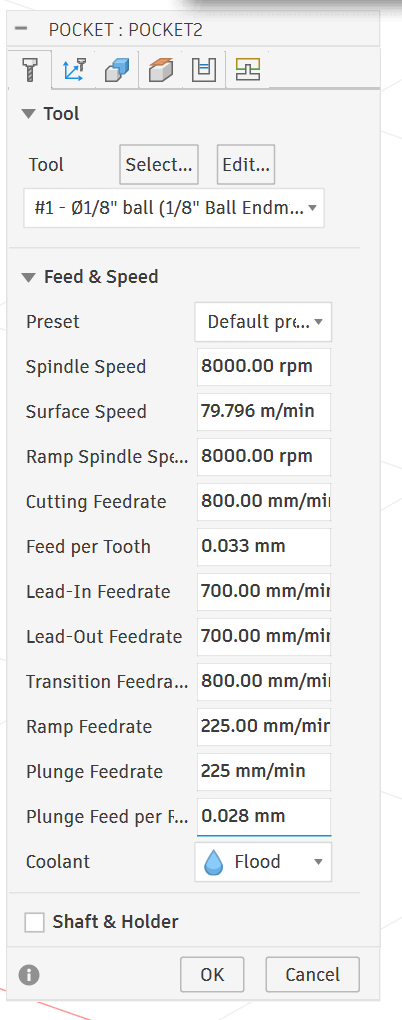
TOOL
Currently set to #1 - Ø1/8" ball (1/8" Ball Endmill) — correct tool selected, good.
FEED & SPEED
Preset → Default pre... This is pulling default values from the tool library, which is why your numbers aren't dialed in for beeswax. You'll override these manually.
Spindle Speed — 5000 RPM ⚠️ Too low for beeswax on the 3018. Change to 8000 RPM (which is close to your machine's max). Low RPM on soft waxy material causes rubbing and melting instead of cutting.
Surface Speed — 49.873 m/min This is calculated automatically from spindle speed and tool diameter. It will update when you change RPM. You don't edit this directly.
Ramp Spindle Speed — 5000 RPM ⚠️ Match this to your spindle speed. Change to 8000 RPM.
Cutting Feedrate — 1000 mm/min (the field appears truncated but likely shows 1000) For a 1/8" ball nose in beeswax this is reasonable. Set to 800–1000 mm/min — start at 800 and work up.
Feed per Tooth — 0.067 mm This is calculated from feedrate ÷ (RPM × flutes). It will update automatically. For reference a 1/8" ball nose in wax wants roughly 0.05–0.08mm per tooth, so this is in range.
Lead-In Feedrate ⚠️ The truncated value appears to show 1000 mm/min. Should be 10–30% slower than cutting feedrate — set to around 700 mm/min.
Lead-Out Feedrate ⚠️ Same as Lead-In — set to 700 mm/min.
Transition Feedrate The speed between cuts when the tool is repositioning at safe height. Can match cutting feedrate — 800–1000 mm/min is fine.
Ramp Feedrate — 333 mm/min This is the helical/ramp entry speed into the material. For beeswax this is actually fine — the ball nose handles ramp entry well. You could bump to 400 mm/min if you want.
Plunge Feedrate — 33.333 mm/min ⚠️ Way too slow — this will cause rubbing and heat buildup on entry. Change to 200–250 mm/min for beeswax.
Plunge Feed per Flute — 0.067 mm Updates automatically from plunge feedrate. Fine.
Coolant → Flood ⚠️ The 3018 has no coolant system. Change this to Disabled. Flood coolant would also dissolve/contaminate beeswax anyway. Leave it dry — chip clearing with air or a brush is your only option.
SHAFT & HOLDER Leave unchecked unless you've modeled your collet — not needed for the 3018.
Summary of changes to make:
| Parameter | Current | Change To |
|---|---|---|
| Spindle Speed | 5000 RPM | 8000 RPM |
| Ramp Spindle Speed | 5000 RPM | 8000 RPM |
| Cutting Feedrate | ~1000 mm/min | 800 mm/min (start here) |
| Lead-In Feedrate | ~1000 mm/min | 700 mm/min |
| Lead-Out Feedrate | ~1000 mm/min | 700 mm/min |
| Plunge Feedrate | 33 mm/min | 200 mm/min |
| Coolant | Flood | Disabled |
Geometry tab
This is the Geometry tab of your Pocket operation. Let's go through each section:
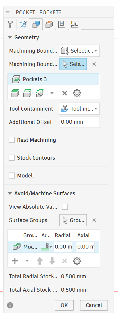
GEOMETRY
Machining Boundary → Bounding... Defines what area the toolpath stays within. The dropdown options are: - Bounding box — toolpath covers the full bounding box of the selected geometry - Selection — you pick specific edges or faces to define the boundary
**NOTE: I chose the bottom face inside of my box for the boundary.
- Silhouette — uses the outer profile of the model as the boundary
For a pocket operation on beeswax, Bounding box is fine for roughing. If you want to machine only a specific region, switch to Selection and pick the pocket faces.
Selection Box
Lets dive Deep in the Selection Tool - Yes, exactly right. That dropdown is the boundary selection type — it defines what kind of geometry you're selecting to define your machining boundary.
For what you're describing — bottom face of the model and inside the gear shape — here's which one to pick:
Use: Pockets
This is the right choice for your situation. It automatically recognizes closed pocket regions — like the inside of a gear profile — and uses those as the machining boundary. It will find the inner gear shape and constrain the toolpath to stay inside it.
The other options explained:
Chain — you manually click individual edges to chain together a boundary. More work, use when Fusion can't auto-detect the shape.
Face Contours — uses the outer contour/silhouette of a selected face. Good for boundary following a curved or irregular face edge.
Pockets — auto-detects closed pocket regions from selected faces. ✓ Your best choice here.
Pocket Recognition — similar to Pockets but with more automatic detection across the whole model. Can sometimes grab regions you don't want.
Silhouette — uses the outer shadow/profile of the model from above. More useful for outside profiles than inside pockets.
Sketch Profiles — lets you use a 2D sketch you drew as the boundary. Use this if nothing else captures your shape correctly.
Your workflow: 1. Select Pockets from that dropdown 2. Click the bottom face of your gear shape in the viewport 3. Fusion should highlight the inner gear profile as the boundary 4. Confirm it's selected correctly before hitting OK
Tool Containment → Tool cel...(center)
Controls how the tool relates to the boundary edge. Options are: - Tool center on boundary — center of tool travels exactly on the boundary line - Tool inside boundary — entire tool stays inside — leaves a small uncut edge equal to tool radius - Tool outside boundary — tool center goes outside the boundary
For a pocket Tool inside boundary is usually correct — keeps the full tool diameter within your pocket walls. Worth checking this is set that way.
Additional Offset — 0.00 mm Shrinks or expands the machining boundary by this amount. Leave at 0 for now.
REST MACHINING ✓ (checked) ⚠️
This is enabled and worth paying attention to. Rest machining tells Fusion to only cut material that a previous larger tool left behind — it assumes a prior roughing pass was done and skips already-cleared areas.
NOTE: I turned this off/ unchecked the box. I dont have a previous pass. This is my roughing pass.
Source → From pr... (From previous operation) It's referencing a previous toolpath as the "already cut" baseline.
Ignore Stock Less Than — 0.200 mm Ignores remaining stock thinner than 0.2mm — prevents tiny unnecessary passes.
Reduce Air Cutting ✓ Skips moves where the tool would just be moving through air. Good, leave this checked.
For your situation: If this is your first and only operation with no prior roughing pass, uncheck Rest Machining. Otherwise Fusion may skip large areas thinking they were already cut, and your pocket won't get machined.
STOCK CONTOURS — unchecked
Limits toolpath to within the stock boundary. Fine to leave unchecked.
MODEL — unchecked
Would limit the toolpath based on the model geometry in a specific way. Leave unchecked for a standard pocket.
AVOID/MACHINE SURFACES
This lets you designate surfaces the tool should avoid or specifically machine.
Surface Groups shows one entry: - Moc... (Model) with 0.00mm Radial and Axial offsets
This means the model surfaces themselves are in the avoidance/machine list with no offset — essentially telling the tool to machine right to the model surface with no stock left.
Total Radial Stock — 0.500 mm ⚠️ This means 0.5mm of material is being left on vertical walls. For a finishing pass that's too much. For a roughing pass it's intentional — you'd follow up with a finish pass to remove that last 0.5mm. Decide if this is roughing or finishing: - Roughing → 0.5mm is fine, plan a finish pass after - Finishing → change to 0.00mm
Total Axial Stock — 0.500 mm ⚠️ Same — 0.5mm left on floor/bottom surfaces. Same logic applies.
Summary of things to check:
| Setting | Current | Action |
|---|---|---|
| Rest Machining | Enabled | Disable if this is your first/only pass |
| Tool Containment | Tool center | Verify it's set to Tool inside boundary |
| Total Radial Stock | 0.500mm | Set to 0 if finishing, keep if roughing |
| Total Axial Stock | 0.500mm | Set to 0 if finishing, keep if roughing |
Is this meant to be a roughing pass or the final finishing pass on the beeswax?
Heights tab
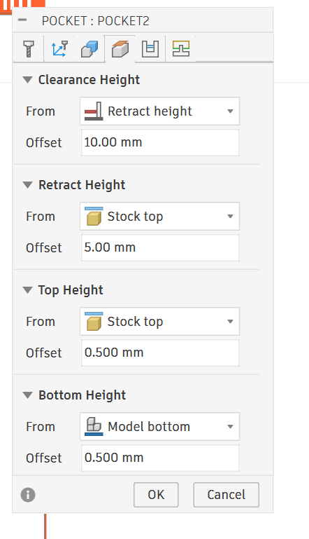
This is the Heights tab — it controls where the tool travels vertically. This is the tab that matters most for the 3018 since your Z travel is limited. Let's go through each:
CLEARANCE HEIGHT From: Retract height | Offset: 10.00mm The highest Z position the tool travels to when making large rapid moves across the part. It's 10mm above the retract height. For the 3018 this could be problematic — stacked offsets can push Z too high and trigger your limit switch. Watch this one.
RETRACT HEIGHT From: Stock top | Offset: 5.00mm Where the tool pulls up to between cuts. 5mm above the top of your stock. This is reasonable but on the 3018 you can often reduce this to 2–3mm to keep Z travel conservative and avoid hitting the upper limit switch.
TOP HEIGHT From: Stock top | Offset: 0.500mm Where the toolpath starts cutting from — 0.5mm above stock top. This gives the tool a little air before it touches material on the first pass. 0.5mm is fine, you could reduce to 0.1mm to save a tiny bit of time but it's not critical.
BOTTOM HEIGHT From: Model bottom | Offset: 0.500mm ⚠️ This is important — it means the tool stops 0.5mm above the model bottom. This is correct behavior for a roughing pass — it intentionally leaves 0.5mm of floor material matching the Axial Stock you set on the Geometry tab.
Summary for your 3018:
| Setting | Current | Recommendation |
|---|---|---|
| Clearance Height | Retract + 10mm | Reduce offset to 3–4mm |
| Retract Height | Stock top + 5mm | Reduce to 2–3mm |
| Top Height | Stock top + 0.5mm | Fine as-is |
| Bottom Height | Model bottom + 0.5mm | Correct for roughing ✓ |
The main concern is keeping Clearance and Retract heights low enough that your Z axis doesn't slam into the upper limit switch mid-job. On the 3018 with its shallow Z travel, stacked heights add up fast.
This is the Passes tab — controls how the tool moves through the material. Let's go through everything:
PASSES
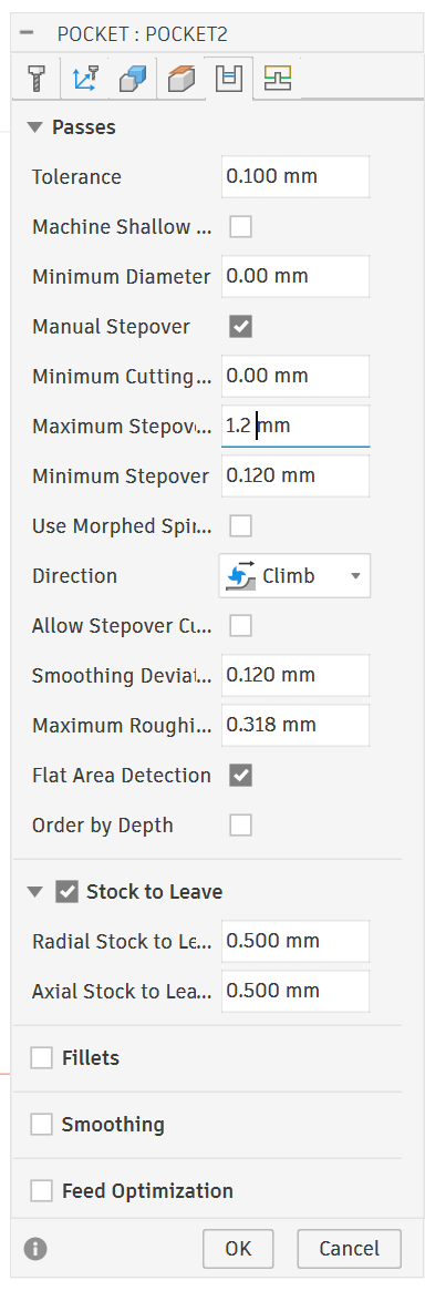
Tolerance — 0.100mm How closely the toolpath follows the model geometry. 0.1mm is fine for roughing. For finishing you'd tighten to 0.01mm. Leave as-is for roughing.
Machine Shallow Areas — unchecked Adds extra passes in areas with shallow slopes. Not needed for roughing, leave unchecked.
Minimum Diameter — 0.00mm Ignores pocket features smaller than this diameter. 0.00mm means nothing gets ignored. Fine.
Manual Stepover ✓ — checked You're manually controlling stepover rather than letting Fusion calculate it. Good — keeps you in control.
Minimum Cutting — 0.00mm Minimum width of material the tool will attempt to cut. Leave at 0.
Maximum Stepover — 1.905mm ⚠️ This is 75% of your 1/8" (3.175mm) tool diameter. For roughing beeswax that's aggressive given the 3018's limited rigidity. Reduce to 1.2–1.5mm (about 40–50% of diameter).
Minimum Stepover — 0.191mm The smallest stepover Fusion will use in tight areas. Fine, leave it.
Use Morphed Spiral — unchecked Alternative toolpath pattern that morphs between the pocket boundary and center. Not needed, leave unchecked.
Direction → Climb ✓ Climb milling is correct for beeswax — it produces cleaner cuts and less heat than conventional. Leave this.
Allow Stepover Cuts — unchecked Allows extra cuts at the stepover transition. Not needed, leave unchecked.
Smoothing Deviation — 0.191mm How much the toolpath can deviate from ideal to create smoother motion. Fine for roughing.
Maximum Roughing Stepdown — 0.318mm ⚠️ This is your pass depth — how deep each Z layer cuts. 0.318mm is actually reasonable for beeswax roughing with a 1/8" ball nose. You could go up to 0.5mm for faster material removal since beeswax is so soft, but 0.318mm is safe to start.
Flat Area Detection ✓ — checked Fusion adds extra passes on flat horizontal areas to ensure they get properly machined. Good, leave checked.
Order by Depth — unchecked Machines all features at one depth before moving to the next. Leave unchecked for standard pocket roughing.
STOCK TO LEAVE ✓
Radial Stock to Leave — 0.500mm ✓ Leaves 0.5mm on walls for finishing pass. Correct for roughing.
Axial Stock to Leave — 0.500mm ✓ Leaves 0.5mm on floor for finishing pass. Correct for roughing.
FILLETS — unchecked Adds fillet toolpaths at floor/wall intersections. Not needed for roughing.
SMOOTHING — unchecked Smooths toolpath motion. More useful for finishing. Leave off for roughing.
FEED OPTIMIZATION — unchecked Adjusts feedrate automatically based on engagement. Useful feature but adds complexity — leave off until you're comfortable with the basics.
Summary of changes:
| Setting | Current | Change To |
|---|---|---|
| Maximum Stepover | 1.905mm | 1.2–1.5mm |
| Maximum Roughing Stepdown | 0.318mm | 0.318–0.5mm (your call) |
| Everything else | Various | Leave as-is ✓ |
The stepover is the main thing to bring down. Everything else is reasonable for a roughing pass on beeswax.
This is the Linking tab — controls how the tool moves between cuts, enters, and exits the material. Let's go through it:
LINKING
Retraction Policy → Full ret...(Full Retract) Tool retracts fully to retract height between every cut. Safe choice for the 3018, keeps things predictable. Options are: - Full retract — goes all the way up to retract height every time ✓ - Minimum retract — only lifts enough to clear the stock, faster but riskier on a flexy machine - No retract — stays at cut depth, only for very specific situations
Leave as Full retract for the 3018.
High Feedrate Mode → Preserv...(Preserve rapid moves) Keeps rapid G0 moves in the G-code rather than converting them to feed moves. Leave as-is — GRBL handles rapids fine.
Allow Rapid Retract ✓ Lets the tool retract at rapid speed rather than feed speed. Good, keeps job time down. Leave checked.
Safe Distance — 1.317mm Minimum clearance above stock before the tool slows from rapid to feed speed. Fine as-is.
Maximum Stay-Down Distance — 15.875mm If the next cut is within this distance, the tool stays down and moves at feedrate rather than retracting. Reduces unnecessary retracts for nearby cuts. 15.875mm is reasonable.
Lift Height — 0.00mm Extra height added when staying down between cuts. 0.00mm is fine.
LEADS & TRANSITIONS
These control how the tool enters and exits each cut — important for surface quality and avoiding plunge marks.
Horizontal Lead-In — 0.318mm Horizontal distance of the lead-in arc/move before cutting. Fine.
Vertical Lead-In Feedrate — 0.318mm Vertical component of lead-in. Fine.
Horizontal Lead-Out — 0.318mm Same as lead-in but on exit. Fine.
Vertical Lead-Out — 0.318mm Fine.
All lead values are at one tool radius (0.318mm = ~half of 1/8" tool radius) which is standard. Leave these alone.
RAMP
This is how the tool enters the material on each new Z level — very important for beeswax since straight plunging causes heat and stress.
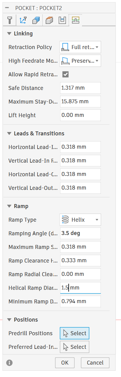
Ramp Type → Helix ✓ Tool spirals down into the material on entry. This is the best option for beeswax — distributes the entry cut over a helical path rather than plunging straight down. Leave this.
Other options are: - Profile — ramps along the profile edge - Plunge — straight down, worst for beeswax - None — no ramp at all, avoid
Ramping Angle — 2.0 deg ⚠️ The angle of the helix descent. 2 degrees is very shallow — means the tool takes a long horizontal distance to descend. For beeswax you can increase this to 3–5 degrees for faster entry without stressing the tool.
Maximum Ramp Stepdown — 0.318mm Maximum Z depth per ramp pass. Matches your pass depth, fine.
Ramp Clearance Height — 0.333mm Height above the cut where ramping begins. Fine.
Ramp Radial Clearance — 0.00mm Extra radial space for the ramp helix. Fine.
Helical Ramp Diameter — 0.794mm Diameter of the helix circle. This is about 25% of your tool diameter which is tight — could increase to 1.5–2.0mm to give the helix more room and smoother entry.
Minimum Ramp Diameter — 0.794mm Smallest helix diameter Fusion will use if space is tight. Matches helical diameter, fine.
POSITIONS
Predrill Positions → Select If you pre-drill entry holes for the helix to start in. Not needed — leave unselected.
Preferred Lead-In → Select Lets you specify a preferred entry point. Not needed, leave unselected.
Summary of changes:
| Setting | Current | Change To |
|---|---|---|
| Retraction Policy | Full retract | Leave ✓ |
| Ramp Type | Helix | Leave ✓ |
| Ramping Angle | 2.0 deg | 3–5 deg |
| Helical Ramp Diameter | 0.794mm | 1.5–2.0mm |
| Everything else | Various | Leave as-is ✓ |
Overall this tab is in good shape. The helix ramp is exactly right for beeswax — just open up the angle and diameter slightly for smoother entry.
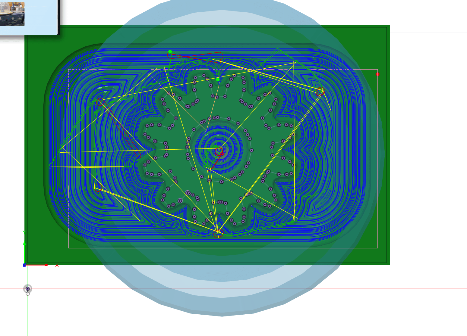
That large light blue bullseye/circle around your part is the machine tool reach visualization — it's showing the working envelope or reach radius of the machine configuration you have selected (the Makera Carvera that was loaded in your Setup).
It's not a toolpath — it's just a visual reference showing the machine's theoretical reach from the spindle center point.
Contour Path
Good — you're in the Tool tab of the Contour operation. I can see it pulled a Plastics preset which is way too aggressive for the 3018. Let's fix this tab first then I'll walk through the rest.
TOOL
1/8" ball nose is correct, keep it.
FEED & SPEED — change everything here:
| Parameter | Current | Change To |
|---|---|---|
| Preset | Plastics | leave, but override all values manually |
| Spindle Speed | 11,999 RPM | 8,000 RPM (3018 max) |
| Surface Speed | ______ RPM | Auto Adjustst to value base on above |
| Ramp Spindle Speed | 12,000 RPM | 8,000 RPM | | Cutting Feedrate | 1,589 mm/min | 800 mm/min | | Lead-In Feedrate | 1,589 mm/min | 700 mm/min | | Lead-Out Feedrate | 1,589 mm/min | 700 mm/min | | Transition Feedrate | 1,589 mm/min | 800 mm/min | | Ramp Feedrate | 1,589 mm/min | 400 mm/min | | Plunge Feedrate | 529 mm/min | 200 mm/min | | Coolant | Disabled | leave Disabled ✓ |
This is the Geometry tab for your Contour finish pass. Good news — this tab is mostly in good shape for a finishing contour. Let's go through it:
GEOMETRY on countour run
Machining Boundary → Silhouette For a contour finishing pass on a gear shape this is actually fine — it uses the outer silhouette of your model as the boundary. Fusion will follow the gear profile walls. Leave it.
Tool Containment → Tool center For a contour pass this is correct — the tool center follows the boundary line exactly, which means the full tool radius is cutting into the walls as intended. Leave it.
Additional Offset — 0.00mm ✓ No extra offset, correct for a finishing pass. Leave it.
Contact Point Boundary — unchecked Only relevant for steep/shallow filtering with ball nose. Leave unchecked.
Contact Only ✓ — checked This tells Fusion to only create toolpaths where the ball nose actually contacts the model surface. Good setting for a ball nose finishing pass — keeps the toolpath accurate to actual contact. Leave checked.
SLOPE — unchecked Would let you limit the contour pass to specific slope angles only. Not needed here — leave unchecked.
REST MACHINING — unchecked ✓ Correct — you could turn this on and point it at your roughing pass to save time, but unchecked is fine too. If you want to enable it, check the box and set Source to From previous operation pointing at POCKET2.
rest machining options
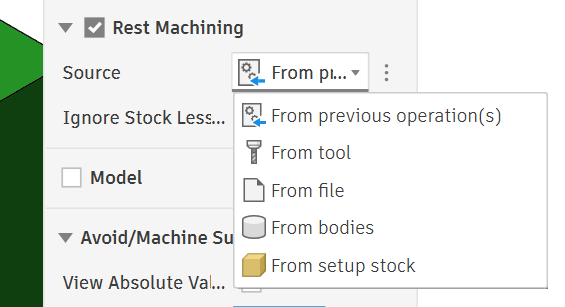
You've already checked Rest Machining and opened the Source dropdown. Here's what each option means:
From previous operation(s) ← choose this one Automatically references the operation that ran directly before this contour in your operation list — which is your POCKET2 roughing pass. Fusion knows exactly what material was left behind by that pass and only cuts the remaining 0.5mm stock. This is exactly what you want.
From tool References what a specific tool diameter would have left behind, without needing an actual previous operation. Useful if you're setting up finishing passes before you've created the roughing pass.
From file Loads a stock model from an external file. Only used in very specific multi-setup or multi-machine workflows. Ignore.
From bodies Uses a body you've modeled in Fusion as the "remaining stock" shape. Advanced workflow, not needed here.
From setup stock Uses the original raw stock block as the reference — as if nothing has been cut yet. Would make the contour pass cut everything from scratch, defeating the purpose of having a roughing pass first.
Your action: Select From previous operation(s) — Fusion will automatically link it to POCKET2 since that's the only operation before it. You don't need to manually point to it, Fusion figures it out from the operation order.
MODEL — unchecked Leave unchecked.
AVOID/MACHINE SURFACES
Total Radial Stock — 0.00mm ✓ Perfect for a finishing pass — tool goes all the way to the wall surface. Correct.
Total Axial Stock — 0.00mm ✓ Perfect for a finishing pass — tool goes all the way to the floor. Correct.
Summary:
| Setting | Current | Action |
|---|---|---|
| Machining Boundary | Silhouette | Leave ✓ |
| Tool Containment | Tool center | Leave ✓ |
| Contact Only | Checked | Leave ✓ |
| Rest Machining | Unchecked | Optional: enable and point at POCKET2 |
| Radial Stock | 0.00mm | Correct ✓ |
| Axial Stock | 0.00mm | Correct ✓ |
Height Tab
This is the Heights tab for your Contour finish pass. Comparing to your roughing pass heights, a few things have changed:
CLEARANCE HEIGHT From: Retract height | Offset: 10.00mm ⚠️ Same issue as before — 10mm above retract height is too much stacked Z for the 3018. Change offset to 3–4mm.
RETRACT HEIGHT From: Stock top | Offset: 5.00mm ⚠️ Reduce to 2–3mm just like the roughing pass to keep Z travel conservative.
TOP HEIGHT From: Stock top | Offset: 0.00mm ✓ Better than the roughing pass — starts exactly at stock top with no extra air. Correct for a finishing pass, leave it.
BOTTOM HEIGHT From: Model bottom | Offset: 0.00mm ✓ This is the key difference from your roughing pass — offset is now 0.00mm instead of 0.5mm. This means the contour pass cuts all the way to the true model bottom, removing that last 0.5mm of axial stock the roughing pass left behind. Correct for finishing, leave it.
Summary:
| Setting | Current | Change To |
|---|---|---|
| Clearance Height offset | 10.00mm | 3–4mm |
| Retract Height offset | 5.00mm | 2–3mm |
| Top Height offset | 0.00mm | Leave ✓ |
| Bottom Height offset | 0.00mm | Leave ✓ |
The bottom height being at true model bottom confirms this finishing pass will clean up everything the roughing left behind. Good setup — just bring those retract heights down for the 3018. Screenshot the Passes tab next.
This is the Passes tab for your Contour finish pass. A couple of critical issues here:
PASSES on countour run
Tolerance — 0.010mm ✓ Tighter than the roughing pass (which was 0.1mm). This is correct for finishing — Fusion follows the gear profile more precisely. Leave it.
Machine Shallow Areas — unchecked Leave unchecked for a contour pass.
Minimum Diameter — 0.00mm Leave as-is.
Minimum Cutting — 0.00mm Leave as-is.
Repeat Finishing — unchecked Runs the finishing pass twice. Could be useful for beeswax to get a cleaner surface but not essential. Leave unchecked for now, enable if first result isn't clean enough.
Direction → Climb ✓ Correct for beeswax, leave it.
Maximum Stepdown — 9.525mm ⚠️⚠️ This is critically wrong. 9.525mm means the tool drops nearly 10mm per Z pass — it will try to cut the entire depth in one or two passes. For a finishing contour on beeswax with a 1/8" ball nose change this to 0.2mm. This gives you fine, overlapping Z steps that produce a smooth wall finish.
Cusp Height — 6.078mm ⚠️ This is automatically calculated from the stepdown and is way too high — it represents the scallop height left between passes. It will update automatically when you fix the stepdown. At 0.2mm stepdown it should drop to a very small number, which is what you want for a smooth finish.
Flat Area Detection ✓ Leave checked — adds extra passes on flat areas.
Order by Depth — unchecked Leave unchecked.
Order Bottom-Up — unchecked For finishing passes you could check this — it machines from bottom to top which can give slightly cleaner walls. Optional but worth trying for beeswax.
Order by Islands ✓ Machines each island/feature completely before moving to the next. Good for a gear with multiple teeth features. Leave checked.
Use Thin Wall — unchecked Leave unchecked.
STOCK TO LEAVE — unchecked ✓ Correct for a finishing pass — you want to cut to final dimensions with nothing left behind.
FILLETS — unchecked Leave unchecked.
SMOOTHING — unchecked Could help surface quality on beeswax — optionally check this for smoother toolpath motion.
FEED OPTIMIZATION — unchecked Leave unchecked.
Summary of changes:
| Setting | Current | Change To |
|---|---|---|
| Maximum Stepdown | 9.525mm | 0.2mm |
| Order Bottom-Up | unchecked | Optional: check it |
| Smoothing | unchecked | Optional: check it |
| Everything else | Various | Leave as-is ✓ |
The stepdown is the critical fix here — 0.2mm will give you smooth gear walls. Screenshot the Linking tab next.
Linking Tab on Contour cut
This is the Linking tab for your Contour finish pass. This looks much better than the roughing pass linking tab. Let's go through it:
LINKING
Retraction Policy → Full Retract ✓ Safe and correct for the 3018. Leave it.
High Feedrate Mode → Preserve ✓ Leave it.
Allow Rapid Retract ✓ ✓ Leave it.
Safe Distance — 1.200mm ✓ Fine, leave it.
Maximum Stay-Down Distance — 50.00mm ⚠️ This is quite large — means the tool will stay down and feed between cuts up to 50mm apart rather than retracting. For a finishing pass on a gear with complex geometry this could cause the tool to drag across surfaces between teeth. Reduce to 5–10mm to be safer on the gear profile.
LEADS & TRANSITIONS
Lead-In (Entry) ✓ Enabled, good — gives a smooth arc entry into each cut rather than plunging straight in.
Horizontal Lead-In — 0.318mm ✓ One tool radius, standard. Leave it.
Lead-In Sweep Angle — 90.0 deg The arc angle of the lead-in. 90 degrees is a quarter circle entry. Fine for beeswax, leave it.
Perpendicular — unchecked Leave unchecked.
Vertical Lead-In — 0.318mm ✓ Fine, leave it.
Lead-Out (Exit) ✓ Enabled, good.
Same as Lead-In ✓ Lead-out mirrors lead-in settings. Leave checked, keeps it simple.
Transition Type → Smooth ✓ Tool moves smoothly between cuts rather than sharp direction changes. Correct for beeswax — sharp transitions create heat spikes. Leave it.
RAMP
Ramp Type → Helix ✓ Same as roughing, correct. Leave it.
Ramping Angle — 2.0 deg ⚠️ Same note as before — increase to 3–5 degrees for slightly faster entry.
Maximum Ramp Stepdown — 0.200mm ✓ Matches your pass depth from the Passes tab. Correct, leave it.
Ramp Clearance — 0.210mm ✓ Fine, leave it.
Helical Ramp Diameter — 0.794mm ⚠️ Same as roughing — increase to 1.5–2.0mm for smoother helix entry.
Smooth Ramps ✓ Smooths the ramp motion. Good for beeswax, leave checked.
POSITIONS
Preferred Lead-In → Select Leave unselected unless you have a specific entry point requirement.
Summary of changes:
| Setting | Current | Change To |
|---|---|---|
| Maximum Stay-Down Distance | 50.00mm | 5–10mm |
| Ramping Angle | 2.0 deg | 3–5 deg |
| Helical Ramp Diameter | 0.794mm | 1.5–2.0mm |
| Everything else | Various | Leave as-is ✓ |
Overall this tab is in good shape — just those three tweaks and you're ready to generate the contour toolpath. Once you hit OK and generate, do a visual simulation to confirm it's only cutting the gear walls and not air cutting excessively.
Post Processing
Here's your step by step from Fusion 360 to the Genmitsu:
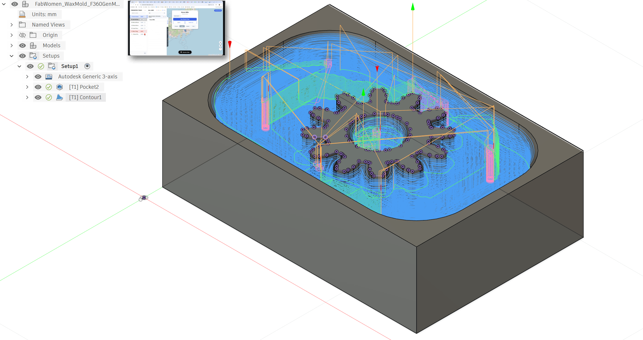
STEP 1 — Simulate first (don't skip this) In the Manufacturing workspace, right click your operations in the browser tree → Simulate. Watch the material removal animation and confirm: - No crashes - Cuts are going where expected - Z doesn't do anything weird Hit Stop when satisfied.
STEP 2 — Select operations to post In the browser tree on the left, click SETUP1 to select all operations at once. Both POCKET2 and CONTOUR1 will be highlighted. This posts them together as one G-code file in the correct order.
STEP 3 — Open Post Process In the top toolbar → Actions → Post Process Or right click SETUP1 → Post Process
STEP 4 — Select the GRBL post processor In the Post Process dialog: - Click the dropdown next to Post - Click the small library icon to open post library - Search grbl - Select Autodesk / grbl / grbl - Click Select
STEP 5 — Set output options - Program name/number — give it a simple name like "beeswax_gear" - Output folder — pick somewhere easy to find like your Desktop - Open in editor — optionally check this to preview the G-code - Leave everything else default
STEP 6 — Hit Post Click Post button. Fusion generates a .nc file on your Desktop.
STEP 7 — Open Candle Download from: github.com/Denvi/Candle if you don't have it. Open Candle and connect to your 3018: - Select correct COM port from dropdown - Baud rate 115200 - Click Open - You should see GRBL version text in the console — confirms connection
STEP 8 — Load your G-code File → Open → navigate to your .nc file on the Desktop → Open You'll see the toolpath render in the Candle viewport. Confirm it looks like your gear shape from the top.
STEP 9 — Secure your beeswax Clamp your beeswax block to the spoilboard. Options: - Double sided tape (works well for wax — clean and simple) - Small clamps at corners Make sure it won't shift — wax is light and cutting forces can move it.
STEP 10 — Zero your machine This is the most critical step — must match your Fusion WCS setup exactly.
- Jog to the top-left-front corner of your beeswax block (matching your Stock Box Point selection in Fusion)
- Lower Z until tool just touches the top surface — paper method or just barely touching
- In Candle click Zero X, Zero Y, Zero Z
- All three coordinates should show 0.000
STEP 11 — Do a dry run (air cut) Before cutting wax: 1. Raise Z by 5–10mm above your zero 2. Re-zero only Z at that raised position 3. Hit Run — watch the machine trace the toolpath in air 4. Confirm no crashes, correct XY movement, no limit switch triggers 5. Re-zero Z back at the actual material surface when satisfied
STEP 12 — Run the job 1. Confirm Z is zeroed at material surface 2. Spindle starts automatically from G-code (M3 command) 3. Hit Send in Candle 4. Watch the first few passes closely 5. Keep your hand near the Feed Hold button (pause) and Reset (emergency stop) in Candle
STEP 13 — Watch for beeswax-specific issues - Wax gumming on bit — pause and clear with a brush if you see buildup - Melting/smearing — increase feedrate using the feed override slider in Candle - Chatter/vibration — reduce feedrate
STEP 14 — Job complete When done the spindle stops (M5 command) and machine parks. Don't touch the part until the spindle fully stops. Clear wax chips with a brush — not compressed air directly on hot wax or it can splatter.
Key files you need: - Fusion 360 with GRBL post processor - Candle (github.com/Denvi/Candle) — free and open source - Your .nc file on Desktop
Working in Candle
After homing and then pressing run.. the tool dragged across the part to the center and then rose up and started to drill in the air.
The fix was two things working together:
Problem 1 — Heights were too low The retract and clearance heights were set so low that Fusion threw a warning — "Lifting retract height to safe height / Lifting clearance height to retract height" — and was overriding them internally, creating unpredictable first moves.
Fix: Increased both Retract Height and Clearance Height offsets to 4mm on the Heights tab -
NOTE: this stopped the erroring out because we couldnt go any higher.. there isnt much z access on the genmitsu.
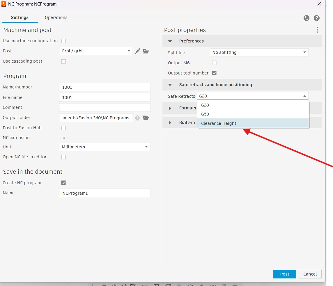
Problem 2 — G28 safe retract setting The post processor was set to G28 which sends the machine to its hardware home position between moves. After homing, the machine moved XY to the first cut position while Z was still at or near material surface — dragging the tool across the wax.
Fix: Changed the Safe Retracts setting in the Post Process dialog from G28 to Clearance Height — this forces Z to lift to your defined clearance height before any XY movement happens.
In short:
Tool was moving XY before lifting Z on the first move. Fixed by raising retract heights so Fusion stopped overriding them, and changing Safe Retracts from G28 to Clearance Height so Z always lifts before XY moves.