
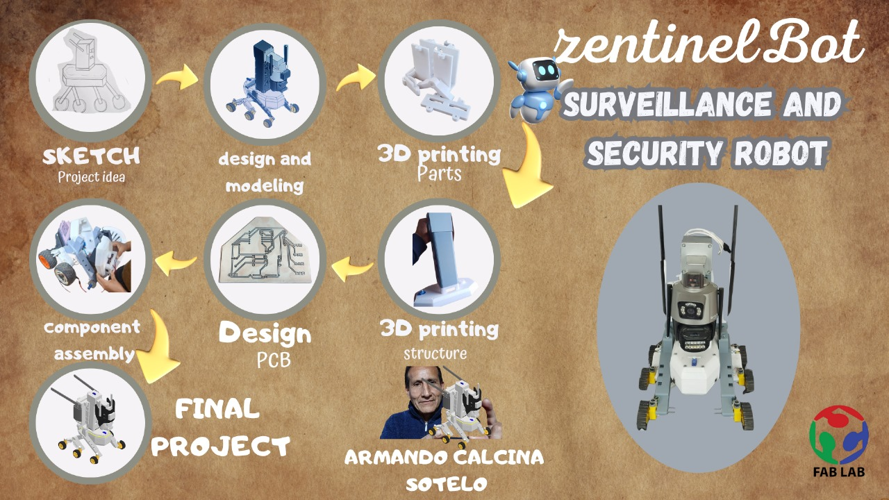
ZentinelBot
Have you answered these questions?
- Made your slide > 1920 x 1080 pixels with your name, project name, Fab Lab name, a photo/render/sketch of your project, a brief description of what your project is/does ✅
- Made a ~1 minute (25MB/1080p) video of you explaining your project ✅
- Made a separate Final Project page that summarises/documents your project ✅
- Included the BOM (Bill of Materials) for your project ✅
- Linked from this page to any weeks that you worked on your final project ✅
- Documented how you implemented system integration in your final project ✅
- Linked to your presentation.png and presentation.mp4; make sure they are located to the root of your website ✅
- Included all of your original design files in the archive (2D & 3D, board files & code). No external hosting of final project files - discuss file sizes with your instructor ✅
- Included the license you chose ✅
- Acknowledged work done by others ✅
About my project ZentinelBot: a surveillance and security robot
What will it do?
The robot will autonomously perform surveillance tasks, such as patrolling an area, detecting suspicious movements or sounds, capturing images or video, and sending real-time alerts. It will be designed to operate indoors in factories, warehouses, or homes, helping to improve environmental security.
Its main functions include:
- Patrolling industrial, commercial, or home environments
- Obstacle avoidance using ultrasonic sensors
- Remote monitoring through a web or mobile interface
- Capturing evidence (photos/videos) during unusual events
- Sending alerts instantly to the user when detecting a threat
Who’s done what beforehand?
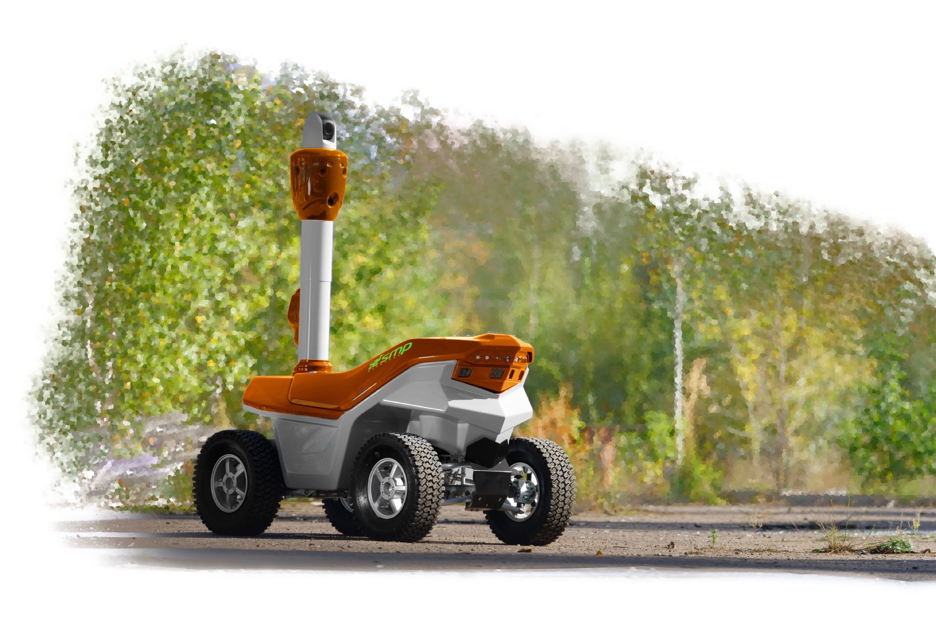
While this type of robot already exists, SMP Robotics is an American company, a leader in the development of autonomous security solutions, specializing in the manufacture of outdoor surveillance robots. Based in Sausalito, California, SMP Robotics has distinguished itself by integrating advanced artificial intelligence, computer vision, and autonomous navigation technologies into its security systems.
What will you design?
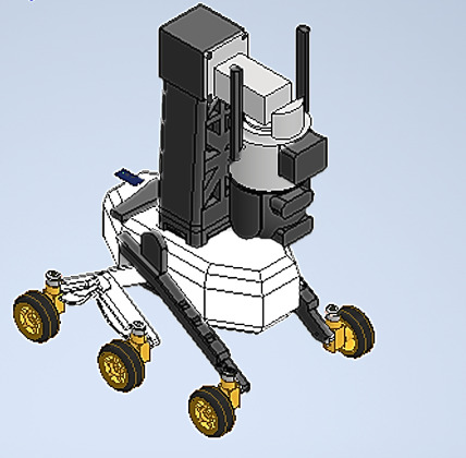
My goal is to design a robot that moves around an environment, performing surveillance and security tasks. It is based on generative design techniques for a robotic structure inspired by the skeleton of an armadillo, which will allow for a significant reduction in the volume and weight of mechanical components compared to traditional designs.
It contains a system controlled by a XIAO ESP 32-C3 microcontroller, fixed to a PCB design. It will perform real-time control and monitoring functions, using sensors and cameras to detect images in dangerous situations and send the information to the user.
What materials and components will be used?
Where did they come from?
How much did they cost?
The mechanical structure of the head, chassis, and supports will be 3D printed using PLA filament. A PCB board and various electronic devices will be used for the electronics. A PS4 12V battery will be used for the power component, along with cameras and sensors. Six wheels and six motors will be used for the movement.
It contains a system controlled by a XIAO ESP 32-C3 microcontroller, fixed to a PCB design. It will perform real-time control and monitoring functions, using sensors and cameras to detect images in dangerous situations and send the information to the user.
| Component | Description / Use | Source | Unit Cost (USD) | Quantity | Total Cost (USD) |
|---|---|---|---|---|---|
| XIAO ESP32-C3 | Main microcontroller | Electro Store | $9.00 | 1 | $9.00 |
| ROB-14450 | Voltage Regulator Module | Online Supplier | $6.50 | 1 | $6.50 |
| L7805CV | 5V Voltage Regulator | Electronics Store | $0.40 | 1 | $0.40 |
| 12V Battery (3Ah) | Main Power Supply | Hardware Store | $15.80 | 1 | $15.80 |
| Polarized Capacitor | Power Stabilization | Electronics Store | $0.90 | 1 | $0.90 |
| Ultrasonic Sensor HC-SR04 | Obstacle Detection | Saisac Electronics | $4.00 | 1 | $4.00 |
| Servomotor SG90 | Rotation Mechanism | Bora Electronics | $3.20 | 1 | $3.20 |
| WS2812B LED | Lighting Effects | Saisac Electronics | $10.50 | 1 | $10.50 |
| 12V Gear Motor (x6) | Main Drive Motors | Supplier XYZ | $3.20 | 6 | $19.20 |
| Wheel 84mm (x6) | Mobility Wheels | 3D Print Shop | $4.00 | 6 | $24.00 |
| PLA Filament (1kg) | 3D Printed Body | Garage Lab | $22.40 | 1 | $22.40 |
| Dual-Lens IP Camera | Video Capture | Online Supplier | $79.00 | 1 | $79.00 |
| Total Project Cost (USD): | $194.90 | ||||
What parts and systems will be made?
The entire structure of the robot, which consists of the head, chassis, supports, and links, will be manufactured and printed in 3D. For the electronic part, I will manufacture the PCB boards myself using the CNC PCB.
What processes were used?
- 3D Printing
- PCB Machining
- Electronic Design
- Electronic Production
- Input/Output and Programming
What questions need to be answered?
- What is the robot's main purpose?
- What problems does it solve?
- What are the main components and their functions?
- How does the robot detect intruders or anomalies?
What worked? What didn’t?
So far, the robot's movements and displacements have worked, as well as communication via Wi-Fi. Now, it needs better movement in the spaces to carry out surveillance and monitoring of the information.
How was it evaluated?
Our Robot will be evaluated when it fulfills the programmed functions and operations of providing surveillance and security.
What are the implications?
Implications of the Robot Design
Technical Implications
The use of an ultrasonic sensor allows the robot to detect obstacles at short distances, improving autonomous navigation in structured environments. The dual-lens IP camera offers a wide and detailed view, ideal for surveillance, but requires a stable network connection and reliable power supply. An efficient power management system is necessary, and compatibility between electronic modules must be ensured.
Social Implications
Since the robot is designed to operate in shared or private spaces, it may raise concerns about constant surveillance. It is important that its use is transparent to people in the area, ensuring that privacy is not violated without consent or notification. Its presence should feel safe rather than intrusive.
Ethical Implications
The inclusion of a camera enables image capture of people and environments. Therefore, unnecessary data storage must be avoided, and limits on automatic recording should be implemented. All critical decisions must remain under human supervision to ensure accountability and fairness.
Environmental Implications
The robot body is made of 3D-printed parts optimized to reduce plastic usage. Rechargeable batteries were chosen to minimize electronic waste. The modular design allows for individual part replacement without discarding the entire system, supporting repairability and sustainability.
Concept
ZentinelBot is my robot designed to help keep spaces safe. It combines an ultrasonic sensor that allows it to “sense” nearby obstacles and a dual-lens IP camera that monitors everything in real time.
The idea is for ZentinelBot to patrol autonomously, avoiding collisions and sending images or alerts when it detects something unusual. Additionally, you can monitor and control it from your phone or computer, making it easy to stay aware even from a distance.
This project aims to create a practical, accessible, and modular solution that improves security without complications, designed for homes, offices, or any place needing constant surveillance.
Project Phases
| Phase | Start Date | End Date | Progress |
|---|---|---|---|
| 1. Concept and Design | Jan 30 | May 15 | 100% |
| 2. Computer-Controlled Cutting | May 19 | May 20 | 100% |
| 3. 3D Printing | May 1 | May 10 | 100% |
| 4. Electronics Design | Feb 26 | March 5 | 100% |
| 5. Electronics Production | Marh 14 | May 10 | 100% |
| 6. Embedded Programming | Feb 15 | May 8 | 100% |
| 7. Computer-Controlled Machining | May 16 | May 21 | 100% |
| 8. Input Devices | Marh 23 | April 20 | 100% |
| 9. Output Devices | Marh 29 | April 27 | 100% |
| 10. System Integration | May 10 | May 30 | 100% |
| 11. Final Testing and Documentation | May 15 | June 04 | 100% |
Design Process and Manufacturing
Concept and Design
Concept sketch / inspiration for ZentinelBot
The idea for ZentinelBot was born from the need to improve surveillance and security using autonomous technology. Inspired by modern security systems and robotics, this robot is designed to patrol, monitor, and detect activity in real-time using sensors and a dual-lens IP camera. It aims to provide a reliable, mobile, and intelligent solution for monitoring spaces such as homes, workshops, or campuses.
This concept directly addresses the growing problem of insecurity in Peru, where crime and theft have become a major concern for both citizens and businesses. Due to resource constraints and the challenges faced by traditional security methods, many areas remain vulnerable to theft and unauthorized access. By implementing advanced robotic surveillance systems like ZentinelBot, it is possible to improve security measures, reduce human risk, and ensure continuous monitoring in vulnerable areas, thus contributing to a safer environment for communities.
1. - Sketches and Schedule
Initially, I created a sketch of my robot based on the structure of an armadillo's skeleton, focusing mainly on the body. The design incorporates antennae that are part of the IP camera system, which serve as the robot’s sensory input. The head of the robot is the IP camera itself, equipped with dual lenses for enhanced surveillance capabilities. Additionally, the robot is equipped with ultrasonic sensors to measure distances and detect obstacles.
This biological inspiration guided the overall mechanical design, aiming to achieve a robust and flexible structure suitable for surveillance and security tasks. The armadillo’s natural armor inspired the protective casing, providing durability and resistance to external impacts. By mimicking its skeletal framework, I intended to combine strength with mobility, allowing the robot to navigate different terrains while maintaining structural integrity.
This concept forms the foundation of ZentinelBot, a security robot designed to improve monitoring and safety through advanced sensing technologies.
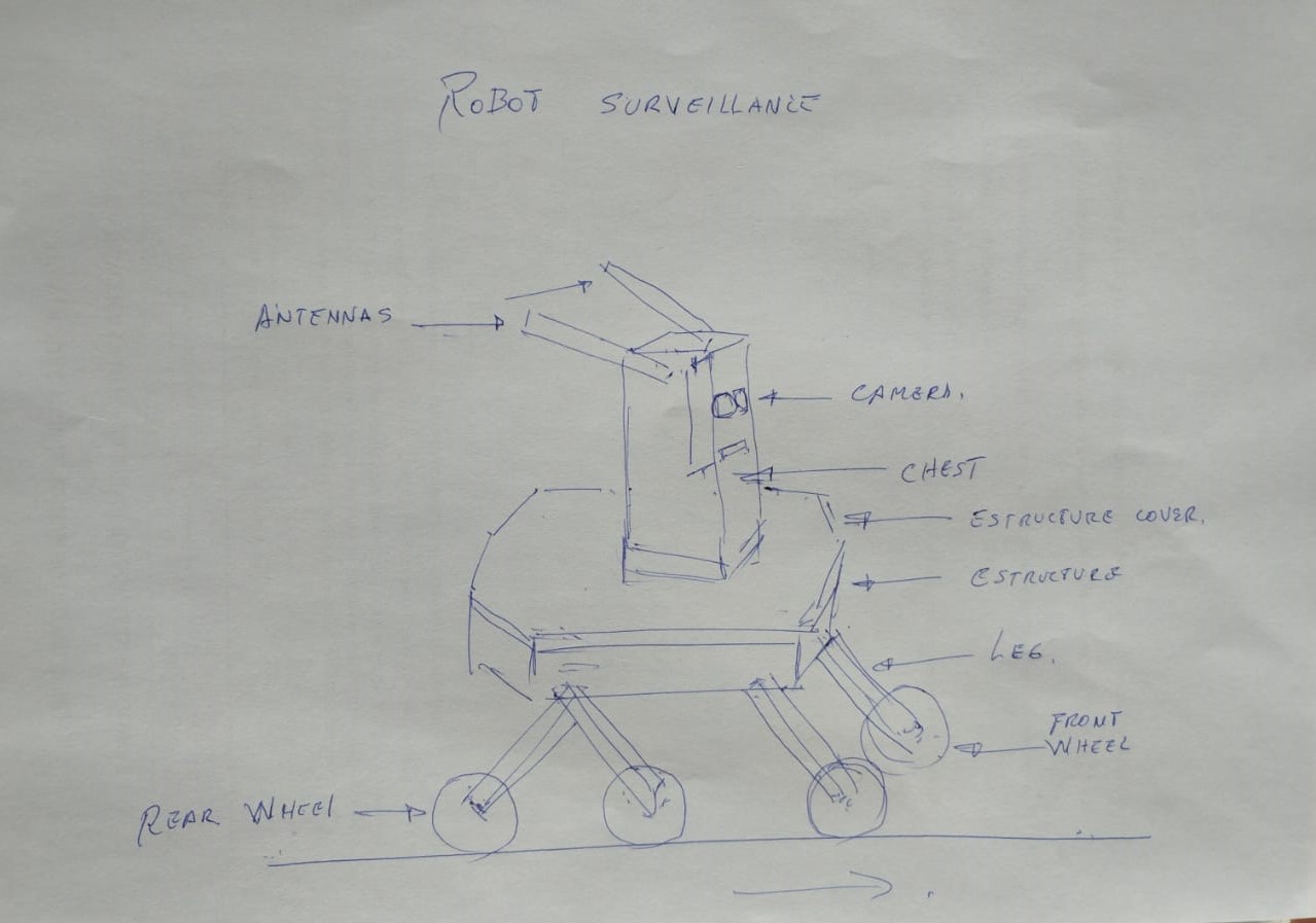
Initial sketch of my robot
GANTT CHART
During the various assignments, I was able to learn and improve my designs using different CAD programs. For example, in week 2, I worked with SolidWorks and Inventor, creating several part designs. The structural design of my robot was developed in Inventor, where I also applied generative design techniques to optimize the structure and reduce weight.
Structural Design
The robot's design includes the main structure, the body, and various parts such as the limbs, as well as the support for the antennas and sensors. The structural frame serves as the base, providing stability and support for all the components.
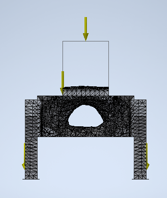
The robot's structure was created using generative design techniques. This approach allowed me to optimize the structure by automatically exploring multiple design alternatives, focusing on reducing weight while maintaining strength and durability. Thanks to generative design, the final structure is efficient and robust, providing a solid foundation for the rest of the robot's components.
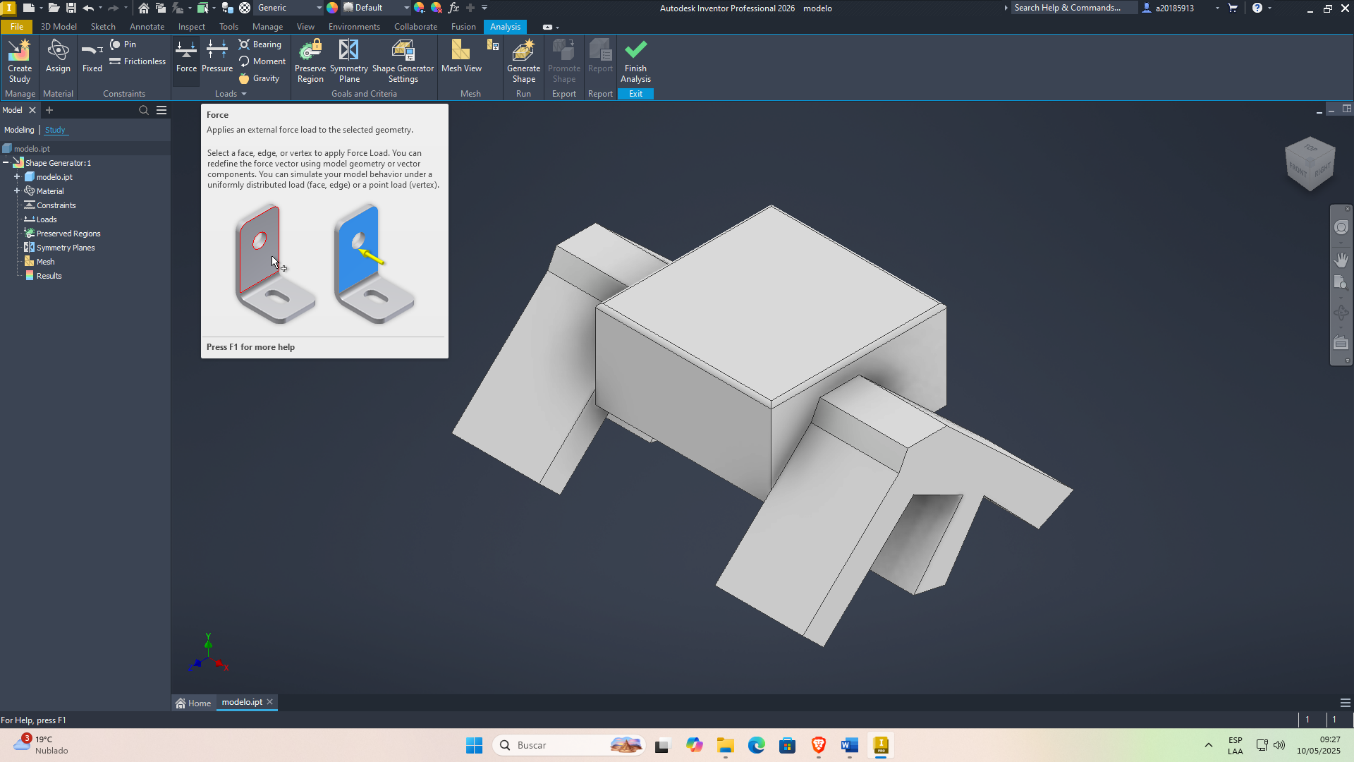
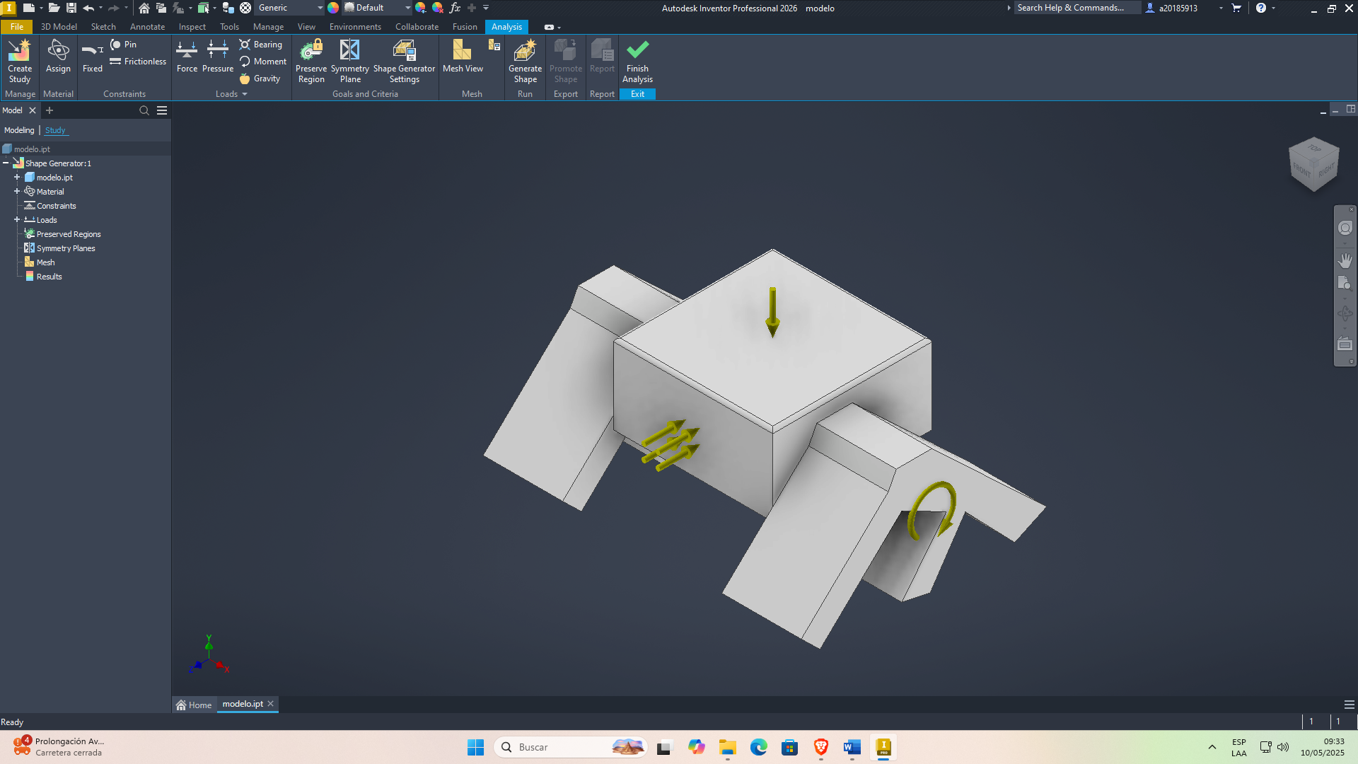
Once the working parameters have been set, we will proceed to load the generative design calculation:
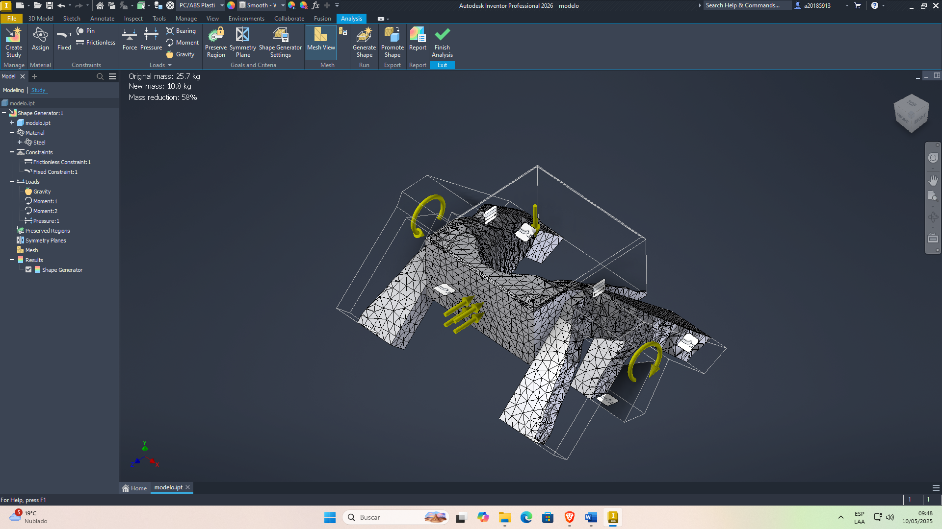
obtaining the preliminary model
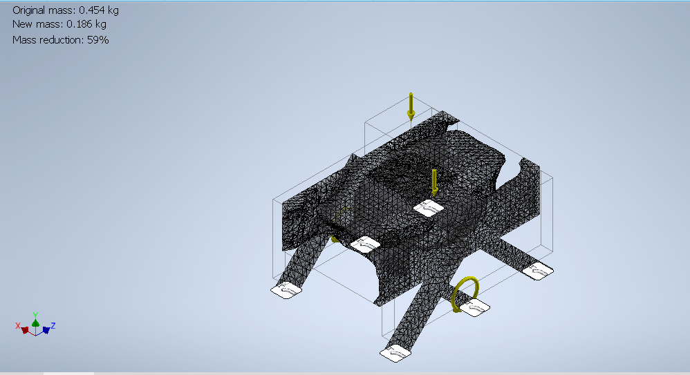
First generative isometric chassis design.
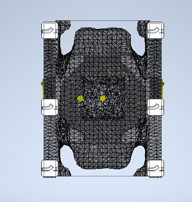
First generative design, chassis plan view.
First generative design, bottom view of the chassis.
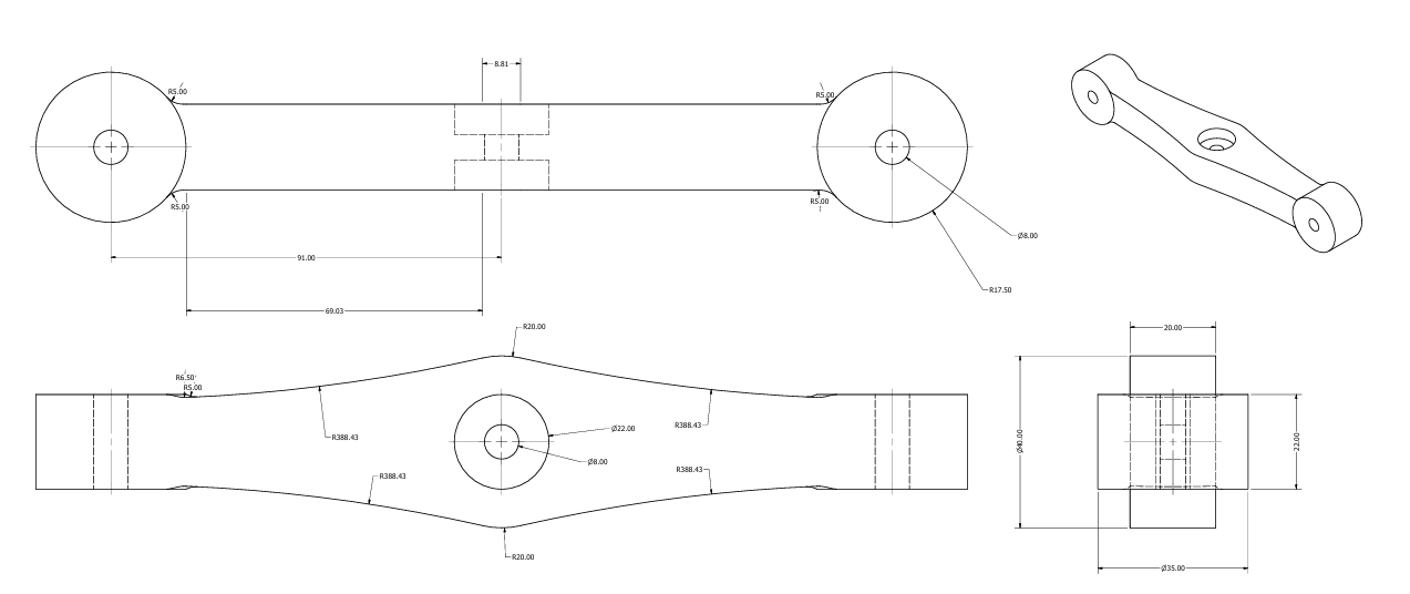
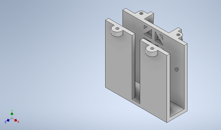
Parts Design
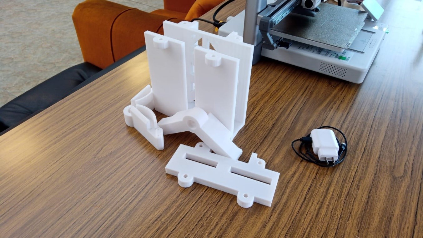
Piece 1: unions
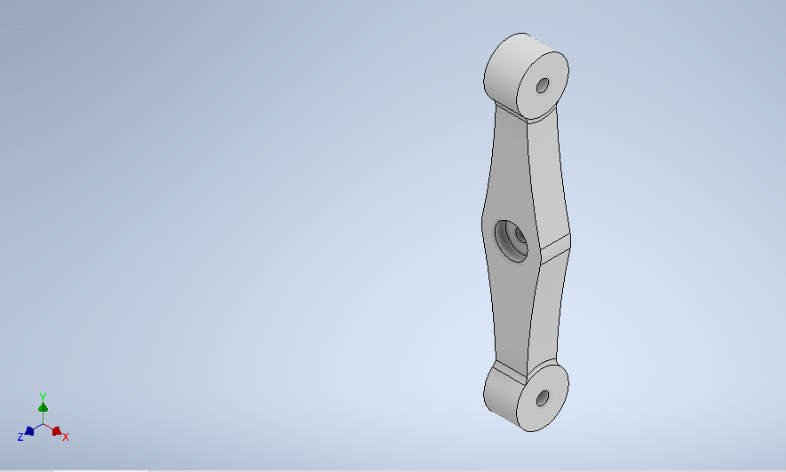
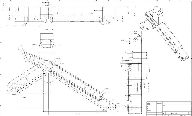
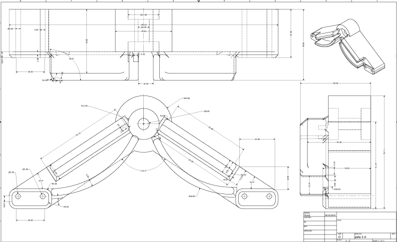
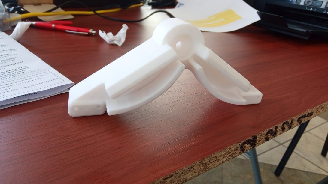
Piece 2: first leg
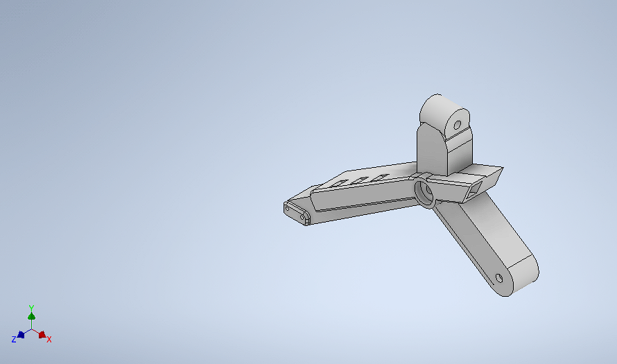
Piece 3: Second leg
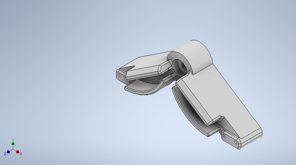
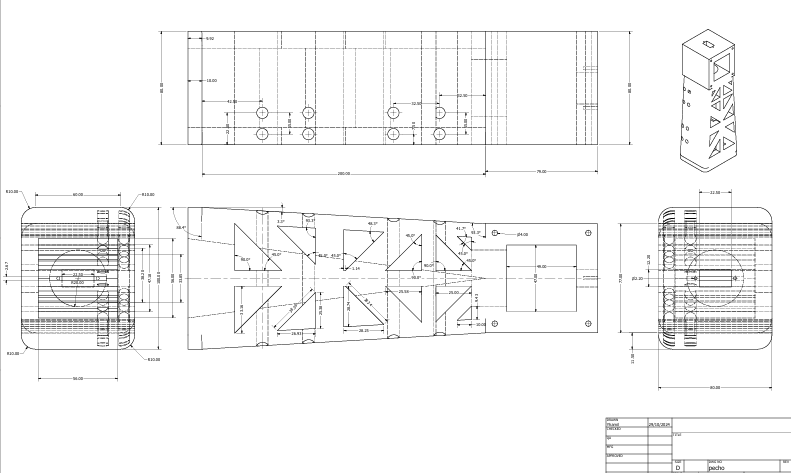
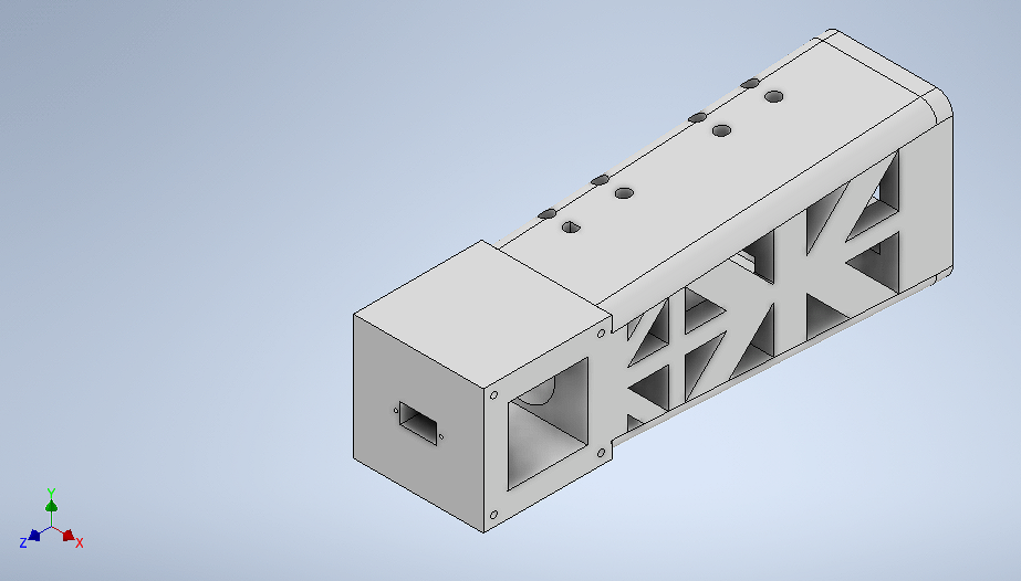
Piece 4: Chest design
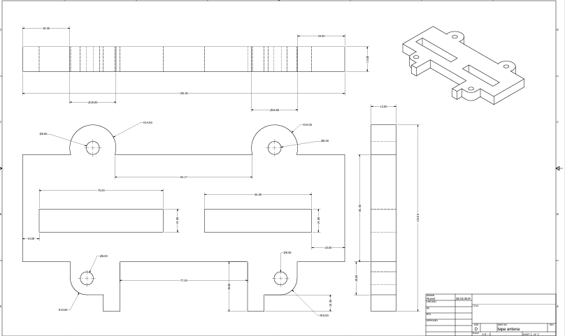
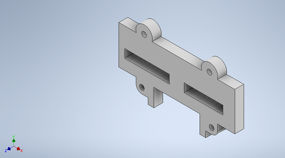
Piece 5: Antenna cover
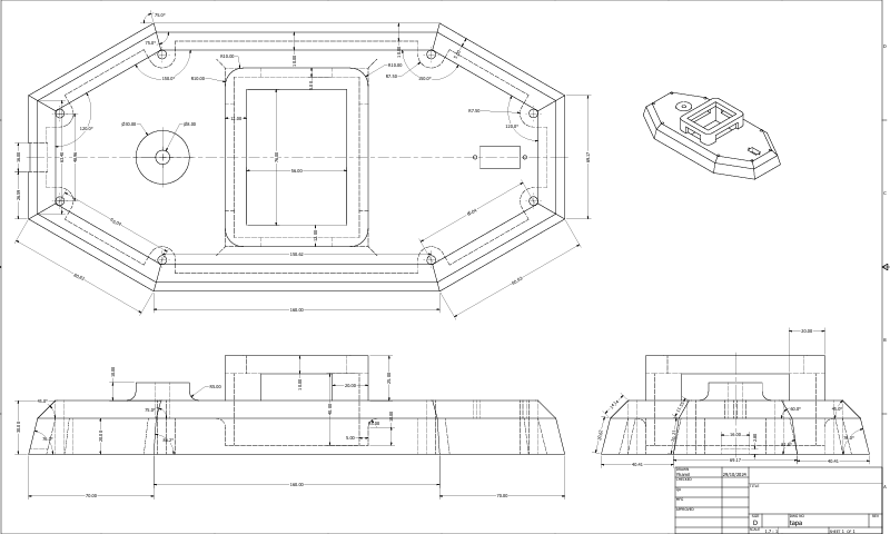
Piece 6: Cover
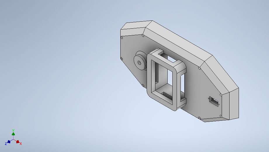
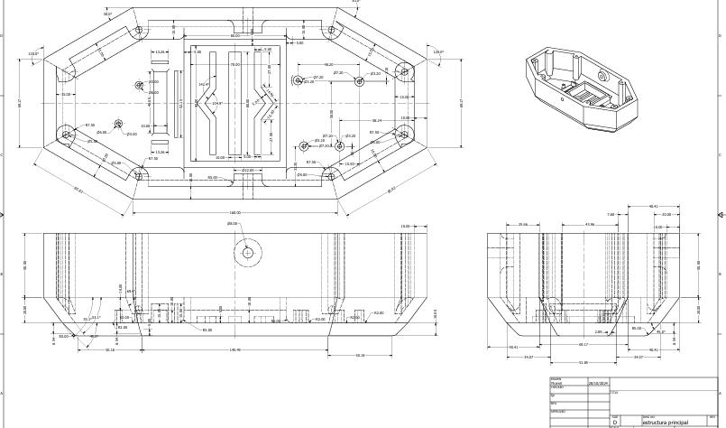
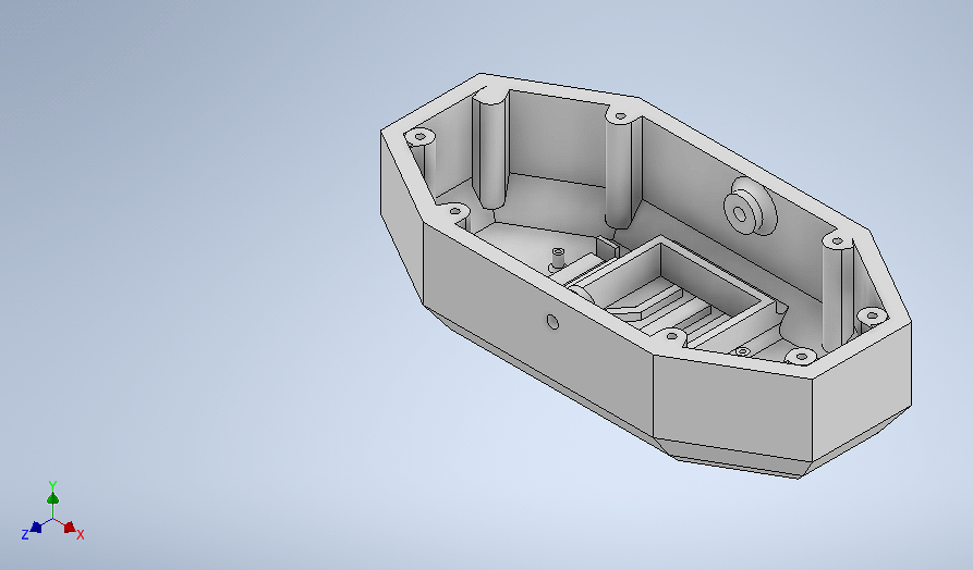
Piece 7: Main structure
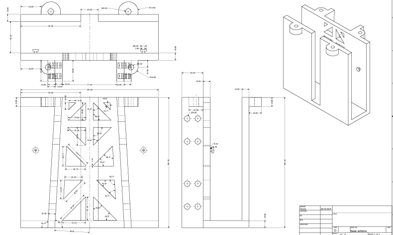
Piece 8: Antenna base
final design of the ZentinelBot robot
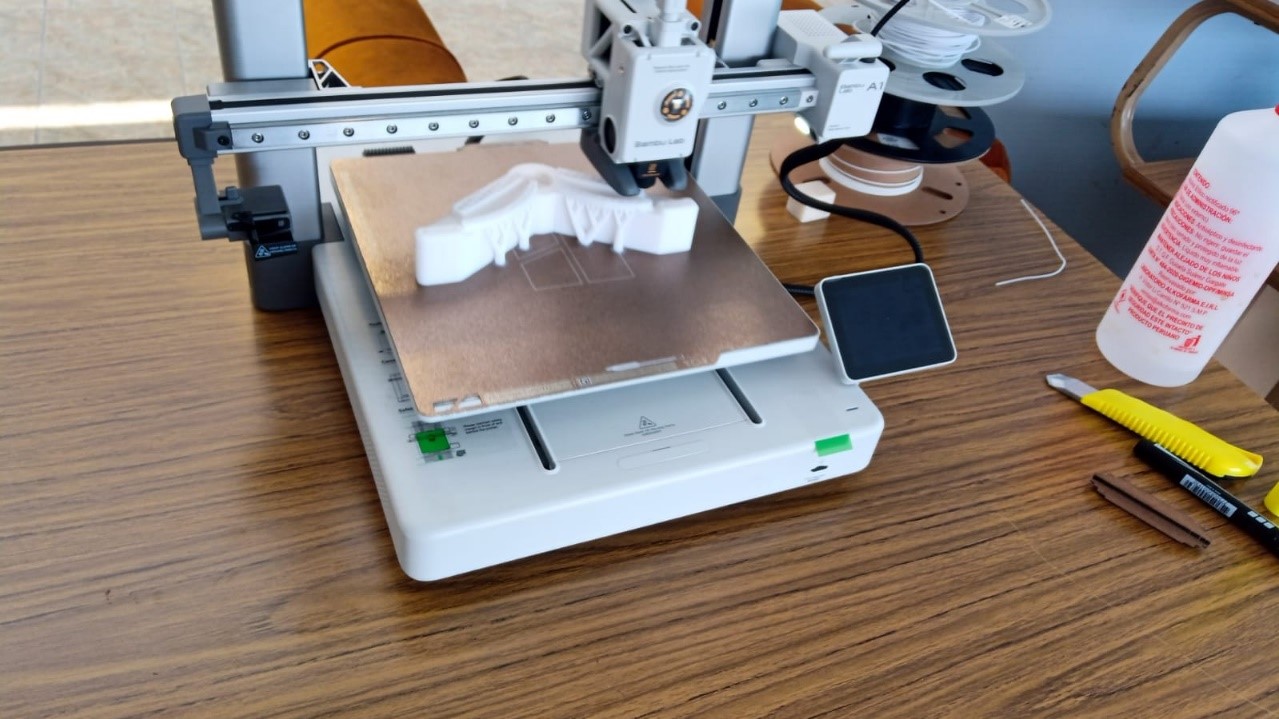
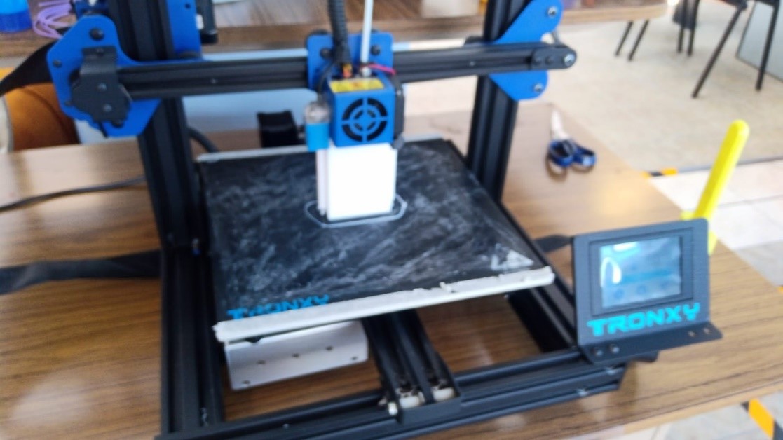
2.- 3D printing of parts
For printing the parts, we have exported the generated files in STL format. For printing small parts, the Bambu Lab printer was used, and for larger parts, the Proxy printer was used.
3.-Electronic Design
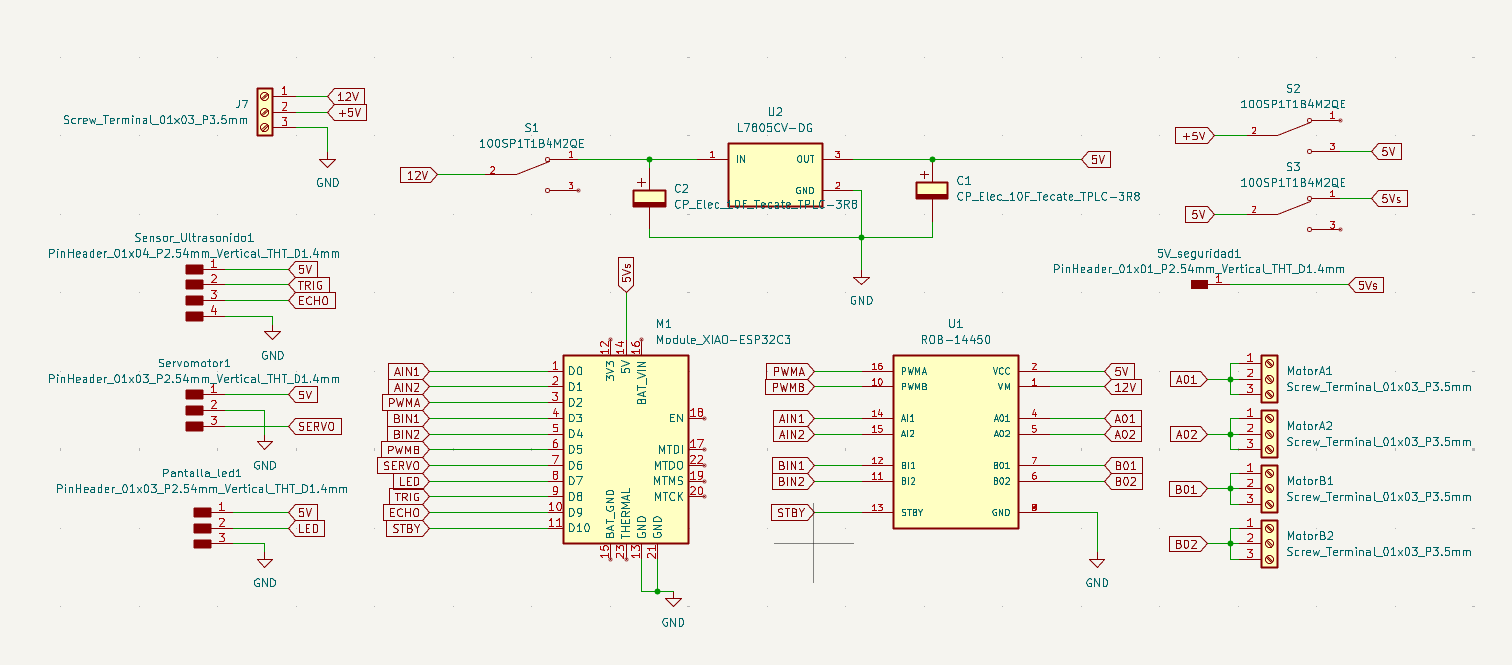
During week 6, we learned how to carry out electronic design, taking into account many aspects, such as design rules, electrical requirements such as voltages, currents and frequencies. I had certain knowledge, but with this week's development I reinforced it, making the design of my own board for my robot. To see more details of the electronic design, click here.
To perform electronic integration, we must make a list of the components we will use for the project:
- XIAO ESP32-C3
- ROB-14450 – Motor driver
- L7805CV – Voltage regulator
- Polarized capacitor
- Ultrasonic sensor
- Servomotor
- WS2812B LED strip
3.1 schematic diagram
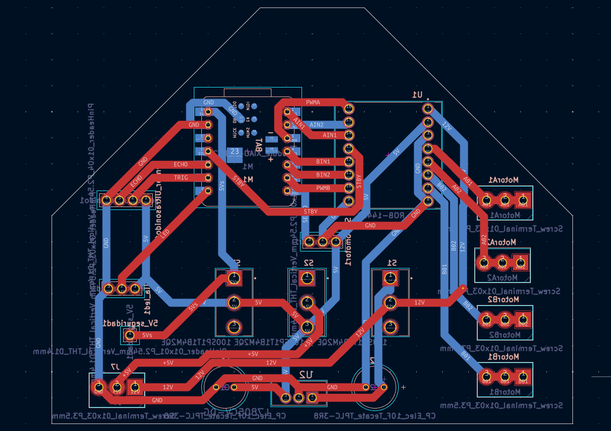
3.2 PCB layout design
3.2 3D visualization
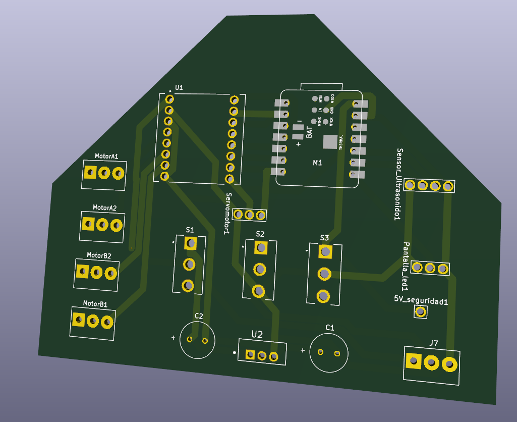
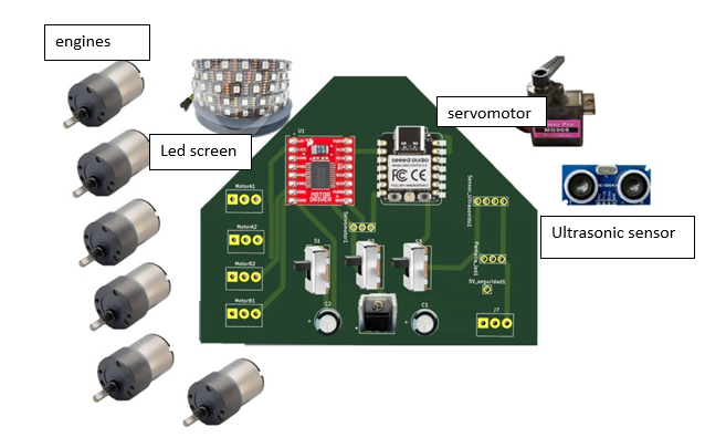
3.3 Component layout
4.-Electronic Production
During week 8, the assigned task was to manufacture the PCB based on the previously prepared electronic design. To do this, I used a CNC milling machine specialized in printed circuit board manufacturing, which allowed me to perform precise engraving and drilling. Tools such as milling cutters of different sizes were used to remove unwanted copper and create the circuit traces. In addition, parameters such as machine speed, cutting depth, and board cleanliness were taken into account to ensure an optimal and functional finish. Finally, the circuit's continuity and proper operation were verified before its integration into the project.
For more details you can see here Electronic production
.jpeg)
.jpeg)
5.-Embedded Programming
During week 4, we completed embedded programming, using the Arduino IDE development environment. In this stage, we wrote the initial codes to control the robot's sensors and actuators, such as the ultrasonic sensor, motors, and camera. The microcontroller's digital inputs and outputs were configured, the basic operating logic was established, and read and response tests were performed. This programming was essential for validating the expected behavior of the electronic components and laying the groundwork for the robot's autonomous control.
.jpeg)
.jpeg)
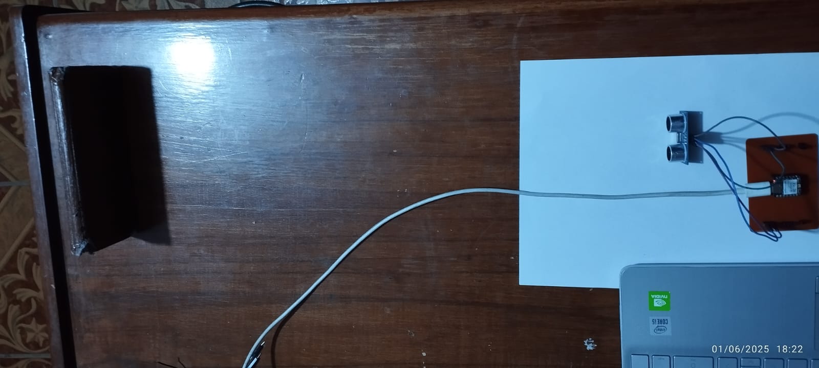
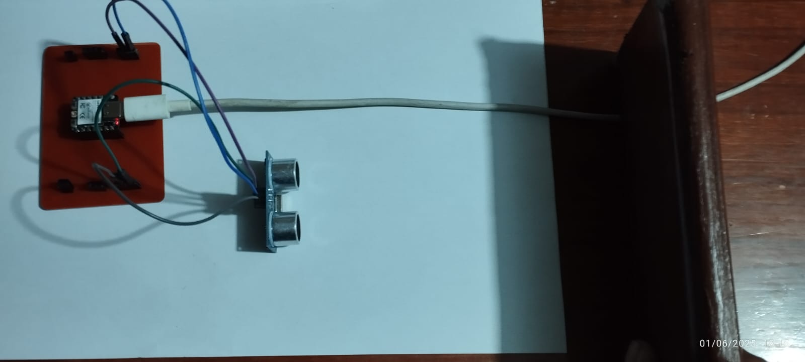
6.- Input Devices
In the robot's design, the primary input device used was the HC-SR04 ultrasonic sensor, which measures distances using sound waves. This sensor works by emitting an ultrasonic pulse from the Trigger pin and waiting for the reflected echo received on the Echo pin. The time it takes for the echo to return is used to calculate the distance to the object. During the testing phase, the sensor was connected to the ESP32-C3 microcontroller and programmed to detect obstacles in front of the robot. This information was essential for allowing the robot to react to the presence of objects, stopping or changing direction.
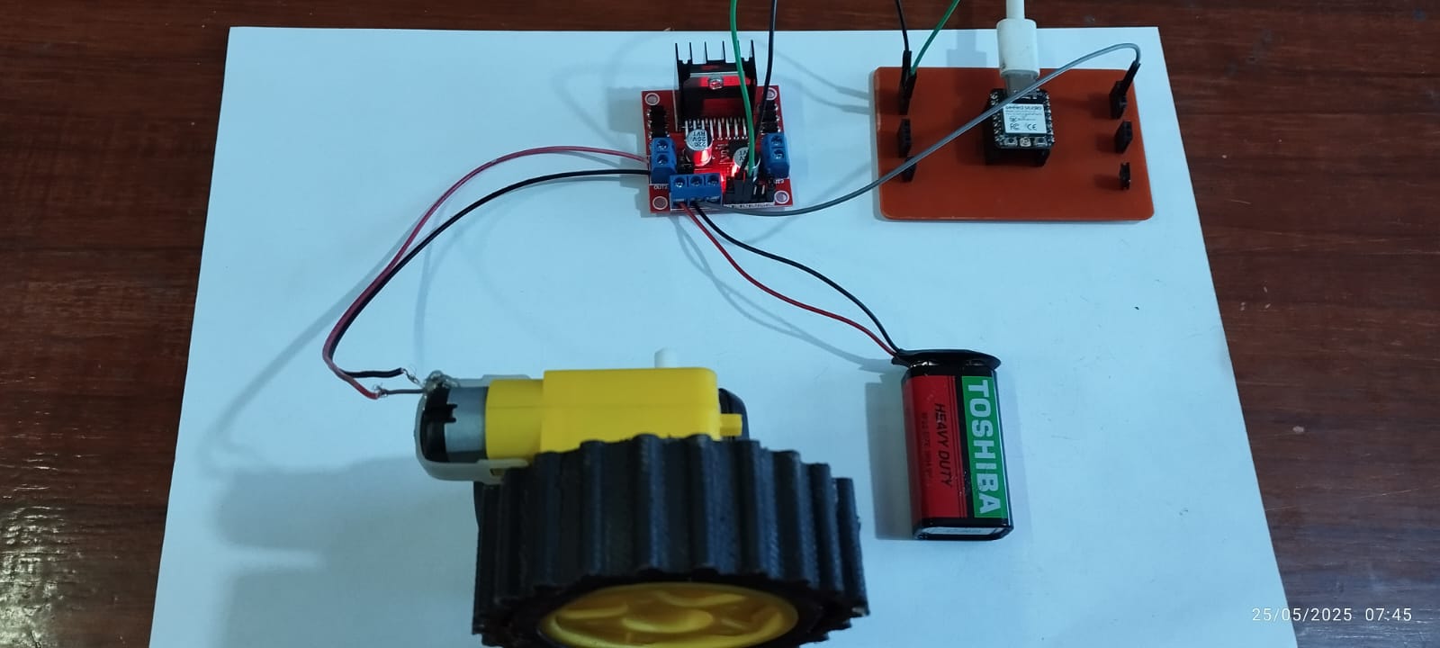
7.- Output Devices
During the initial tests and assigned tasks, we initially worked with a single DC motor coupled to a wheel as a load. This stage was essential for validating the motor's basic control and understanding output behavior under realistic weight and friction conditions.
8.-Electronic Programming
This code configures the ESP32-C3 XIAO microcontroller as a WiFi web server, allowing the robot to be controlled from a web browser over a local network. The user can access a graphical interface with buttons (forward, backward, left, right, stop) that, when pressed, send commands to the ESP32-C3 to activate the robot's motors.
#include <WiFi.h>
#include <WebServer.h>
#include <ESP32Servo.h>
#include <Adafruit_NeoPixel.h>

// Configuración WiFi
const char* ssid = "ESP_AP";
const char* password = "123456789";

// Definición de pines
#define STBY_PIN   10
#define AIN1_PIN   2
#define AIN2_PIN   3
#define PWMA_PIN   4
#define BIN1_PIN   5
#define BIN2_PIN   6
#define PWMB_PIN   7
#define TRIG_PIN   8
#define ECHO_PIN   9
#define SERVO_PIN  21
#define LED_PIN    20  // GPIO para la tira LED
#define LED_COUNT  96  // Número de LEDs en tu matriz

WebServer server(80);
Servo obstacleServo;
Adafruit_NeoPixel strip(LED_COUNT, LED_PIN, NEO_GRB + NEO_KHZ800);

// Variables para el modo autónomo
bool autonomousMode = false;
String currentDirection = "stop";
const int motorSpeed = 255;
const float safeDistance = 30.0;

// Configuración del servo
const int servoMinAngle = -45;
const int servoMaxAngle = 45;
const int servoCenter = 0;
int currentServoAngle = servoCenter;
bool servoMoving = false;
unsigned long lastServoMove = 0;
const int servoMoveInterval = 100;
int servoDelay = 40;

// Sensor ultrasónico
unsigned long lastPingTime = 0;
const int pingInterval = 100;
float currentDistances[3] = {0, 0, 0};
bool waitingForEcho = false;
unsigned long echoStartTime = 0;

// Estados
enum State { SCANNING, PROCESSING, MOVING };
State currentState = SCANNING;
unsigned long stateStartTime = 0;

// Red neuronal
const int InputNodes = 3;
const int HiddenNodes = 4;
const int OutputNodes = 4;
double Hidden[HiddenNodes];
double Output[OutputNodes];

float HiddenWeights[3][4] = {
    {1.8991509504079183, -0.4769472541445052, -0.6483690220539764, -0.38609165249078925},
    {-0.2818610915467527, 4.040695699457223, 3.2291858058243843, -2.894301104732614},
    {0.3340650864625773, -1.4016114422346901, 1.3580053902963762, -0.981415976256285}
};

float OutputWeights[4][4] = {
    {1.136072297461121, 1.54602394937381, 1.6194612259569254, 1.8819066696635067},
    {-1.546966506764457, 1.3951930739494225, 0.19393826092602756, 0.30992504138547006},
    {-0.7755982417649826, 0.9390808625728915, 2.0862510744685485, -1.1229484266101883},
    {-1.2357090352280826, 0.8583930286034466, 0.724702079881947, 0.9762852709700459}
};

// Image matrices for the LED strip (FILL THEM WITH YOUR VALUES!)
uint32_t frameForward[LED_COUNT] = {
  0xFFFFFF, 0x000000, 0x000000, 0x000000, 0x000000, 0x000000, 0x000000, 0x000000, 0x000000, 0x000000, 0x000000, 0xFFFFFF,
  0x000000, 0x0000FF, 0x000000, 0x000000, 0x000000, 0x000000, 0x000000, 0x000000, 0x000000, 0x000000, 0x0000FF, 0x000000,
  0x000000, 0x00FF00, 0x0000FF, 0x000000, 0x000000, 0x000000, 0x000000, 0x000000, 0x000000, 0x0000FF, 0x00FF00, 0x000000,
  0x000000, 0x00FF00, 0xFF0000, 0x0000FF, 0x000000, 0x000000, 0x000000, 0x000000, 0x0000FF, 0xFF0000, 0x00FF00, 0x000000,
  0x000000, 0x000000, 0x00FF00, 0x00FF00, 0x000000, 0x007FFF, 0x007FFF, 0x000000, 0x00FF00, 0x00FF00, 0x00FF00, 0x000000,
  0x000000, 0x000000, 0x000000, 0x000000, 0x000000, 0x000000, 0x000000, 0x000000, 0x000000, 0x000000, 0x000000, 0x000000,
  0xFFFFFF, 0xFFFFFF, 0x000000, 0x000000, 0xFFFF00, 0xFFFF00, 0xFFFF00, 0xFFFF00, 0x000000, 0x000000, 0xFFFFFF, 0xFFFFFF,
  0xFFFFFF, 0xFFFFFF, 0x000000, 0xFFFF00, 0x000000, 0x000000, 0x000000, 0x000000, 0xFFFF00, 0x000000, 0xFFFFFF, 0xFFFFFF
};

uint32_t frameBackward[LED_COUNT] = {
  0xFFFFFF, 0x000000, 0x000000, 0x000000, 0x000000, 0x000000, 0x000000, 0x000000, 0x000000, 0x000000, 0x000000, 0xFFFFFF,
  0x000000, 0x0000FF, 0x0000FF, 0x0000FF, 0x000000, 0x000000, 0x000000, 0x000000, 0x0000FF, 0x0000FF, 0x0000FF, 0x000000,
  0x000000, 0x00FF00, 0xFF0000, 0x00FF00, 0x000000, 0x000000, 0x000000, 0x000000, 0x00FF00, 0xFF0000, 0x00FF00, 0x000000,
  0x000000, 0x00FF00, 0xFF0000, 0x00FF00, 0x000000, 0x007FFF, 0x007FFF, 0x000000, 0x00FF00, 0xFF0000, 0x00FF00, 0x000000,
  0x000000, 0x00FF00, 0x00FF00, 0x00FF00, 0x000000, 0x007FFF, 0x007FFF, 0x000000, 0x00FF00, 0x00FF00, 0x00FF00, 0x000000,
  0x000000, 0x000000, 0x000000, 0x000000, 0x000000, 0x000000, 0x000000, 0x000000, 0x000000, 0x000000, 0x000000, 0x000000,
  0xFFFFFF, 0xFFFFFF, 0x000000, 0xFFFF00, 0x000000, 0x000000, 0x000000, 0x000000, 0xFFFF00, 0x000000, 0xFFFFFF, 0xFFFFFF,
  0xFFFFFF, 0xFFFFFF, 0x000000, 0x000000, 0xFFFF00, 0xFFFF00, 0xFFFF00, 0xFFFF00, 0x000000, 0x000000, 0xFFFFFF, 0xFFFFFF
};

uint32_t frameLeft[LED_COUNT] = {
  0xFFFFFF, 0x000000, 0x000000, 0x000000, 0x000000, 0x000000, 0x000000, 0x000000, 0x000000, 0x000000, 0x000000, 0xFFFFFF,
  0x000000, 0x0000FF, 0x0000FF, 0x0000FF, 0x000000, 0x000000, 0x000000, 0x000000, 0x000000, 0x000000, 0x000000, 0x000000,
  0x000000, 0x000000, 0x000000, 0x000000, 0x000000, 0x000000, 0x000000, 0x000000, 0x00FF00, 0xFF0000, 0x00FF00, 0x000000,
  0x000000, 0x00FF00, 0xFF0000, 0x00FF00, 0x000000, 0x000000, 0x000000, 0x000000, 0x0000FF, 0x0000FF, 0x0000FF, 0x000000,
  0x000000, 0x00FF00, 0x00FF00, 0x00FF00, 0x000000, 0x007FFF, 0x007FFF, 0x000000, 0x00FF00, 0x00FF00, 0x00FF00, 0x000000,
  0x000000, 0x000000, 0x000000, 0x000000, 0x000000, 0x000000, 0x000000, 0x000000, 0x000000, 0x000000, 0x000000, 0x000000,
  0xFFFFFF, 0xFFFFFF, 0x000000, 0xFFFF00, 0x000000, 0x000000, 0x000000, 0x000000, 0xFFFF00, 0x000000, 0xFFFFFF, 0xFFFFFF,
  0xFFFFFF, 0xFFFFFF, 0x000000, 0x000000, 0xFFFF00, 0xFFFF00, 0xFFFF00, 0xFFFF00, 0x000000, 0x000000, 0xFFFFFF, 0xFFFFFF
};

uint32_t frameRight[LED_COUNT] = {
  0xFFFFFF, 0x000000, 0x000000, 0x000000, 0x000000, 0x000000, 0x000000, 0x000000, 0x000000, 0x000000, 0x000000, 0xFFFFFF,
  0x000000, 0x000000, 0x000000, 0x000000, 0x000000, 0x000000, 0x000000, 0x000000, 0x0000FF, 0x0000FF, 0x0000FF, 0x000000,
  0x000000, 0x00FF00, 0xFF0000, 0x00FF00, 0x000000, 0x000000, 0x000000, 0x000000, 0x000000, 0x000000, 0x000000, 0x000000,
  0x000000, 0x0000FF, 0x0000FF, 0x0000FF, 0x000000, 0x000000, 0x000000, 0x000000, 0x00FF00, 0xFF0000, 0x00FF00, 0x000000,
  0x000000, 0x00FF00, 0x00FF00, 0x00FF00, 0x000000, 0x007FFF, 0x007FFF, 0x000000, 0x00FF00, 0x00FF00, 0x00FF00, 0x000000,
  0x000000, 0x000000, 0x000000, 0x000000, 0x000000, 0x000000, 0x000000, 0x000000, 0x000000, 0x000000, 0x000000, 0x000000,
  0xFFFFFF, 0xFFFFFF, 0x000000, 0xFFFF00, 0x000000, 0x000000, 0x000000, 0x000000, 0xFFFF00, 0x000000, 0xFFFFFF, 0xFFFFFF,
  0xFFFFFF, 0xFFFFFF, 0x000000, 0x000000, 0xFFFF00, 0xFFFF00, 0xFFFF00, 0xFFFF00, 0x000000, 0x000000, 0xFFFFFF, 0xFFFFFF
};

uint32_t frameStop[LED_COUNT] = {
  0xFFFFFF, 0x000000, 0x000000, 0x000000, 0x000000, 0x000000, 0x000000, 0x000000, 0x000000, 0x000000, 0x000000, 0xFFFFFF,
  0x000000, 0x0000FF, 0x0000FF, 0x0000FF, 0x000000, 0x000000, 0x000000, 0x000000, 0x0000FF, 0x0000FF, 0x0000FF, 0x000000,
  0x000000, 0x00FF00, 0xFF0000, 0x00FF00, 0x000000, 0x000000, 0x000000, 0x000000, 0x00FF00, 0xFF0000, 0x00FF00, 0x000000,
  0x000000, 0x00FF00, 0xFF0000, 0x00FF00, 0x000000, 0x000000, 0x000000, 0x000000, 0x00FF00, 0xFF0000, 0x00FF00, 0x000000,
  0x000000, 0x00FF00, 0x00FF00, 0x00FF00, 0x000000, 0x007FFF, 0x007FFF, 0x000000, 0x00FF00, 0x00FF00, 0x00FF00, 0x000000,
  0x000000, 0x000000, 0x000000, 0x000000, 0x000000, 0x007FFF, 0x007FFF, 0x000000, 0x000000, 0x000000, 0x000000, 0x000000,
  0xFFFFFF, 0xFFFFFF, 0x000000, 0x000000, 0x000000, 0x000000, 0x000000, 0x000000, 0x000000, 0x000000, 0xFFFFFF, 0xFFFFFF,
  0xFFFFFF, 0xFFFFFF, 0x000000, 0x000000, 0xFFFF00, 0xFFFF00, 0xFFFF00, 0xFFFF00, 0x000000, 0x000000, 0xFFFFFF, 0xFFFFFF
};

// Función para mostrar imágenes en la tira LED
void showLEDFrame(uint32_t frame[]) {
  for(int i = 0; i < LED_COUNT; i++) {
    strip.setPixelColor(i, frame[i]);
  }
  strip.show();
}

void setup() {
  Serial.begin(115200);

  // Configuración de pines
  pinMode(STBY_PIN, OUTPUT);
  pinMode(AIN1_PIN, OUTPUT);
  pinMode(AIN2_PIN, OUTPUT);
  pinMode(PWMA_PIN, OUTPUT);
  pinMode(BIN1_PIN, OUTPUT);
  pinMode(BIN2_PIN, OUTPUT);
  pinMode(PWMB_PIN, OUTPUT);
  digitalWrite(STBY_PIN, HIGH);

  pinMode(TRIG_PIN, OUTPUT);
  pinMode(ECHO_PIN, INPUT);
  digitalWrite(TRIG_PIN, LOW);

  obstacleServo.attach(SERVO_PIN, 500, 2500);
  obstacleServo.write(servoCenter);

  // Inicializa la tira LED
  strip.begin();
  strip.setBrightness(50); // Ajusta el brillo (0-255)
  strip.show(); // Apaga todos los LEDs inicialmente

  WiFi.softAP(ssid, password);
  Serial.print("IP del Access Point: ");
  Serial.println(WiFi.softAPIP());

  // Configura rutas del servidor web
  server.on("/", handleRoot);
  server.on("/forward", []() { if(!autonomousMode) moveRobot("forward"); server.send(200, "text/plain", "OK"); });
  server.on("/backward", []() { if(!autonomousMode) moveRobot("backward"); server.send(200, "text/plain", "OK"); });
  server.on("/left", []() { if(!autonomousMode) moveRobot("left"); server.send(200, "text/plain", "OK"); });
  server.on("/right", []() { if(!autonomousMode) moveRobot("right"); server.send(200, "text/plain", "OK"); });
  server.on("/stop", []() { if(!autonomousMode) moveRobot("stop"); server.send(200, "text/plain", "OK"); });
  server.on("/autonomous", []() { autonomousMode = true; currentState = SCANNING; server.send(200, "text/plain", "OK"); });
  server.on("/manual", []() { autonomousMode = false; moveRobot("stop"); server.send(200, "text/plain", "OK"); });
  server.on("/autonomousData", handleAutonomousData);

  server.begin();
}

void loop() {
  server.handleClient();
  if(autonomousMode) autonomousRoutine();
}

void autonomousRoutine() {
  unsigned long currentTime = millis();

  switch(currentState) {
    case SCANNING:
      handleScanningState(currentTime);
      break;
    case PROCESSING:
      handleProcessingState(currentTime);
      break;
    case MOVING:
      handleMovingState(currentTime);
      break;
  }

  handleUltrasonicSensor(currentTime);
}

void handleScanningState(unsigned long currentTime) {
  static int scanStep = 0;
  const int scanAngles[3] = {servoMinAngle, servoCenter, servoMaxAngle};

  if(!servoMoving && currentTime - lastServoMove >= servoMoveInterval) {
    if(scanStep < 3) {
      currentServoAngle = scanAngles[scanStep];
      obstacleServo.write(currentServoAngle);
      servoMoving = true;
      lastServoMove = currentTime;
      servoDelay = (scanStep == 0 || scanStep == 2) ? 80 : 40;
      startPing();
    } else {
      currentState = PROCESSING;
      stateStartTime = currentTime;
      scanStep = 0;
    }
  }

  if(servoMoving && currentTime - lastServoMove >= servoDelay) {
    servoMoving = false;
    scanStep++;
  }
}

void handleProcessingState(unsigned long currentTime) {
  if(currentTime - stateStartTime >= 100) {
    processNeuralNetwork(currentDistances);
    currentState = MOVING;
    stateStartTime = currentTime;
  }
}

void handleMovingState(unsigned long currentTime) {
  if(currentTime - stateStartTime >= 300) {
    currentState = SCANNING;
    stateStartTime = currentTime;
  }
}

void handleUltrasonicSensor(unsigned long currentTime) {
  static bool waitingForEcho = false;
  static unsigned long pingTime = 0;

  if(!waitingForEcho && currentTime - lastPingTime >= pingInterval) {
    startPing();
    lastPingTime = currentTime;
    waitingForEcho = true;
    pingTime = currentTime;
  }

  if(waitingForEcho) {
    long duration = pulseIn(ECHO_PIN, HIGH, 10000);

    if(duration > 0) {
      float distance = duration * 0.034 / 2.0;

      if(currentServoAngle <= -30) {
        currentDistances[0] = distance;
      } else if(currentServoAngle >= 30) {
        currentDistances[2] = distance;
      } else {
        currentDistances[1] = distance;
      }

      waitingForEcho = false;
    } else if(currentTime - pingTime > 50) {
      waitingForEcho = false;
    }
  }
}

void startPing() {
  digitalWrite(TRIG_PIN, LOW);
  delayMicroseconds(2);
  digitalWrite(TRIG_PIN, HIGH);
  delayMicroseconds(10);
  digitalWrite(TRIG_PIN, LOW);
}

void moveRobot(String direction) {
  currentDirection = direction;

  // Mostrar imagen en la tira LED según el movimiento
  if(direction == "forward") {
    showLEDFrame(frameForward);
    digitalWrite(AIN1_PIN, HIGH);
    digitalWrite(AIN2_PIN, LOW);
    analogWrite(PWMA_PIN, motorSpeed);
    digitalWrite(BIN1_PIN, HIGH);
    digitalWrite(BIN2_PIN, LOW);
    analogWrite(PWMB_PIN, motorSpeed);
  }
  else if(direction == "backward") {
    showLEDFrame(frameBackward);
    digitalWrite(AIN1_PIN, LOW);
    digitalWrite(AIN2_PIN, HIGH);
    analogWrite(PWMA_PIN, motorSpeed);
    digitalWrite(BIN1_PIN, LOW);
    digitalWrite(BIN2_PIN, HIGH);
    analogWrite(PWMB_PIN, motorSpeed);
  }
  else if(direction == "left") {
    showLEDFrame(frameLeft);
    digitalWrite(AIN1_PIN, LOW);
    digitalWrite(AIN2_PIN, HIGH);
    analogWrite(PWMA_PIN, motorSpeed);
    digitalWrite(BIN1_PIN, HIGH);
    digitalWrite(BIN2_PIN, LOW);
    analogWrite(PWMB_PIN, motorSpeed);
  }
  else if(direction == "right") {
    showLEDFrame(frameRight);
    digitalWrite(AIN1_PIN, HIGH);
    digitalWrite(AIN2_PIN, LOW);
    analogWrite(PWMA_PIN, motorSpeed);
    digitalWrite(BIN1_PIN, LOW);
    digitalWrite(BIN2_PIN, HIGH);
    analogWrite(PWMB_PIN, motorSpeed);
  }
  else { // stop
    showLEDFrame(frameStop);
    digitalWrite(AIN1_PIN, LOW);
    digitalWrite(AIN2_PIN, LOW);
    analogWrite(PWMA_PIN, 0);
    digitalWrite(BIN1_PIN, LOW);
    digitalWrite(BIN2_PIN, LOW);
    analogWrite(PWMB_PIN, 0);
  }
}

void processNeuralNetwork(float* inputs) {
  float normalizedInputs[3];
  for(int i = 0; i < 3; i++) {
    normalizedInputs[i] = constrain(inputs[i], 0, 100) / 100.0;
  }

  for(int h = 0; h < HiddenNodes; h++) {
    Hidden[h] = 0;
    for(int i = 0; i < InputNodes; i++) {
      Hidden[h] += normalizedInputs[i] * HiddenWeights[i][h];
    }
    Hidden[h] = tanh(Hidden[h]);
  }

  for(int o = 0; o < OutputNodes; o++) {
    Output[o] = 0;
    for(int h = 0; h < HiddenNodes; h++) {
      Output[o] += Hidden[h] * OutputWeights[h][o];
    }
    Output[o] = tanh(Output[o]);
  }

  executeNeuralDecision();
}

void executeNeuralDecision() {
  const float minDistance = 25.0;

  if(currentDistances[1] > minDistance) {
    moveRobot("forward");  // Mostrará frameForward
  }
  else {
    if(currentDistances[0] > currentDistances[2]) {
      moveRobot("left");   // Mostrará frameLeft
    } else {
      moveRobot("right");  // Mostrará frameRight
    }
  }
}

void handleAutonomousData() {
  String decision;
  if(currentDirection == "forward") decision = "Avanzando";
  else if(currentDirection == "backward") decision = "Retrocediendo";
  else if(currentDirection == "left") decision = "Girando izquierda";
  else if(currentDirection == "right") decision = "Girando derecha";
  else decision = "Detenido";

  String json = "{";
  json += "\"distances\":[" + String(currentDistances[0]) + "," + String(currentDistances[1]) + "," + String(currentDistances[2]) + "],";
  json += "\"decision\":\"" + decision + "\",";
  json += "\"servoAngle\":" + String(currentServoAngle);
  json += "}";

  server.send(200, "application/json", json);
}
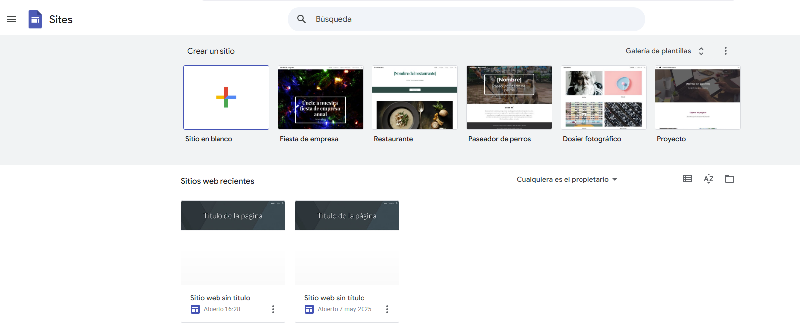
9.-Programming: Interface (web page)
To begin programming the Xiaoesp32-c3 module, we'll start with the interface, as it will allow us to view all the robot's functionality. We'll use the Google Sites tool:
We will upload the HTML Code, once the Code is inserted we click on the following:
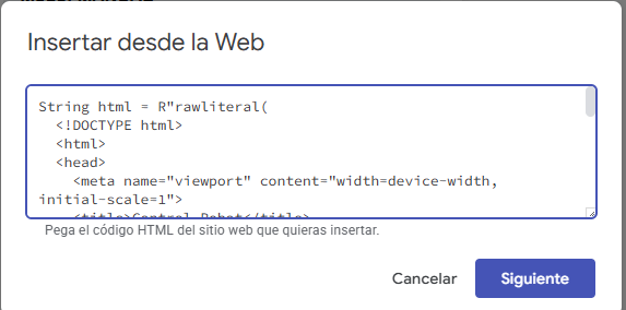
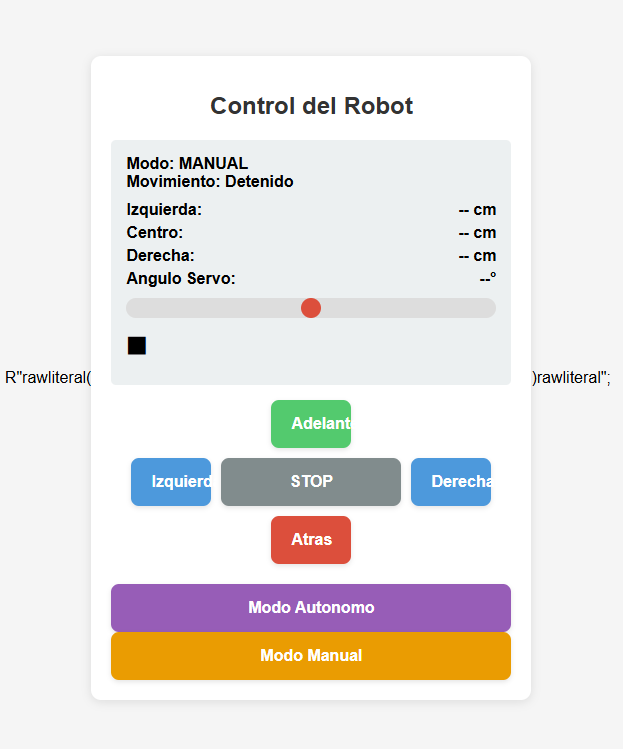
we will have a preview of the interface
10.-System Integration
The integration of the ZentinelBot consisted of uniting the different stages of the project: mechanical design, manufacturing, electronic system, and embedded programming, with the goal of obtaining a functional robot capable of patrolling and detecting activity in real time.
You can view more details in week 15.
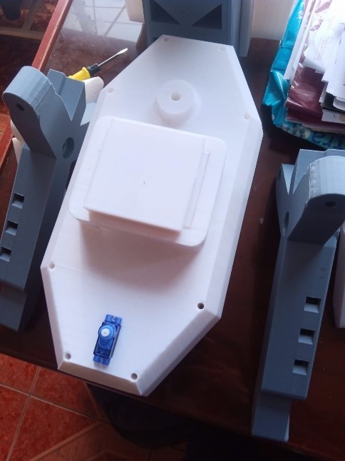
The assembly begins with the joining of the main base, to which the side walls and structural supports are fixed using screws and nuts.
.jpeg)
The first step of assembly was to place the couplings (hubs) that firmly connect each DC motor to its respective wheel.
.jpeg)
After attaching the motors to the wheels, the next step was to assemble the robot's legs (vertical support structures) with the central chassis.
.jpeg)
A custom 3D-printed holder was designed to fit the dimensions of the lead-acid battery used, with slots to secure it firmly without damaging its casing.
.jpeg)
The battery was then securely installed inside the chassis using a specific bracket.
.jpeg)
A protected and accessible area within the chassis was chosen to locate the electronic board (ESP32-C3 Xiao + custom PCB), considering ventilation and space for cables.
.jpeg)
I proceeded to install the electronic card (controller board) inside the chassis.
.jpeg)
To protect the robot's electronic system from possible short circuits or overcurrents, a safety fuse was integrated into the main power supply path.
.jpeg)
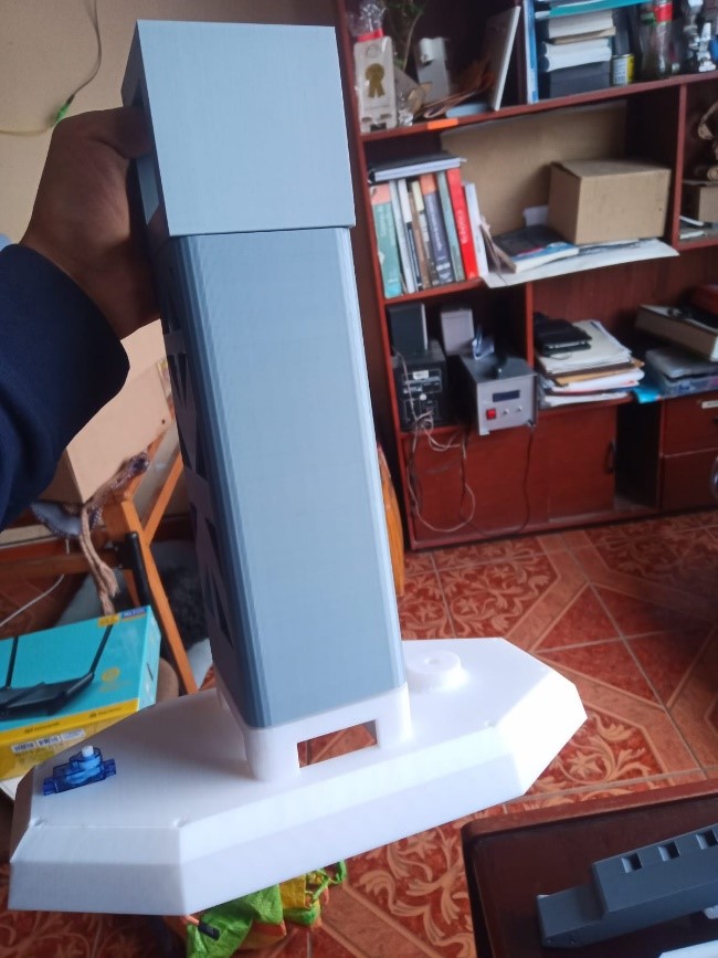
Once the main components were placed inside the chassis, I proceeded to tighten the bolts and screws of the body support, thus securing the mechanical structure of the robot.
.jpeg)
Place the camera antennas inside the designed support
.jpeg)
After integrating all the mechanical and electronic components, the robot assembly was completed.
.jpeg)
We complete the assembly of all the components, and then run the functional tests to validate the system's proper functioning.
The robot assembly was carried out in several stages, beginning with the preparation of the mechanical parts, followed by the integration of the electronic components, and ending with functional testing.
11.-Final Tests
As a result of the tests carried out after assembly, it was verified that the robot correctly executes basic movements through manipulation of the control interface.
Integration Testing Results
As a result of the integration tests performed after the assembly, the robot was able to execute basic movements correctly through the control interface.
Observed Behavior:
- Forward and backward movement with immediate response to the sent commands.
- Left and right turns with accurate directional control.
- Complete stop upon receiving the stop command.
- Proper speed with no loss of traction in the wheels.
Control Interface:
The developed interface (web-based or via Bluetooth BLE) allows wireless command transmission to the ESP32-C3, which interprets the instructions and drives the motors using the L298N module.
Validated Integration:
All systems (electronic, mechanical, and control) work together in sync. The data flow between the interface and the microcontroller is stable, ensuring effective control of the robot's movements.
.jpeg)
.jpeg)
|
The ZentinelBot integrates a dual-lens IP camera that improves its vision by capturing images from two angles simultaneously. Thanks to this technology, the robot can transmit real-time video over Wi-Fi. |
An integrated web interface allows remote control of the robot's motors and real-time viewing of the distance measured by the ultrasonic sensor. |
As a final result, the ZentinelBot effectively integrates mobility, sensing, and remote control systems. Thanks to its dual-lens IP camera, it enables real-time visual monitoring from multiple angles. Its custom web interface offers intuitive motor control and instant visualization of data obtained by the ultrasonic sensor, allowing it to detect obstacles and navigate with greater precision.
Conclusions
The development of the ZentinelBot has been a highly rewarding and comprehensive experience, combining mechanical design, digital manufacturing, electronics, and programming. From the design and 3D printing of the chassis, a robust and modular structure was built that allowed for the proper installation of motors, sensors, and control boards. Once all the parts were assembled, the electronic system was integrated, followed by the loading of the programming code and the execution of functional tests.
Beyond building a robot, I learned to think systemically, iterate quickly, and find solutions within an ecosystem of open and collaborative tools. Every step, from designing the chassis to running final tests, allowed me to better understand the limits and possibilities of local and custom manufacturing.
This project represents not only a technical achievement but also a reflection of the Fab Academy spirit: learning by doing, sharing knowledge, and creating accessible solutions with real impact.
Link to files used this week
1. robot.ino2. left leg.ipt
3. right leg.ipt
4. chest.ipt
5. antenna base.ipt
6. antenna cover.ipt
7. cover.ipt
8. mask.ino
9. mechanism.ipt