
For this week four as a FabAcademy student, the experience has been very nice and unforgettable, eager to learn about embedded systems programming, taking into account the different architectures.
Group Assignment:
- Demonstrate and compare the toolchains and development workflows for available embedded architectures.
- Document your work to the group work page and reflect on your individual page what you learned
Individual Assignment:
- Browse through the datasheet for your microcontroller.
- Write a program for a microcontroller, and simulate its operation, to interact (with local input &/or output devices) and communicate (with remote wired or wireless connection)
What is embedded programming?
An embedded system (also known as “embedded”, “embedded” or “integrated”) is a computing system designed to perform specific functions, and whose components are integrated on a motherboard.

Group Assignment
- Demonstrate and compare the toolchains and development workflows for available embedded architectures.
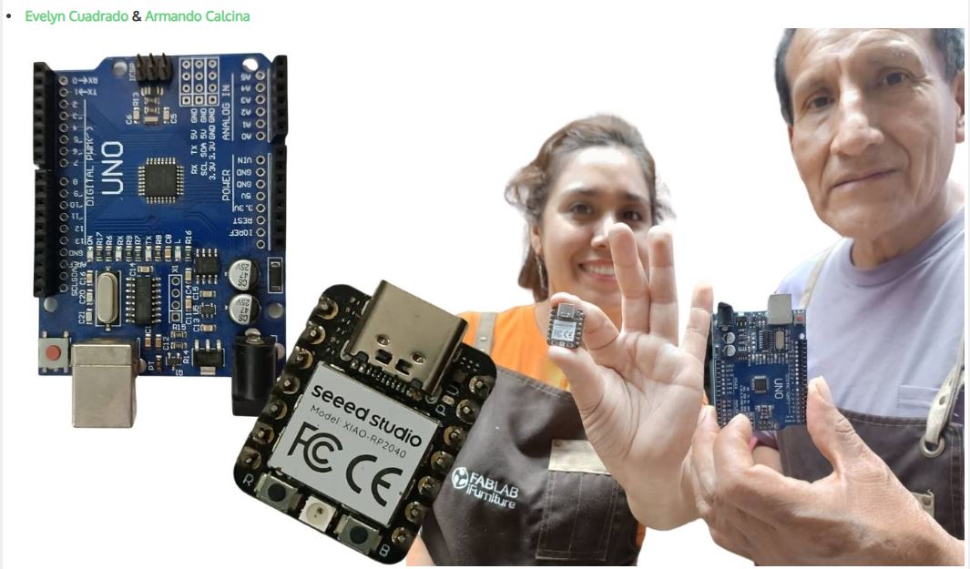
During this week we visited the iFORNITURE fab lab in the city of Lima, we met with Evelin Cuadrado and Cristian to advance the group work, both in computer programming and also to learn about microcontrollers. In this regard, Evelin showed me in person the XIAO RP 2040 microcontroller, in which we identified its characteristics, design and programming. It was a challenge, but we are moving forward. We also discuss the electronics and programming of our projects to be developed.
Reflections
During the group project, I was able to learn more about embedded system architectures, such as toolchains and development workflows for embedded architectures. This involves analyzing how embedded systems are designed, developed, tested, and debugged using different environments. It was a very enriching project; it allowed me to learn and expand my knowledge, allowing me to better understand how different architectures work. Several years ago, I worked with PIC, one of the most classic and popular microcontrollers in the 8-bit PIC series. Although more modern models exist today, it is still very useful for learning basic concepts about embedded systems.
Individual Assignment
- Browse through the datasheet for your microcontroller.
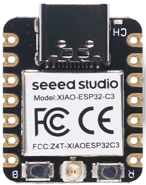
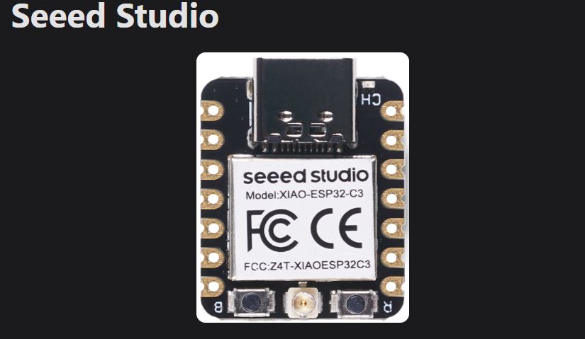
For the development of this task I chose to work with Seeed Studio XIAO ESP32C3 which is a compact and powerful mini IoT development board based on the Espressif ESP32-C3 chip, below I will explore all its data sheet and technical information,For more details, please consult. ESP32C3 series datasheet
Introduction to Seeed Studio ESP32-C3
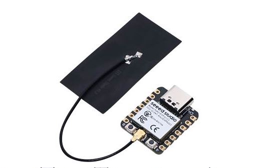
Seeed Studio XIAO ESP32C3 is an IoT mini development board based on the Espressif ESP32-C3 WiFi/Bluetooth dual-mode chip, featuring a 32-bit RISC-V CPU that delivers powerful computing performance with its efficient architecture. It has excellent radio frequency performance, supporting IEEE 802.11 b/g/n WiFi, and Bluetooth 5 (BLE) protocols. This board comes included with an external antenna to increase the signal strength for your wireless applications. It also has a small and exquisite form-factor combined with a single-sided surface-mountable design. It is equipped with rich interfaces and has 11 digital I/O that can be used as PWM pins and 3 analog I/O that can be used as ADC pins. It supports four serial interfaces such as UART, I2C and SPI. There is also a small reset button and a bootloader mode button on the board. XIAO ESP32C3 is fully compatible with the Grove Shield for Seeeduino XIAO and Seeeduino XIAO Expansion board except for the Seeeduino XIAO Expansion board, the SWD spring contacts on the board will not be compatible.
1.-Especifications
| Category | Specification |
|---|---|
| Microcontroller | ESP32-C3 (32-bit RISC-V, up to 160 MHz) |
| Flash Memory | 4 MB |
| SRAM | 400 KB |
| Wireless | Wi-Fi 802.11 b/g/n (2.4 GHz) Bluetooth 5.0 (BLE + Mesh) |
| USB Interface | USB Type-C |
| GPIOs | 11 digital I/O pins All GPIOs support PWM |
| ADC Channels | 4 channels (12-bit resolution) |
| Interfaces | 1 × UART 1 × I2C 1 × SPI |
| Operating Voltage | 3.3 V |
| Power Supply | 5 V via USB or external source |
| Current Consumption |
Deep Sleep: ~44 µA Light Sleep: ~10 mA Active with Wi-Fi: ~75 mA |
| Charging Current | 100 mA / 350 mA (configurable) |
| Reset Button | Yes |
| Boot Button | Yes |
| Dimensions | 21 mm x 17.5 mm |
| Operating Temperature | -40 °C to 85 °C |
| Weight | 2 g (approx.) |
| Development Support | Arduino, PlatformIO, ESP-IDF, MicroPython |
2.-Features and details
- It can operate in station mode, SoftAP mode, with a combination of both, or in promiscuous mode for multiple Wi-Fi applications. In addition, it supports Bluetooth 5 and Bluetooth mesh functionalities.
- The XIAO ESP32C3 MCU board mounts the ESP32-C3 chip, which operates at a clock frequency of 160 MHz. It has multiple development ports and Arduino/CircuitPython support
- It has four work modes, with energy consumption as low as 44 μA in deep sleep mode. For its power, it supports charging from a lithium battery, and its design allows it to be mounted on a breadboard, in addition to supporting SMD design, since it does not have components on the back
- The chip also includes 400 KB of SRAM and 4 MB of flash memory, providing more programming space and more possibilities in IoT control scenarios
3.-.-Hardware overview
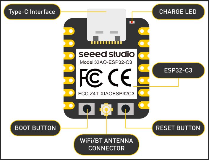
1.-XIAO ESP32C3 front indication diagram
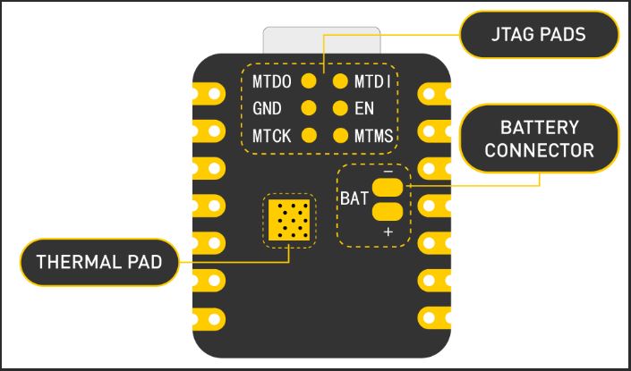
2.-XIAO ESP32C3 back indication diagram
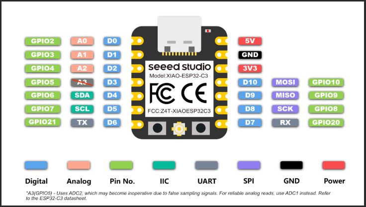
4.-Pin Out
4.1 Power Pins
- 5V - This is 5v out from the USB port. You can also use this as a voltage input but you must have some sort of diode (schottky, signal, power) between your external power source and this pin with anode to battery, cathode to 5V pin.
- 3V3 - This is the regulated output from the onboard regulator. You can draw 700mA
- GND - Power/data/signal ground
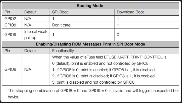
4.2 Strapping Pins
According to the chip manual of ESP32C3, GPIO2, GPIO8 and GPIO9 in the chip are Strapping Pins, the high and low level configurations of these pins may allow the chip to enter into different Boot modes, please pay attention to this point when you use these pins, otherwise it may prevent your XIAO from uploading or executing the program all the time.
- Write a program for a microcontroller, and simulate its operation, to interact (with local input &/or output devices) and communicate (with remote wired or wireless connection)
Programming with the ESP32C3 microcontroller
Analyzing the technical characteristics of the XIAO ESP32C3 microcontroller from Seeed Studio, it is a miniature IoT development board based on the dual WiFi/Bluetooth ESP32-C3 chip from Espressif. The ESP32-C3 is a 32-bit RISC-V CPU, which includes an FPU (Floating Point Unit) for 32-bit single-precision arithmetic with high computing power. It has excellent radio frequency performance, supporting the IEEE 802.11 b/g/n WiFi and Bluetooth (BLE) protocols. This board includes an external antenna to increase signal strength in your wireless applications. It also has a small and exquisite format combined with a single-side surface mount design. It is equipped with rich interfaces and has 11 digital I/O pins that can be used as PWM pins and 3 analog I/O pins that can be used as ADC pins. Which will serve to develop my final project, which consists of designing and manufacturing a police robot to provide security.
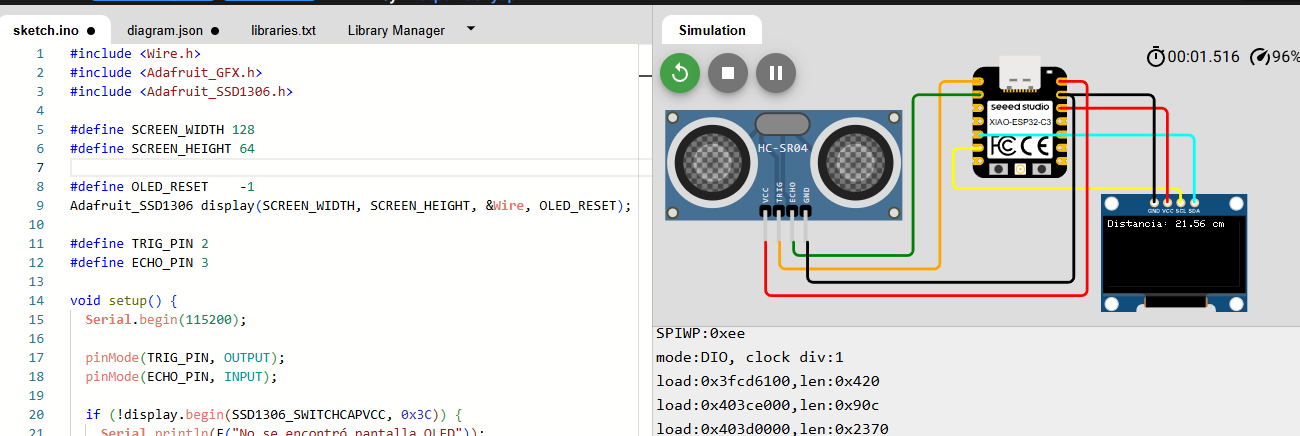
Simulation using HC-SR04 ultrasonic sensor, to measure distance and display it on serial monitor
The circuit is shown as follows
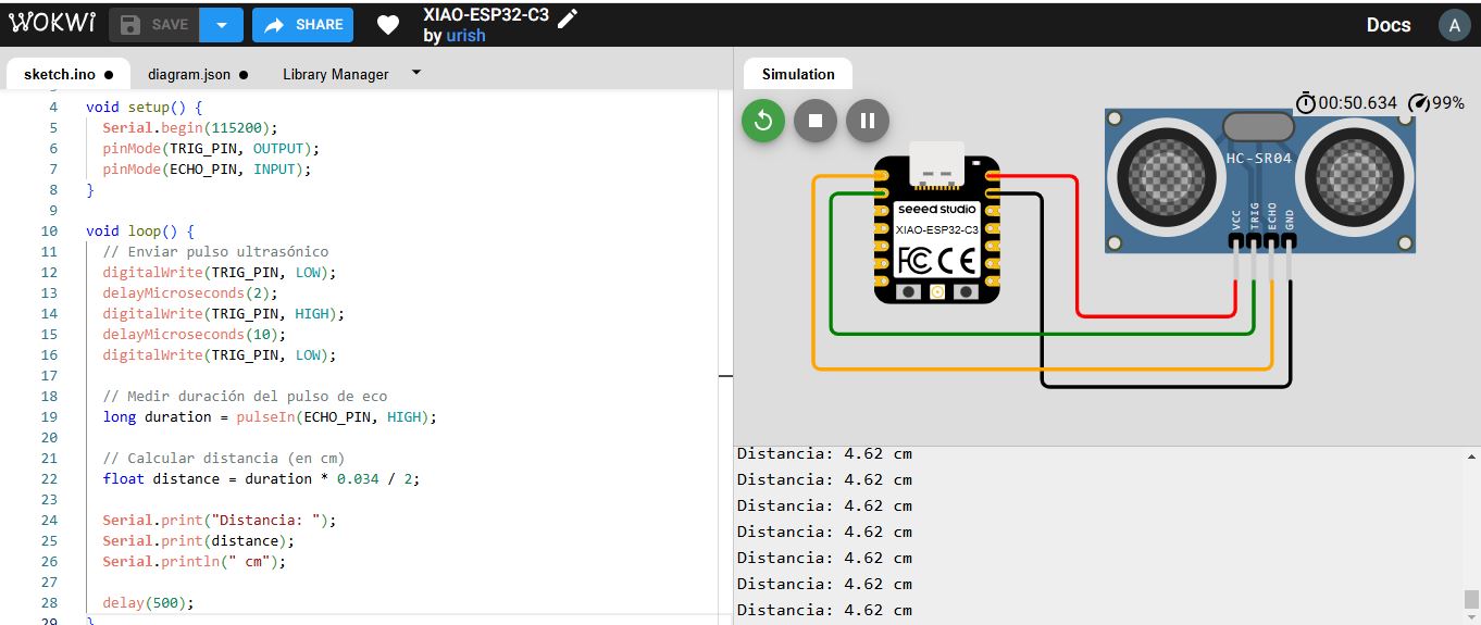
Explanation of the code
1. Define the sensor pins
#define TRIG_PIN 3  // Pin GPIO 03 of the XIAO ESP32C3
#define ECHO_PIN 2  // Pin GPIO 02 of the XIAO ESP32C3
- TRIG_PIN: Sends the ultrasonic pulse.
- ECHO_PIN: Listens for the returning echo.
2. Setup function
void setup() {
	Serial.begin(115200);
	pinMode(TRIG_PIN, OUTPUT);
	pinMode(ECHO_PIN, INPUT);
}
- Serial.begin(115200): Starts the serial monitor for debugging.
- pinMode(...): Sets TRIG as output and ECHO as input.
3. Loop function — measure distance continuously
void loop() {
🟢 Send the ultrasonic pulse
	digitalWrite(TRIG_PIN, LOW);
	delayMicroseconds(2);
	digitalWrite(TRIG_PIN, HIGH);
	delayMicroseconds(10);
	digitalWrite(TRIG_PIN, LOW);
- First, make sure the TRIG pin is LOW for 2 microseconds (stabilization).
- Then send a HIGH signal for 10 microseconds — this triggers the ultrasonic burst.
- Finally, set TRIG to LOW again.
⏱️ Measure echo duration
long duration = pulseIn(ECHO_PIN, HIGH);
- pulseIn(...): Measures how long the ECHO pin stays HIGH (i.e., how long the sound took to bounce back).
- The value is returned in microseconds (µs).
📏 Convert time to distance
float distance = duration * 0.034 / 2;
- The speed of sound is approximately 0.034 cm per microsecond.
- Divide by 2 because the sound travels to the object and back (round trip).
Print the result:
if (duration == 0) {
	Serial.println("No response from sensor");
} else {
	Serial.print("Distance: ");
	Serial.print(distance);
	Serial.println(" cm");
}
implementation of the circuit in physics
Once the simulation is done, we can check the operation of the circuit, now we start to build our circuit.
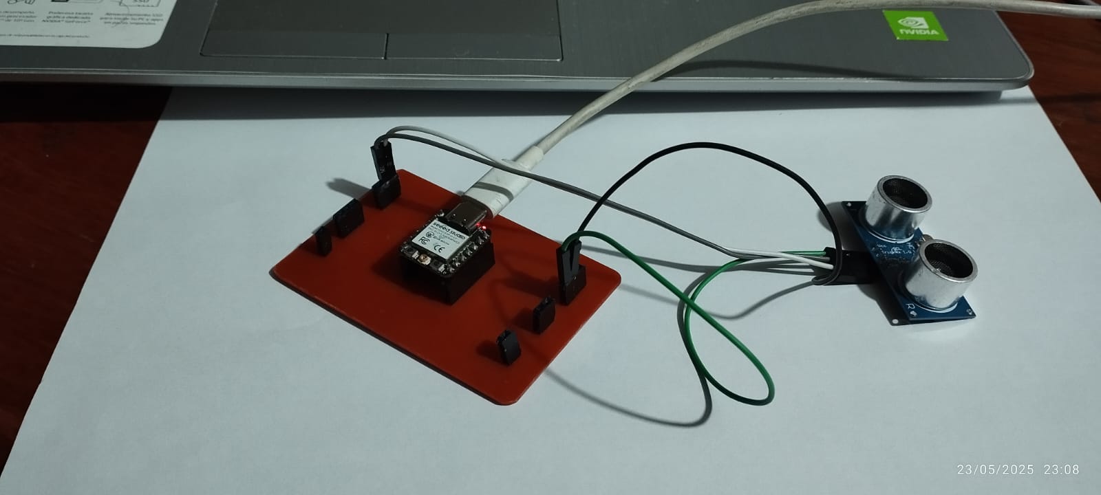
We connect the HC-SR04 ultrasonic sensor to the microcontroller board.
Later we connect the development board to the PC, through the USB cable.
Once the development board is connected, we will make the configurations in Arduino IDE, to load the code and then view the transmission of measured data from the microcontroller to the PC.
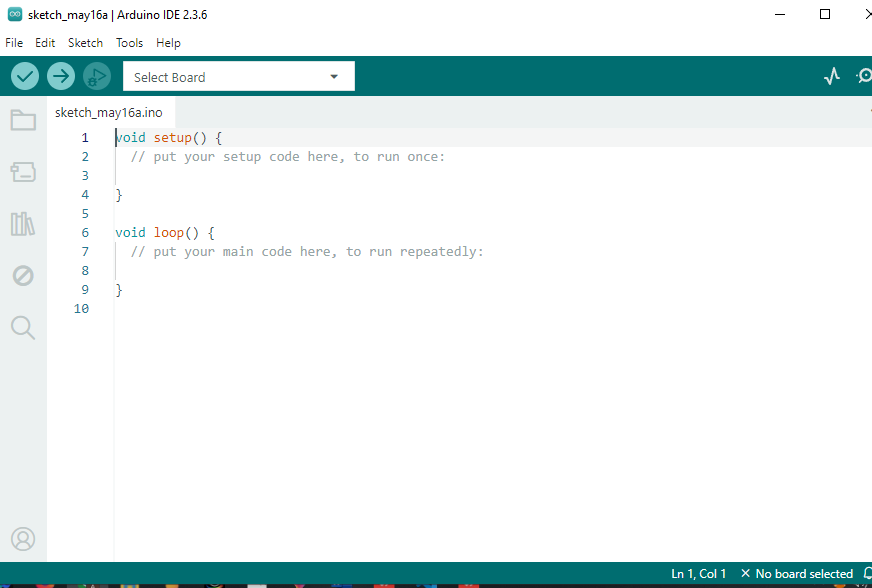
Environment Setup
- Open the Arduino IDE.
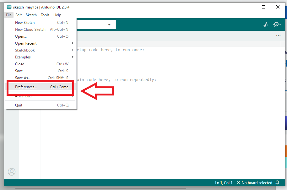
- We install the ESP32 board package by doing the following:
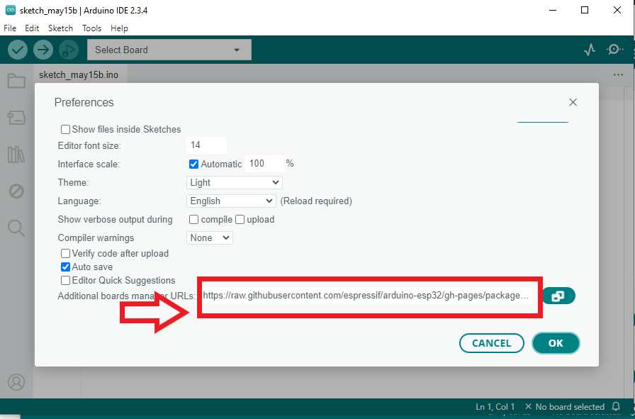
- then we will File > Preferences and add the following URL to Additional Boards Manager URLs:
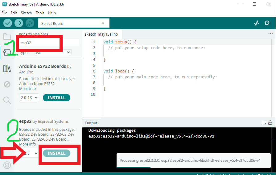
https://espressif.github.io/arduino-esp32/package_esp32_index.json - let's openBoards Manager from Tools > Board > Boards Manager.
- We search "ESP32" and install the package by Espressif Systems.
- then we will File > Preferences and add the following URL to Additional Boards Manager URLs:
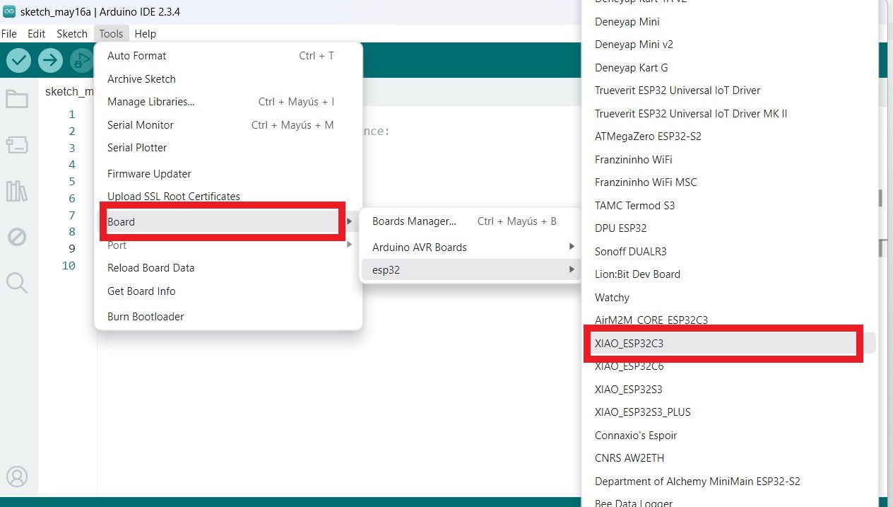
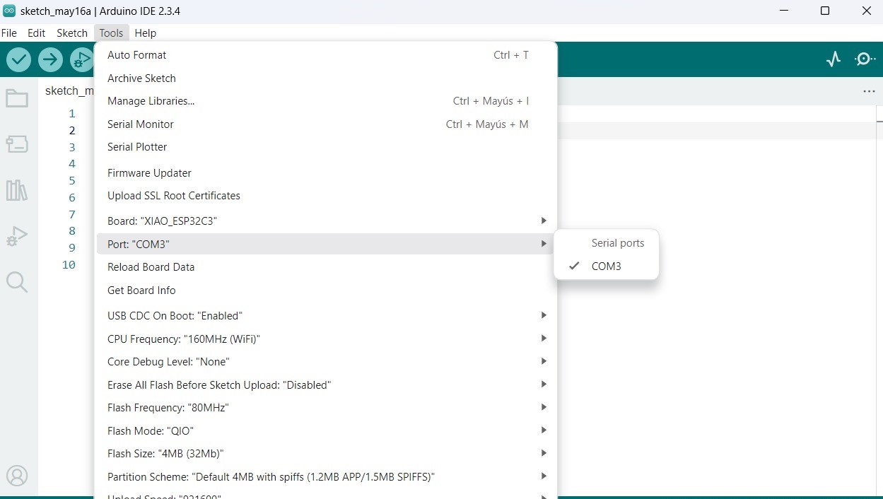
- Select the board:
Tools > Board > ESP32S3 Dev Module(or XIAO ESP32C3 if available). - Select the correct COM port (USB connection) from:
Tools > Port.
according to the images shown below:
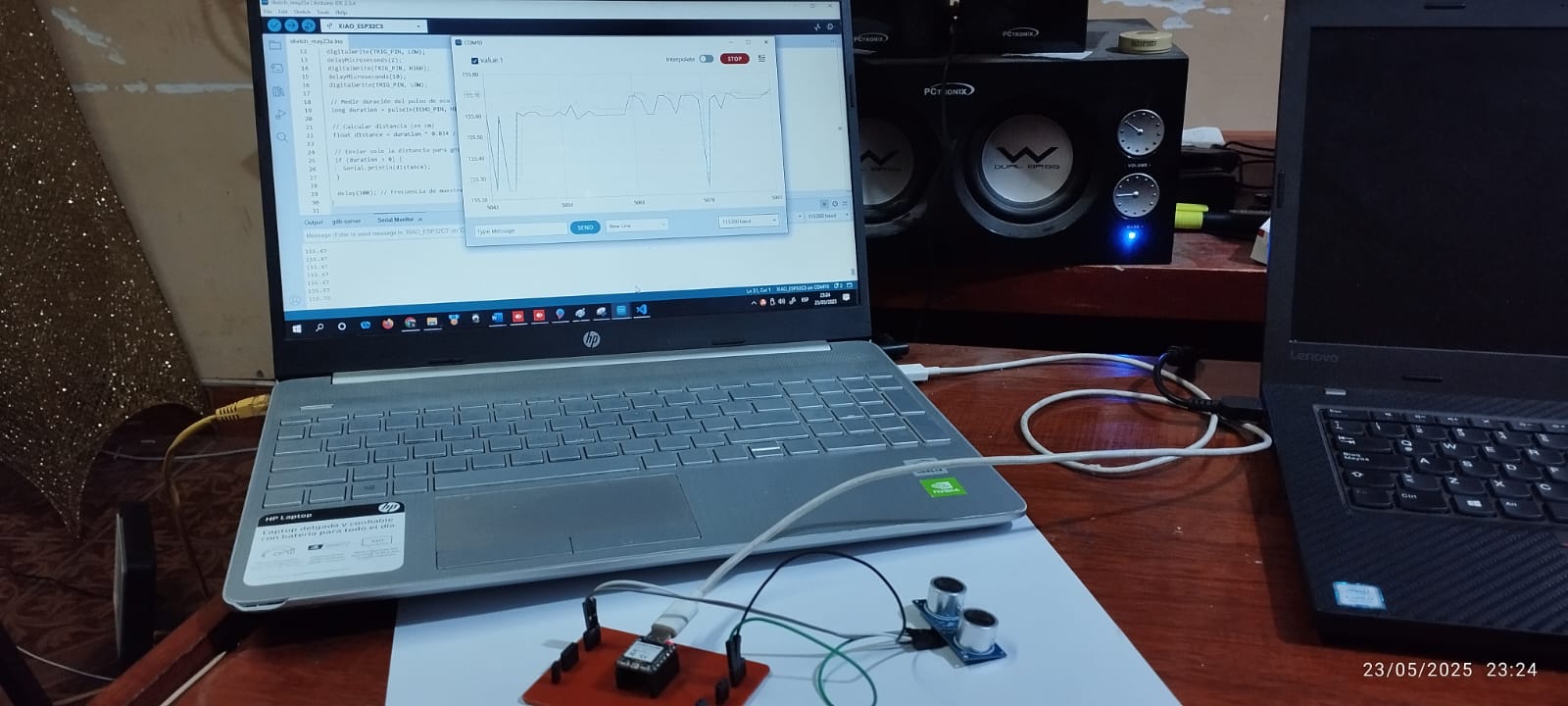
🔍 Visualizing results:
Once the code is compiled and loaded, we proceed to observe the data displayed by the sensor.
During program execution, the system successfully measured the distance using the HC-SR04 ultrasonic sensor and the XIAO ESP32-C3 microcontroller. The output was displayed in the Serial Monitor of the Arduino IDE via local wired communication (USB). To verify the sensor's proper operation, a practical test was performed: the hand was brought close to the sensor at different distances. The obtained values were updated in real time, displaying the measured distance in centimeters on the screen.
Controlling a DC motor with ESP32-C3 XIAO (direction and stop)
The objective of the exercise is to control a direct current (DC) motor with the ESP32-C3 XIAO microcontroller, so that it: Rotates in one direction (forward), Stops, Rotates in the other direction (reverse), Stops and repeats this cycle indefinitely. This exercise will help us develop our final project, which consists of building a police robot. This project will consist of four motors; for this exercise, the test will be done with a single motor.
Parts Required
- ESP32-C3 XIAO
- DC Motor
- H-Bridge Module (such as L298N, L9110, L293D, etc.)
- Power supply for the motor (e.g., 6V or 12V)
- Dupont wires and/or a breadboard
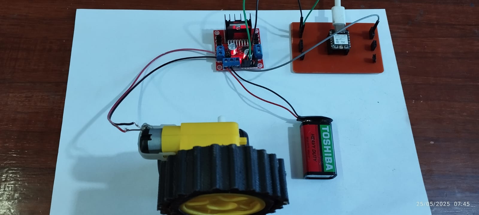
To complete the exercise, we need the components shown
how it Works
The H-bridge receives control signals from the ESP32-C3 XIAO via pins IN1 and IN2. Depending on the combination of these signals, the motor rotates forward, reverse, or stops. The control logic is shown in the table.
| IN1 | IN2 | Motor Action |
|---|---|---|
| 1 | 0 | Rotates forward |
| 0 | 1 | Rotates backward |
| 0 | 0 | Motor stopped |
| 1 | 1 | Brake (depends on driver) |
Programming Code
#include <Arduino.h>

const int IN1 = 2; // GPIO2 of the ESP32-C3 XIAO
const int IN2 = 4; // GPIO4 of the ESP32-C3 XIAO

void setup() {
    Serial.begin(115200);
    pinMode(IN1, OUTPUT);
    pinMode(IN2, OUTPUT);
}

void loop() {
    Serial.println("Motor forward");
    digitalWrite(IN1, HIGH);
    digitalWrite(IN2, LOW);
    delay(2000);

    Serial.println("Motor stopped");
    digitalWrite(IN1, LOW);
    digitalWrite(IN2, LOW);
    delay(1000);

    Serial.println("Motor backward");
    digitalWrite(IN1, LOW);
    digitalWrite(IN2, HIGH);
    delay(2000);

    Serial.println("Motor stopped");
    digitalWrite(IN1, LOW);
    digitalWrite(IN2, LOW);
    delay(1000);
}
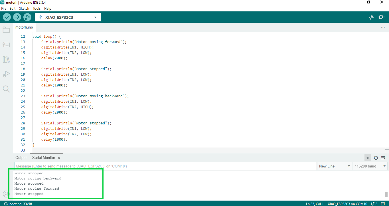
XIAOESP32-C3 with Arduino IDE
Once opened in the Arduino IDE environment, we proceed to load the code for motor control, recognizing the XIAOESP32-C3 board and subsequently identifying the communication port, in my case COM10.
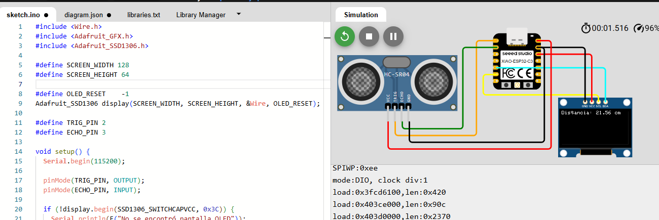
Simulation of XIAO ESP32-C3 with SSD1306 OLED display on Wokwi
For this simulation we will use the I2C communication protocol, which is a very common type of synchronous serial communication in electronics to connect microcontrollers with peripherals such as sensors, displays, memories, etc.
components to use
- SSD1306 OLED Display (I2C)
- HC-SR04 Sensor (distance)
- XIAO ESP32-C3
We will explain step by step
The circuit is shown as follows
explanation of the programming
- At startup, the microcontroller configures the pins for the ultrasonic sensor and OLED display.
- A startup message is displayed on the OLED to indicate the system is ready.
- The microcontroller sends a short pulse (10 microseconds) to the
TRIGpin of the HC-SR04 sensor. - The sensor emits an ultrasonic wave that bounces off the nearest object.
- When the wave returns, the sensor sets the
ECHOpin high; the duration of this signal represents the round-trip travel time of the sound wave. - The microcontroller measures that duration and calculates the distance using the formula:
distance = (duration × 0.034) / 2 - The measured distance is displayed on the OLED screen and also printed to the serial monitor.
- This process repeats continuously every 500 milliseconds.
This operation allows real-time distance measurement of any object in front of the sensor. It's ideal for projects like proximity detectors, smart parking systems, robotics, and more.
Program developed in the Arduino IDE, with RP2040-Zero microcontroller
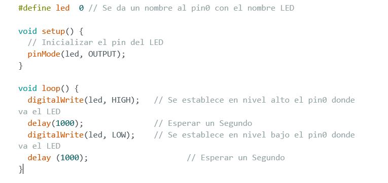
RP2040-Zero Microcontroller: In the present project, a program developed in the Arduino 2.3.4 IDE has been developed to control the blinking of an LED connected to pin 0 of the RP2040-Zero board. The implemented code allows the LED to alternate between on and off states with precise one-second intervals.
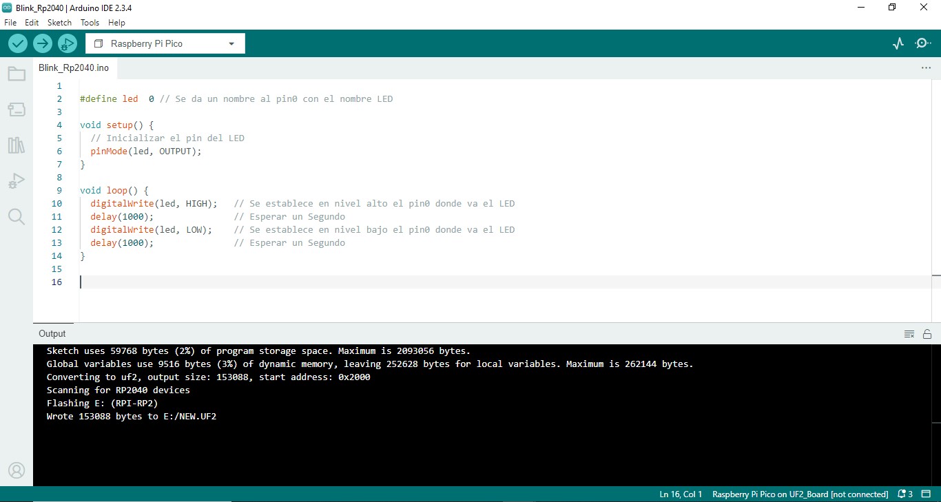
Code in Arduino IDE
Flash the LED RP2040-Zero Microcontroller
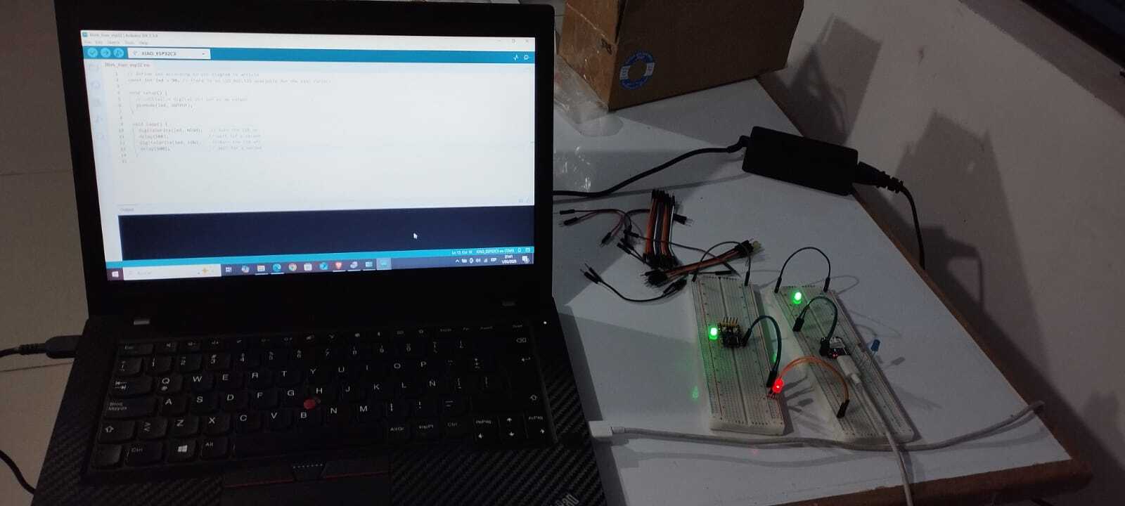
XIAO ESP32 C3 Microcontroller: In the present project, a program developed in the Arduino 2.3.4 IDE has been developed to control the blinking of an LED connected to the D0 pin on the XIAO ESP32 C3 board. The implemented code allows the LED to alternate between on and off states with precise half-second intervals.
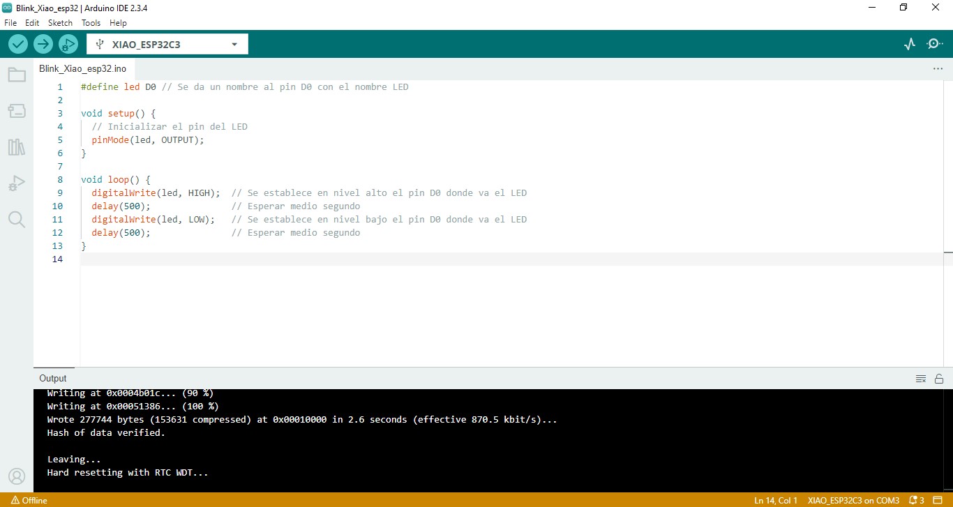
Code in Arduino IDE.
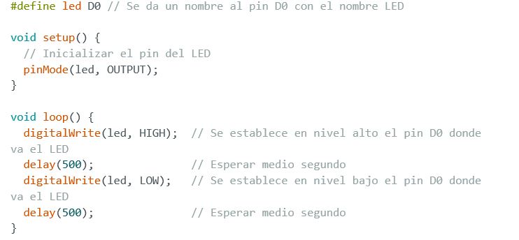
Flash the LED XIAO ESP32 C3 Microcontroller
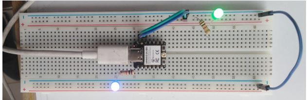
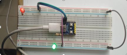
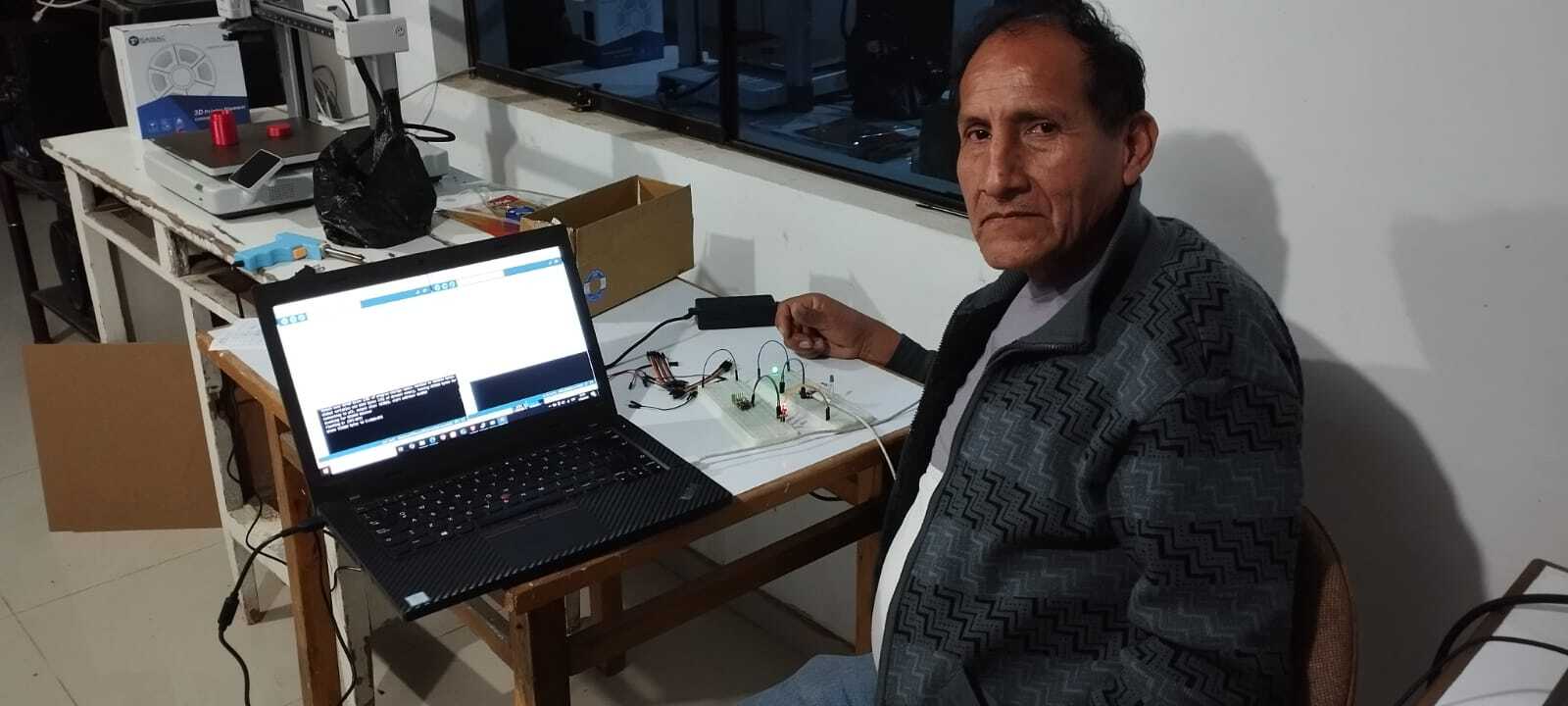
The following image shows my person at the work table carrying out the code in the Arduino IDE and it is observed that the connected LED blinks with a delay of 1 second between each blink. This means that the connection is successful and now you can explore more projects with XIAO ESP32C3.
Conclusions:
In conclusion, microcontrollers are electronic devices that integrate a microprocessor, memory, input/output peripherals, among other components necessary to carry out specific tasks. One of the main advantages of microcontrollers is the ability to be programmed; Such programming is the process by which the software that controls the operation of the microcontroller and its peripherals in order to perform a specific task.
Link to files used this week
1. LED with push button.ino
2.-ultrasonic sensor.ino
3.-I2C communication with SSD1306 OLED display
4.-engine.ino