
Design and document the system integration for your final project
Have you answered these questions?
- implemented methods of packaging? ✅
- designed your final project to look like a finished product? ✅
- documented system integration of your final project? ✅
- linked to your system integration documentation from your final project page? ✅
Project Design
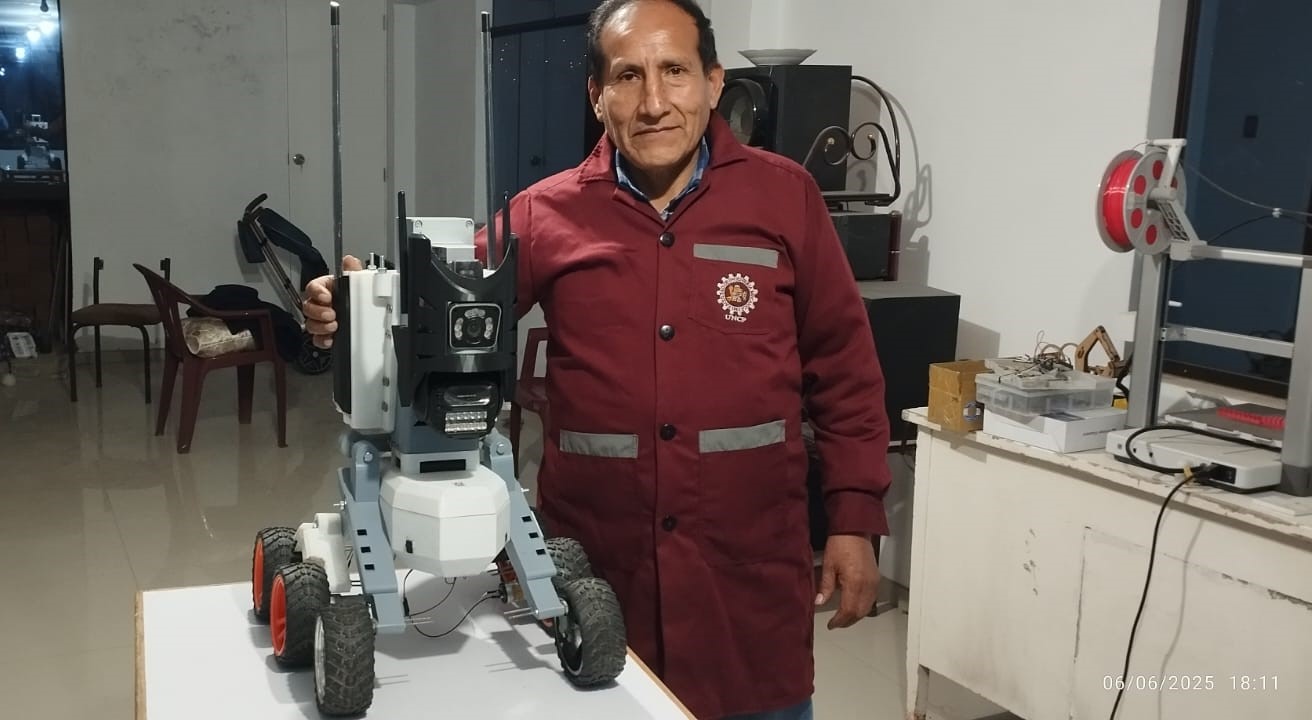
Systems integration is a key stage in the development of the ZentinelBot project, where the various electronic, mechanical, and software components are connected and synchronized to work together. In this phase, the sensors, actuators, microcontroller, and custom electronic board were configured, allowing the robot to function as an efficient, autonomous surveillance system.
1.-Mechanical design
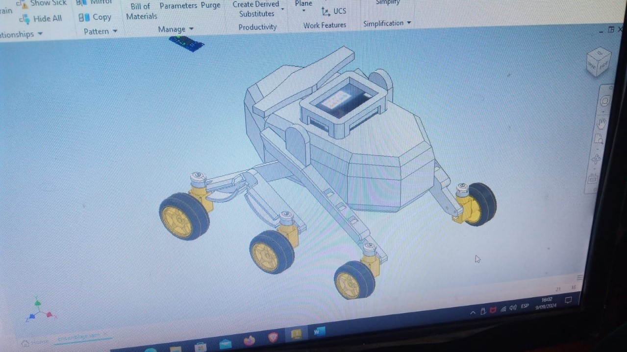
The robot's structure combines the all-terrain mobility principles of space rovers with the structural efficiency of natural organisms, achieving a design that is not only robust and adaptable, but also aerodynamic. In this research, Autodesk Inventor software with generative design tools is used to optimize the structure's weight and strength.
1.1 Structural system
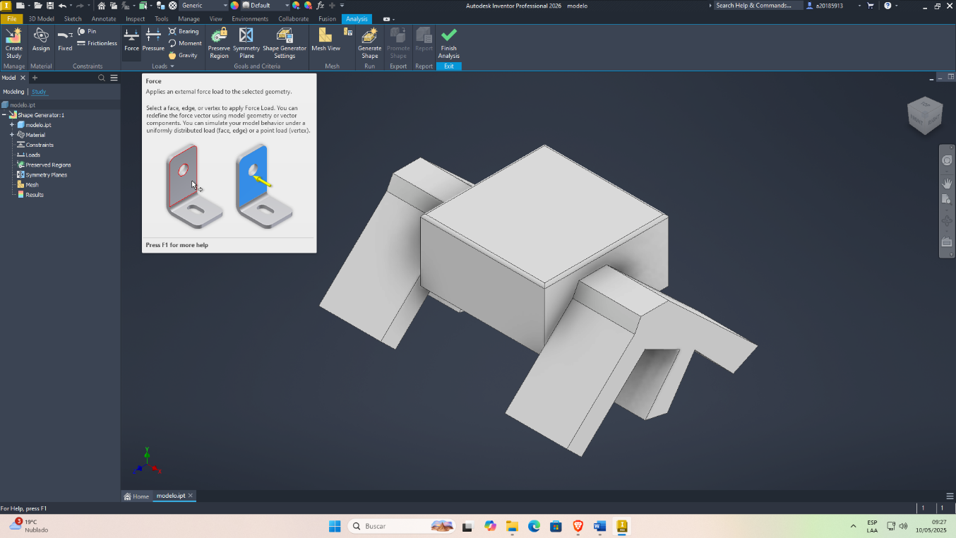
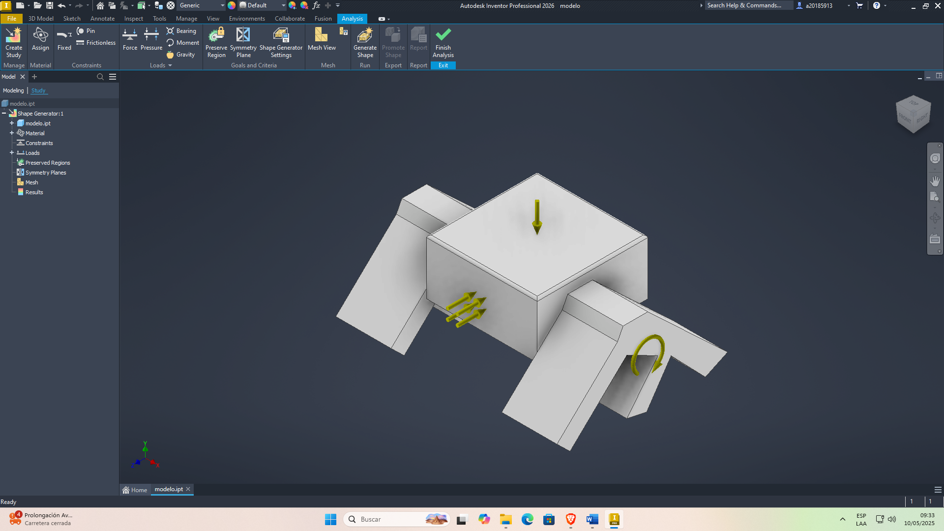
Once the working parameters have been set, we will proceed to load the generative design calculation:
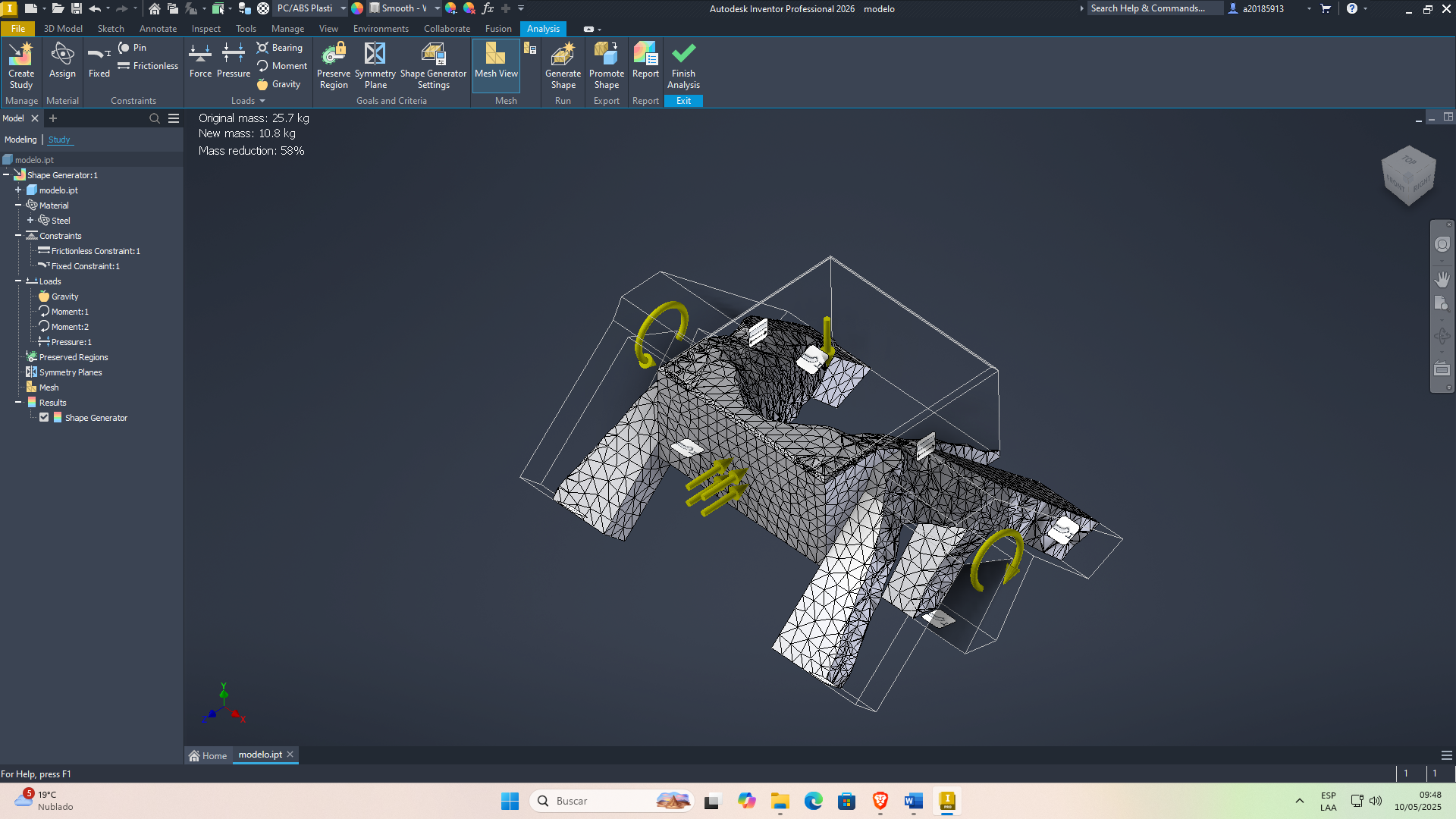
obtaining the preliminary model
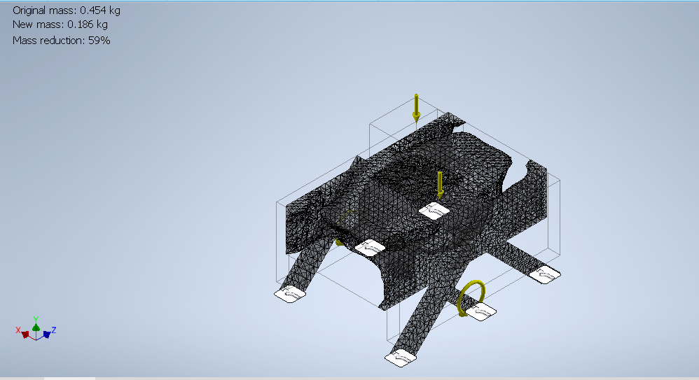
First generative isometric chassis design.
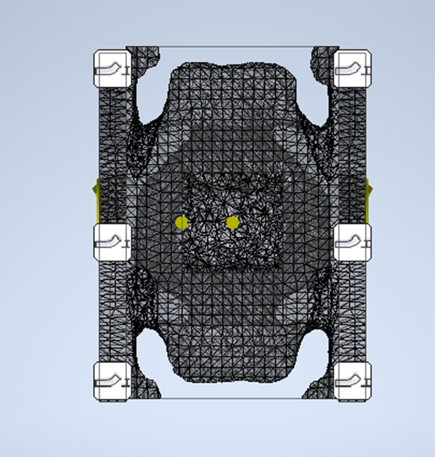
First generative design, chassis plan view.
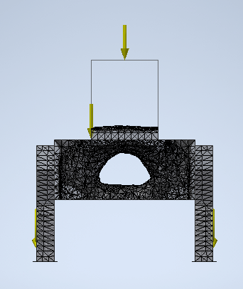
First generative design, bottom view of the chassis.
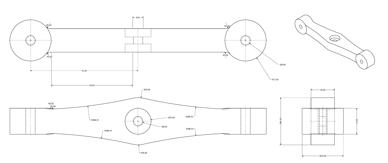
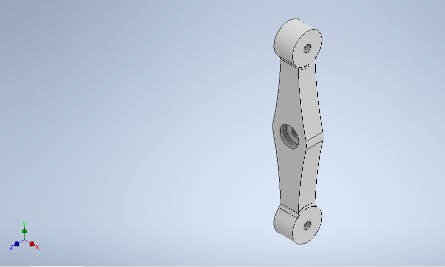
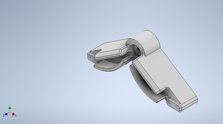
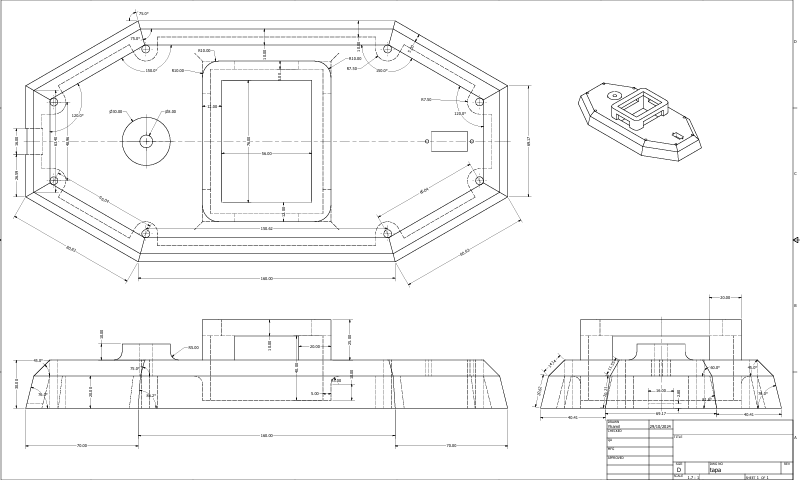
1.2 Link and joint design
Piece 1: unions
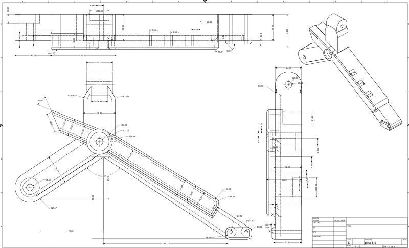
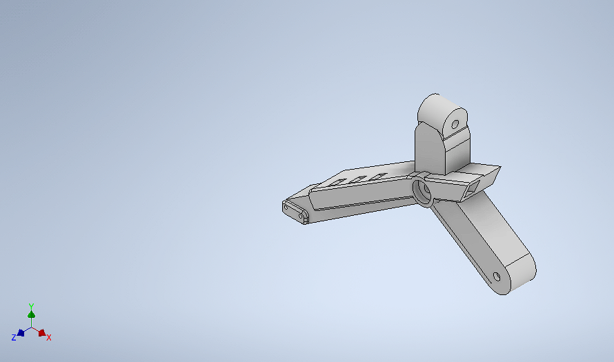
Piece 2: first leg
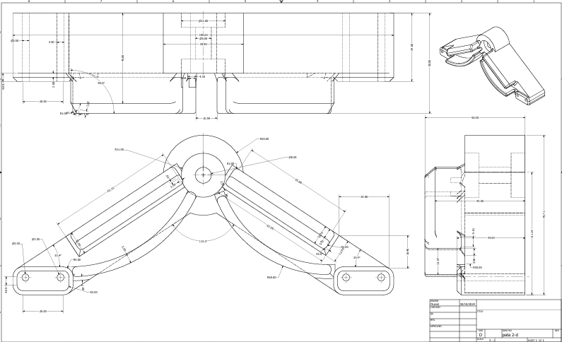
Piece 3: Second leg
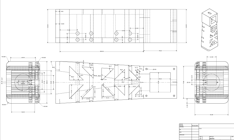
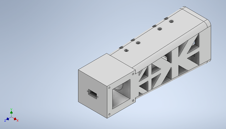
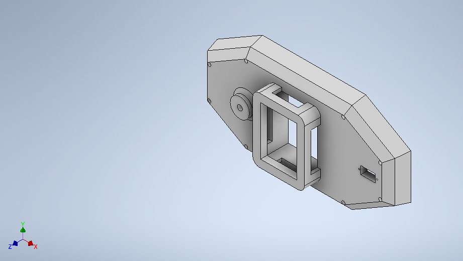
Piece 4: Chest design
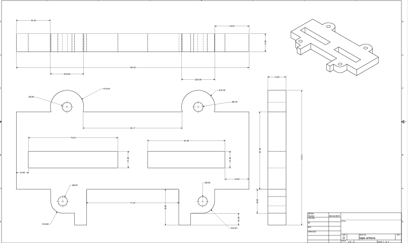
Piece 5: Antenna cover
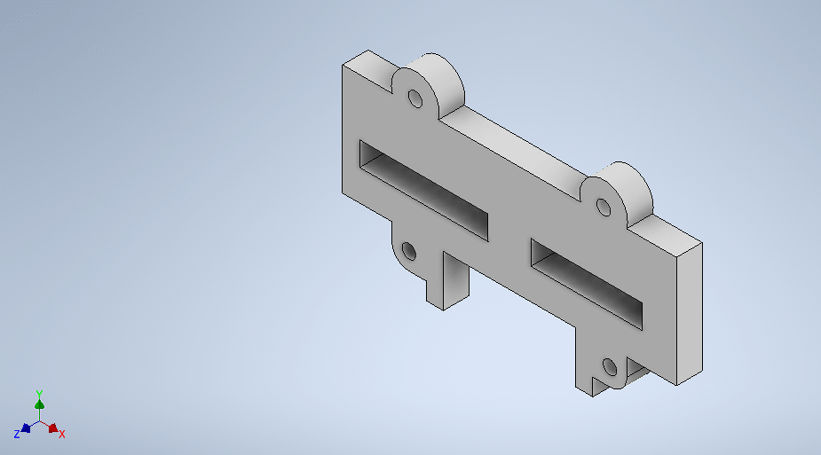
Piece 6: Cover
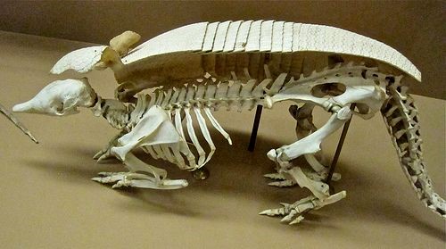
1.3 Biomimicry design
The design process focused on reducing the chassis's weight and volume through the application of biomimicry, i.e., imitating solutions that already exist in nature. In this case, the shape and organization of the armadillo's bone structure were studied in detail. This animal's natural armor allows it to withstand impacts while remaining agile.
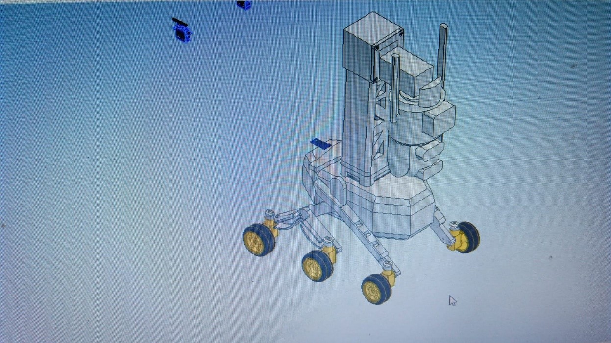
main structure
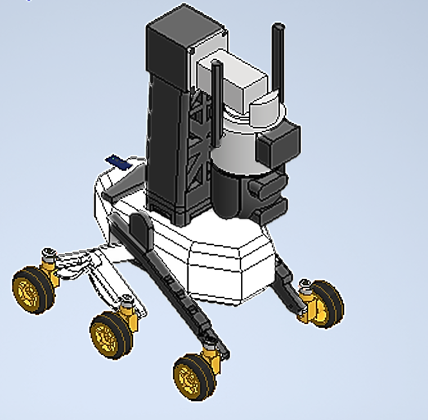
preliminary robot design
2. Manufacturing of parts
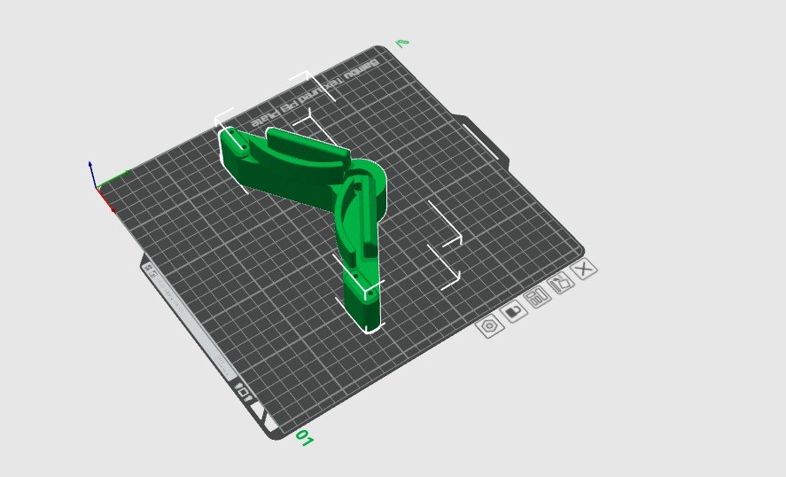
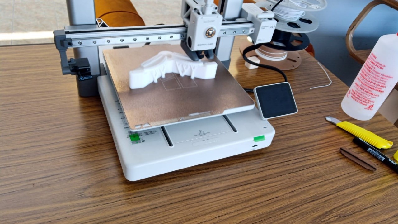
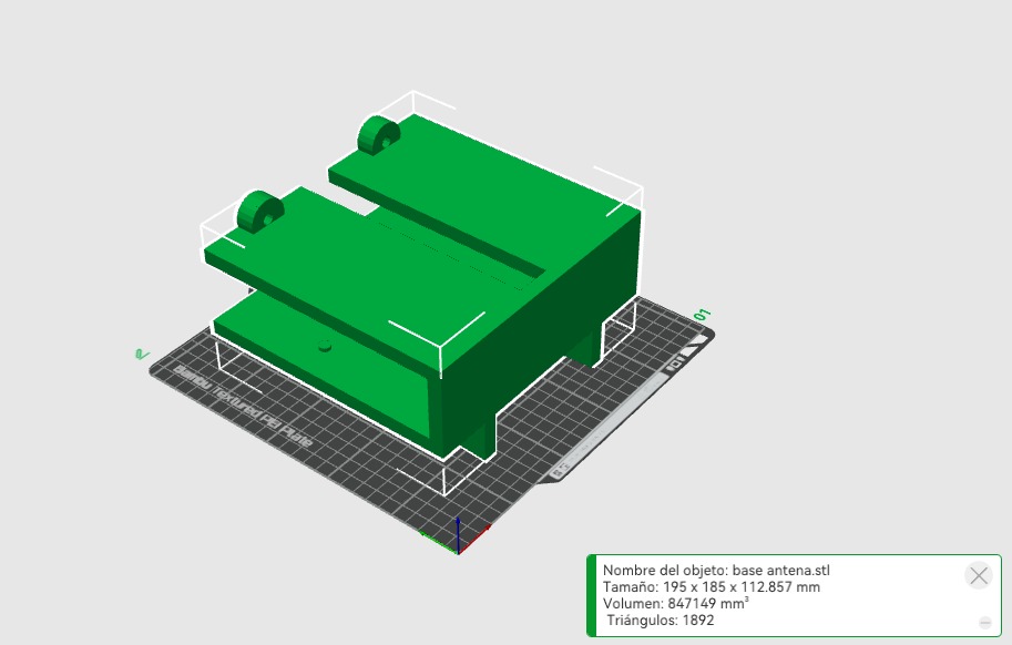
3D printing of parts
For printing the parts, we have exported the generated files in STL format. For printing small parts, the Bambu Lab printer was used, and for larger parts, the Proxy printer was used.
3.-Electronic Integration
To perform electronic integration, we must make a list of the components we will use for the project:
- XIAO ESP32-C3
- ROB-14450 – Motor driver
- L7805CV – Voltage regulator
- Polarized capacitor
- Ultrasonic sensor
- Servomotor
- WS2812B LED strip
3.1 schematic diagram
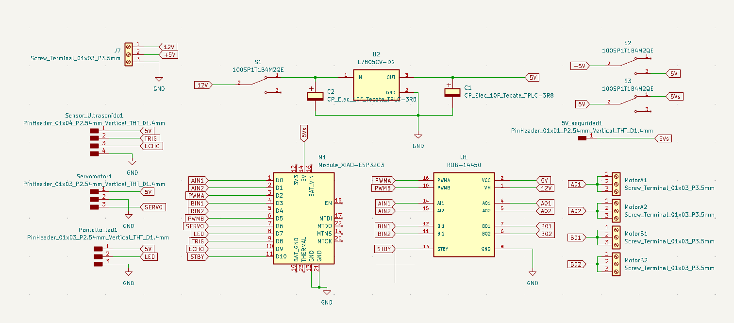
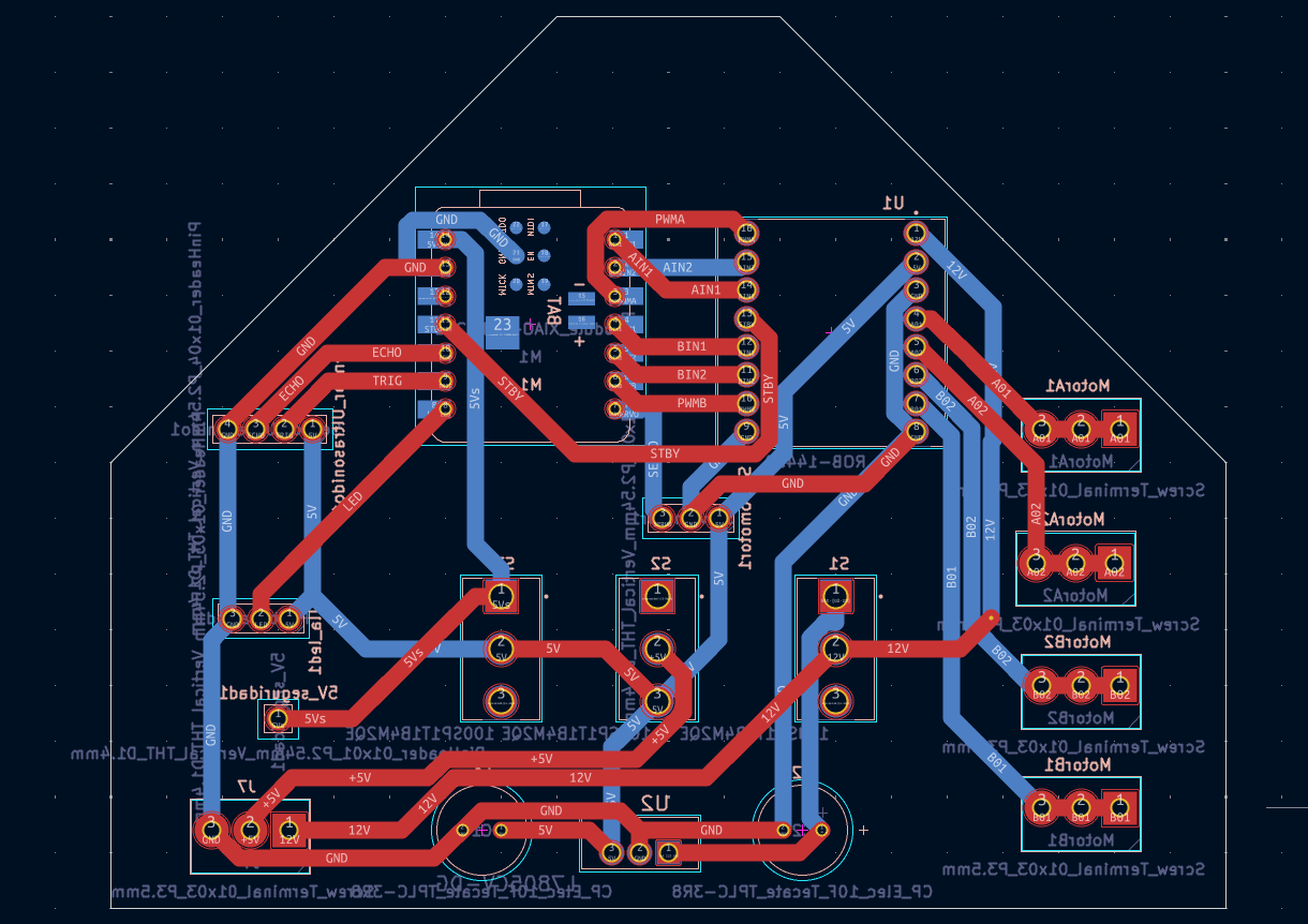
3.2 PCB layout design
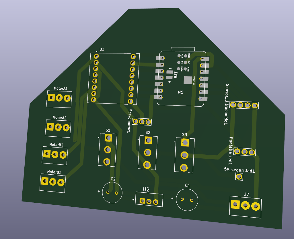
3.2 3D visualization
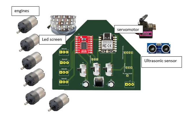
3.3 Component layout
4.- Component Assembly
.jpeg)
The first step of assembly was to place the couplings (hubs) that firmly connect each DC motor to its respective wheel.
.jpeg)
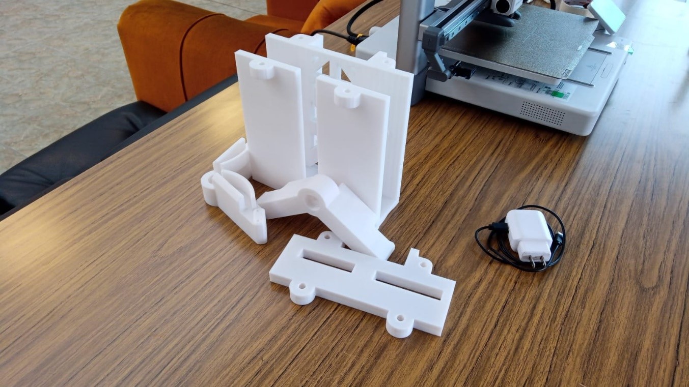
After attaching the motors to the wheels, the next step was to assemble the robot's legs (vertical support structures) with the central chassis.
.jpeg)
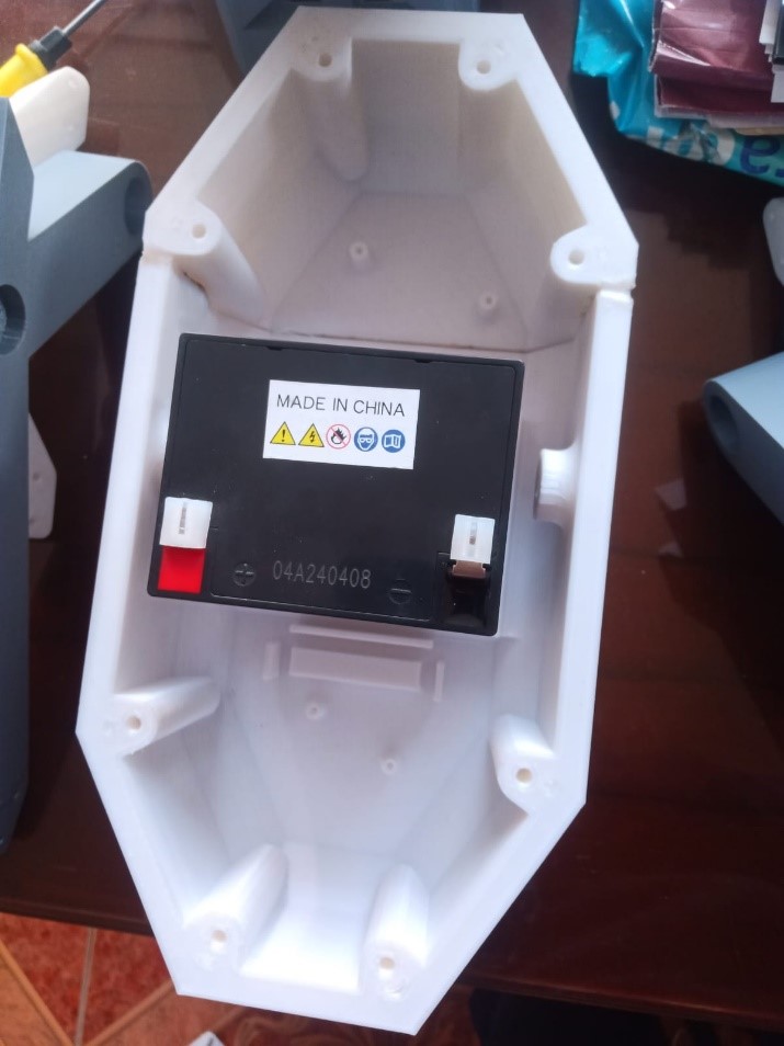
A custom 3D-printed holder was designed to fit the dimensions of the lead-acid battery used, with slots to secure it firmly without damaging its casing.
.jpeg)
The battery was then securely installed inside the chassis using a specific bracket.
.jpeg)
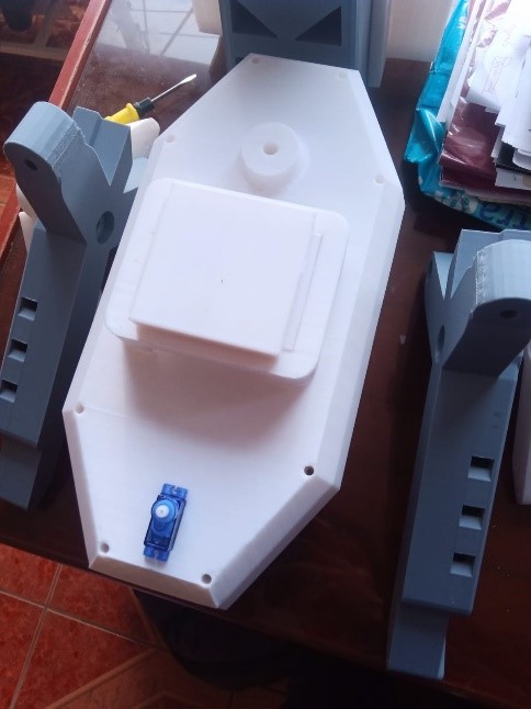
A protected and accessible area within the chassis was chosen to locate the electronic board (ESP32-C3 Xiao + custom PCB), considering ventilation and space for cables.
.jpeg)
I proceeded to install the electronic card (controller board) inside the chassis.
.jpeg)
To protect the robot's electronic system from possible short circuits or overcurrents, a safety fuse was integrated into the main power supply path.
.jpeg)
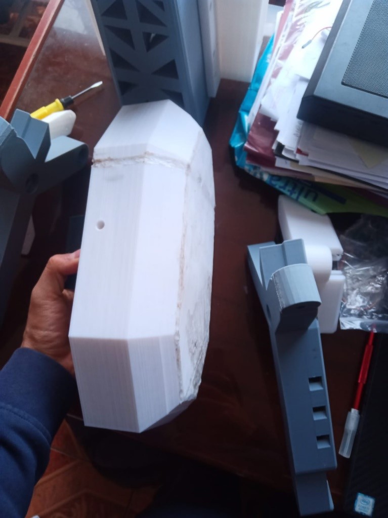
Once the main components were placed inside the chassis, I proceeded to tighten the bolts and screws of the body support, thus securing the mechanical structure of the robot.
.jpeg)
Place the camera antennas inside the designed support
.jpeg)
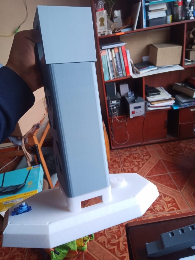
After integrating all the mechanical and electronic components, the robot assembly was completed.
.jpeg)
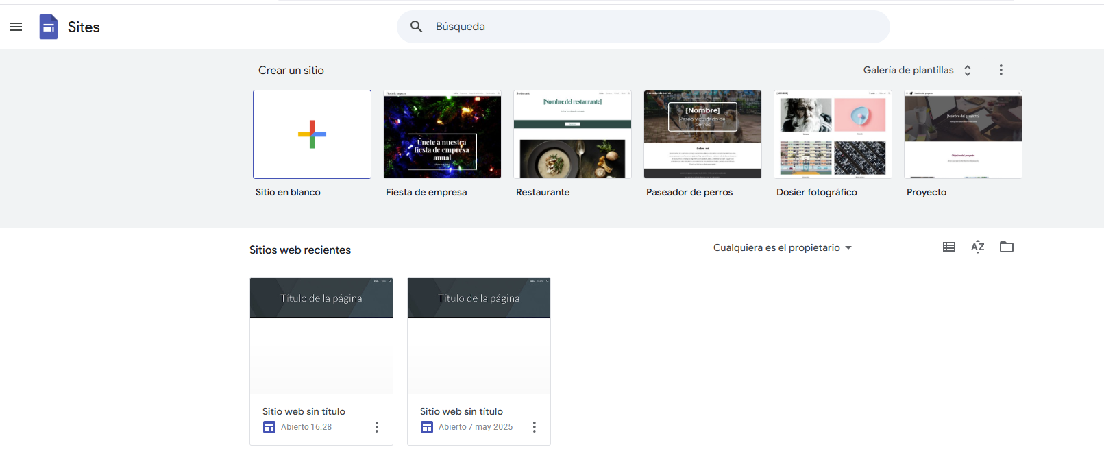
5.-Programming: Interface (web page)
To begin programming the Xiaoesp32-c3 module, we'll start with the interface, as it will allow us to view all the robot's functionality. We'll use the Google Sites tool:
We will upload the HTML Code, once the Code is inserted we click on the following:
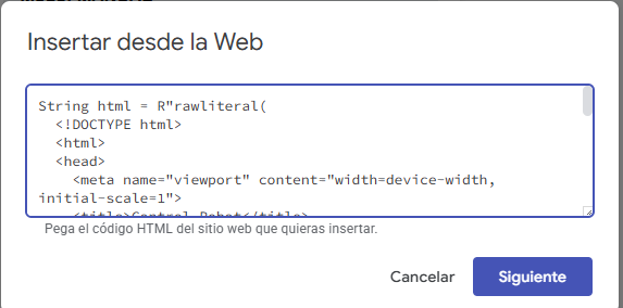
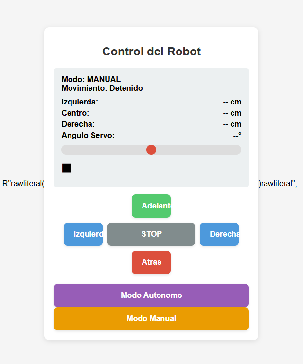
we will have a preview of the interface
6.-Using the Arduino IDE
To perform the readings and functional tests, I used the Arduino IDE with the XIAO ESP32-C3.
Motor Control Code (ESP32-C3 + L298N + BLE)
#include <BLEDevice.h>
#include <BLEUtils.h>
#include <BLEServer.h>

// Pin definition for the L298N controller
#define IN1 6  // Motor 1 - Direction
#define IN2 7  // Motor 1 - Direction
#define IN3 8  // Motor 2 - Direction
#define IN4 9  // Motor 2 - Direction
#define ENA 5  // Motor 1 - Speed (PWM)
#define ENB 10 // Motor 2 - Speed (PWM)

// Bluetooth Low Energy (BLE) Setup
BLEServer *pServer = NULL;
BLECharacteristic *pCharacteristic = NULL;

#define SERVICE_UUID "4fafc201-1fb5-459e-8fcc-c5c9c331914b"
#define CHARACTERISTIC_UUID "beb5483e-36e1-4688-b7f5-ea07361b26a8"

void setup() {
    Serial.begin(115200);

    // Output pin configuration for the motor
    pinMode(IN1, OUTPUT);
    pinMode(IN2, OUTPUT);
    pinMode(IN3, OUTPUT);
    pinMode(IN4, OUTPUT);
    pinMode(ENA, OUTPUT);
    pinMode(ENB, OUTPUT);

    Stop(); // Ensure the motors are stopped at startup

    // BLE module configuration
    BLEDevice::init("Rover ESP32C3");
    pServer = BLEDevice::createServer();
    BLEService *pService = pServer->createService(SERVICE_UUID);
    pCharacteristic = pService->createCharacteristic(
                        CHARACTERISTIC_UUID,
                        BLECharacteristic::PROPERTY_READ |
                        BLECharacteristic::PROPERTY_WRITE);
    pService->start();
    BLEAdvertising *pAdvertising = BLEDevice::getAdvertising();
    pAdvertising->addServiceUUID(SERVICE_UUID);
    pAdvertising->start();
}

void loop() {
    // Check if a command has been received via BLE
    if (pCharacteristic->getValue().length() > 0) {
        String command = pCharacteristic->getValue().c_str();
        Serial.println("Received: " + command);

        // Interpret the received command
        if (command == "F") forward();  // Move forward
        else if (command == "B") backward(); // Move backward
        else if (command == "L") left(); // Turn left
        else if (command == "R") right(); // Turn right
        else if (command == "S") Stop(); // Stop motors
    }
}

// Move rover forward
void forward() {
    digitalWrite(IN1, HIGH);
    digitalWrite(IN2, LOW);
    digitalWrite(IN3, HIGH);
    digitalWrite(IN4, LOW);
    analogWrite(ENA, 200); // PWM speed control
    analogWrite(ENB, 200);
}

// Move rover backward
void backward() {
    digitalWrite(IN1, LOW);
    digitalWrite(IN2, HIGH);
    digitalWrite(IN3, LOW);
    digitalWrite(IN4, HIGH);
    analogWrite(ENA, 200);
    analogWrite(ENB, 200);
}

// Turn left
void left() {
    digitalWrite(IN1, LOW);
    digitalWrite(IN2, HIGH);
    digitalWrite(IN3, HIGH);
    digitalWrite(IN4, LOW);
}

// Turn right
void right() {
    digitalWrite(IN1, HIGH);
    digitalWrite(IN2, LOW);
    digitalWrite(IN3, LOW);
    digitalWrite(IN4, HIGH);
}

// Stop motors
void Stop() {
    digitalWrite(IN1, LOW);
    digitalWrite(IN2, LOW);
    digitalWrite(IN3, LOW);
    digitalWrite(IN4, LOW);
}
7.-Results
Conclusions:
This week has been crucial in making significant progress on my final project. As I enter the final phase, I've realized we're incorporating more processes and techniques than I initially anticipated. It's been both a challenging and rewarding experience to see how the project has evolved and taken shape over time.