Week 7
Computer-Controlled Machining
Week Overview
This week, I planned, designed, and built a full-scale plywood furniture unit from start to finish. I began with hand-drawn sketches to nail down the overall dimensions and joint clearances, then recreated each panel in Fusion 360—extruding them to 18 mm thickness, adding dog-bone reliefs and tabs for clean CNC cuts. After defining the stock size, toolpaths, heights, and ramp entries, I ran simulations, post-processed the G-code, and loaded it onto the large-format CNC. Finally, I sanded all the pieces and assembled the complete unit.
Group Assignment Overview
During this stage, the team first completed the lab’s mandatory safety training to ensure proper handling of tools and materials. We then performed a series of machine validation tests—checking spindle run‐out, verifying axis alignment, and designing fixtures to secure the stock reliably. With the machine prepared, we experimented with different cutting parameters (speeds, feeds and step-overs) on representative materials and toolpaths, refining each setting until the cuts met our quality standards. All procedures, observations and test results have been documented on the group work page, while each member reflects on the lessons learned and improvements discovered on their individual pages.
Individual Assignment
Project Overview
For the Week 7 individual assignment, I designed, milled and assembled a full-size furniture unit out of 18 mm plywood. The process began with hand-drawn sketches to define form and dimensions, followed by detailed CAD modeling in Fusion 360. I then generated G-code directly in Fusion for a large-format CNC cutter, executed the machining, performed surface finishing, and finally assembled the parts into the final piece.
Concept Sketch & Planning
The project started with hand-drawn sketches in a notebook, showing side and front views of the furniture unit with key dimensions: 105 cm height, 50 cm width and 18 mm material thickness. These sketches helped define the overall form, joints and clearances (2 cm gaps) before moving into CAD.
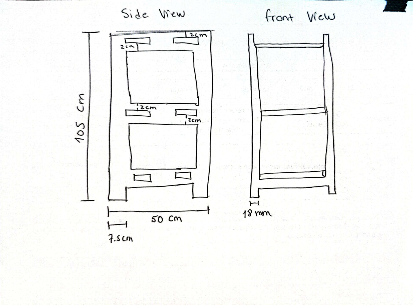
Hand-drawn side and front views with all critical measurements annotated.
CAD Design in Fusion 360
Using Fusion 360, the rough sketches were translated into precise 3D models. I set the material thickness parameter to 18 mm.
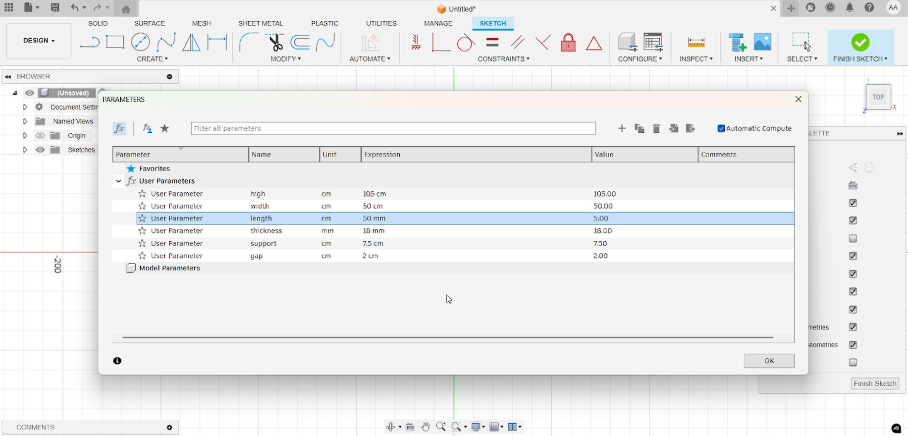
Parameters of design.
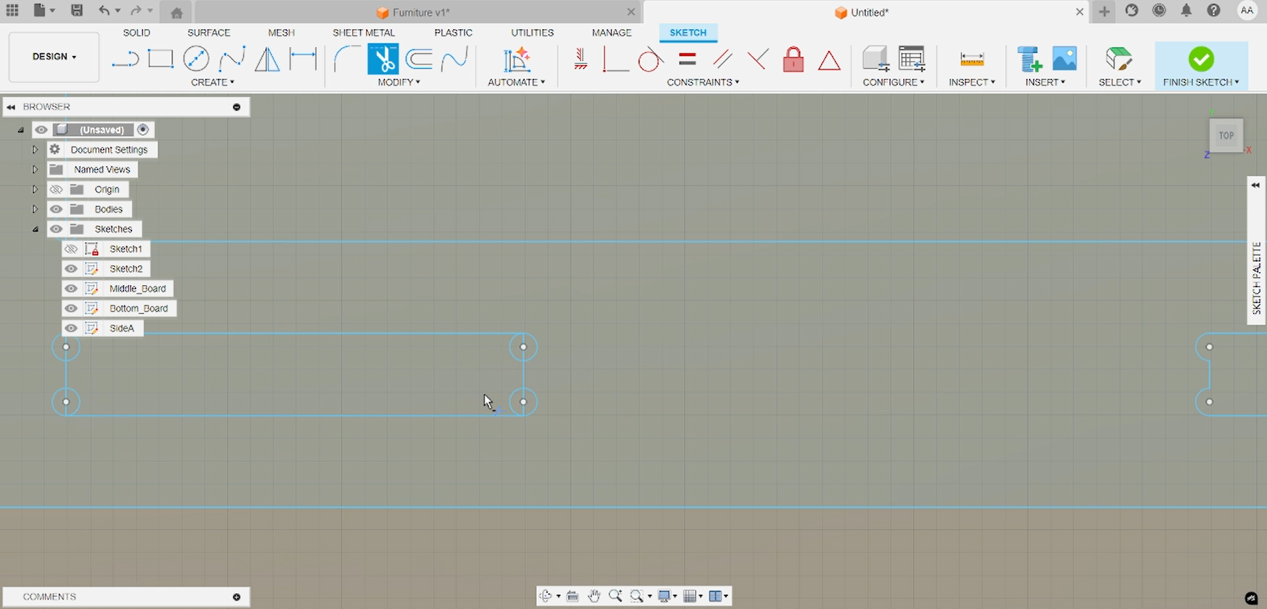
Defining the Side Panel in Fusion 360
The first CAD step was modeling a single side panel of the furniture. In this sketch, I laid out all critical dimensions: the total height (1 050 mm), the material thickness (18 mm), and the precise positions for square-cut joints with 20 mm clearances between them. Ensuring correct joint spacing upfront prevents assembly issues later.
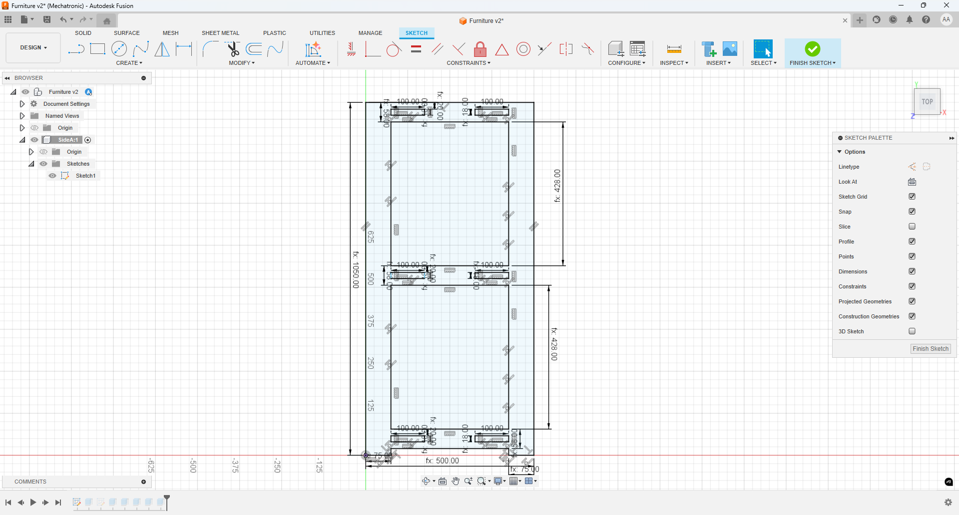
Fusion 360 sketch showing side panel dimensions, joint locations and 20 mm clearances.
Extruding the Side Panel
The next step was to extrude the 2D sketch into a 3D solid, using the exact sheet thickness of 18 mm. This creates a realistic model of the panel that matches the physical plywood sheet, ready for nesting and CAM toolpath generation.
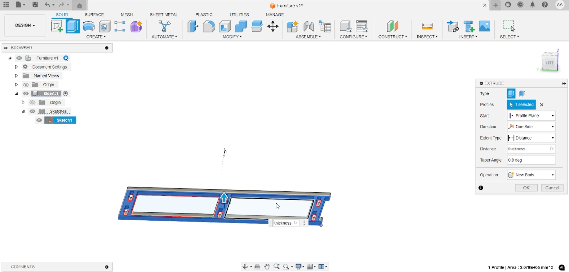
Extruded solid panel in Fusion 360, thickness set to 18 mm to match material.
Creating the Opposite Side Panel
To model the second side (Panel B), I created a new component in Fusion 360 and started a fresh sketch on its XY plane. Using the Project command, I referenced the edges and joint locations from Panel A’s sketch. After projecting these key features, I extruded the sketch to 18 mm, producing a perfectly mirrored counterpart ready for CAM nesting.
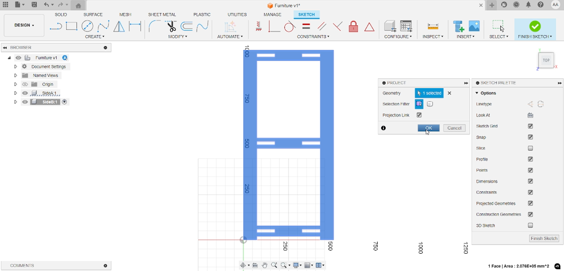
Projecting Panel A geometry into Panel B’s sketch.
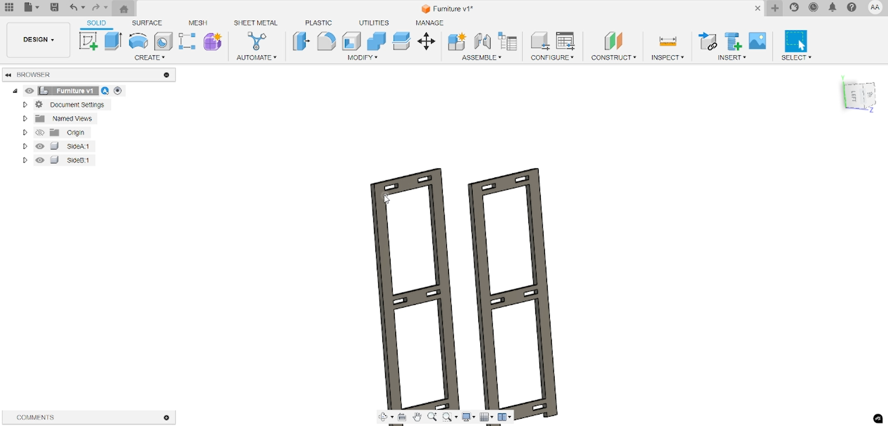
Extruding Panel B to the same 18 mm thickness.
Creating Joint Slots
A construction plane was placed at the mid-thickness of the panel to align with the joint edges. On this plane, a rectangle was sketched and extruded through the full 18 mm thickness to form the slot for the finger joint.
Midplane joint slot sketch and extrusion in Fusion 360.
Modeling Middle and Lower Shelves
Next I created separate components for the middle and lower shelves in Fusion 360, positioning them between Side A and Side B. At this stage the flat parts look complete, but to ensure the shelves lock into the sides and support the structure, we need to add tabs where they intersect the panels. These tabs will fit into the side panel slots and keep the unit standing securely.
Fusion 360 view of middle and lower shelf outlines before adding registration tabs.
Creating Registration Tabs with Combine
To generate precise registration tabs where the shelves meet the side panels, I used Fusion 360’s Combine tool. For each shelf component, I set the shelf as the Target Body and the corresponding side panel as the Tool Body, chose the Cut operation, and enabled Keep Tool. This created matching tabs on the shelves that fit perfectly into the side panel slots.
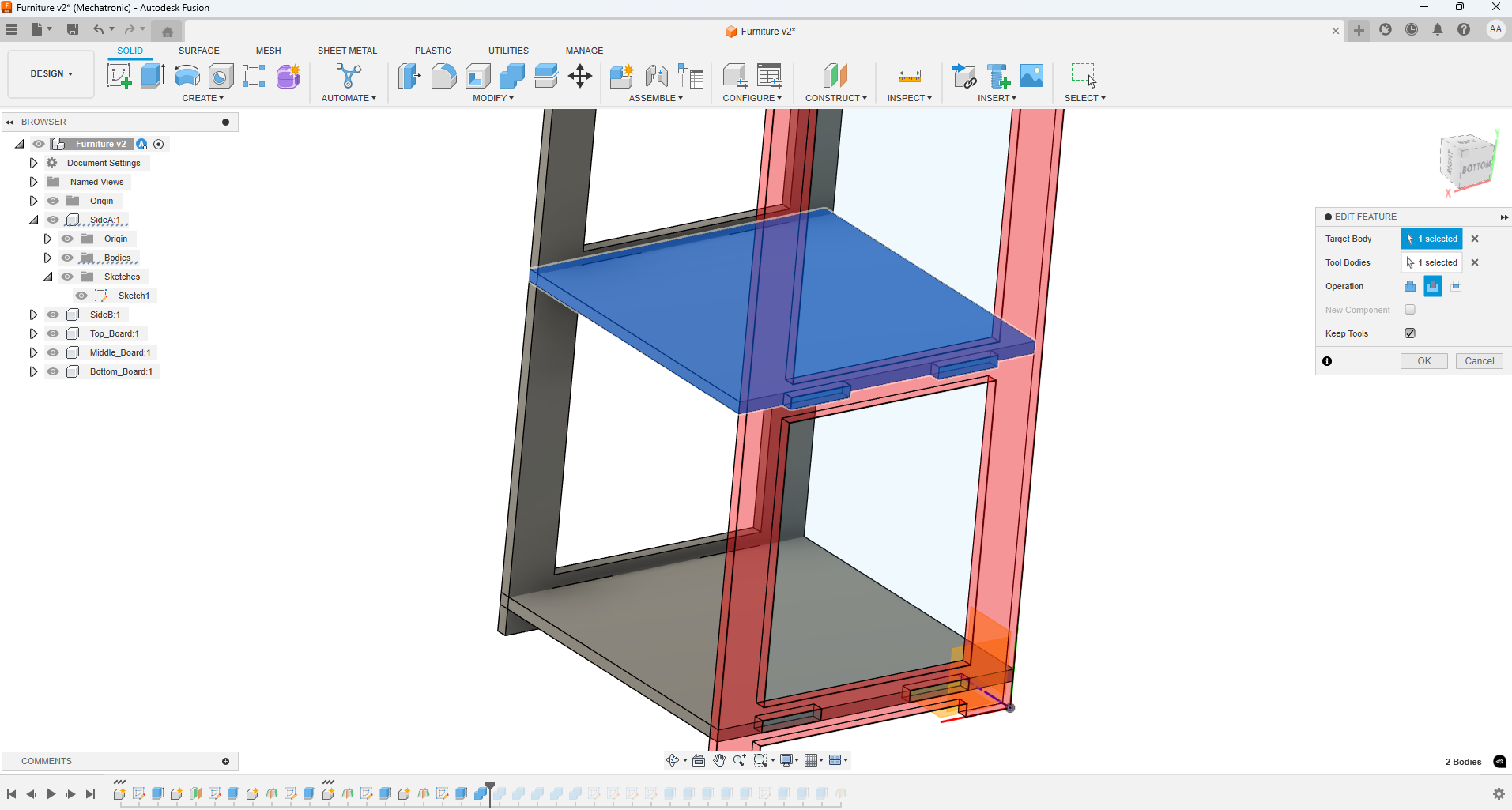
Result of the Combine→Cut operation with “Keep Tool” enabled, producing registration tabs on the shelves.
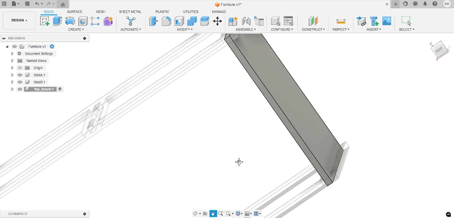
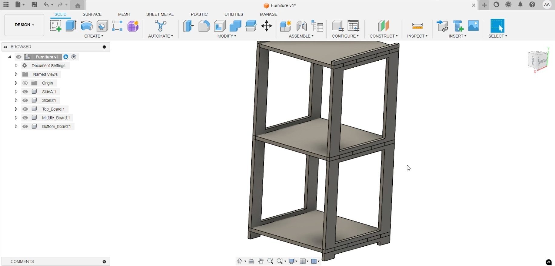
Final Shelf-Panel Integration
The final result shows each shelf component precisely intersected with Side A and Side B only at the joint locations. All panels and shelves fit together snugly, and the assembled furniture meets the original design dimensions.
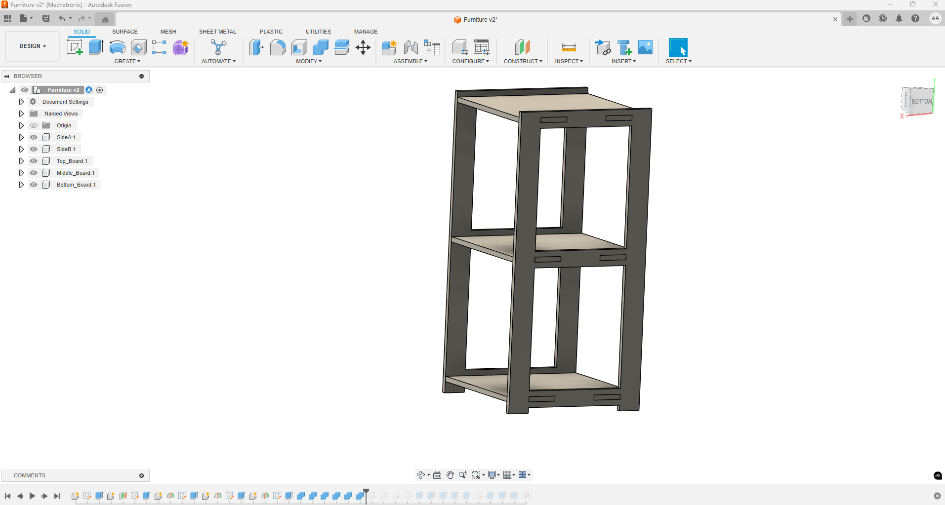
Fusion 360 final assembly view with shelves locked into side panel slots.
CAM Setup & G-code Generation
The first step was to define the stock plate matching the lab table dimensions: 120 cm width × 240 cm length. I set this as my stock in Fusion 360.
Next, I chose the lower-left corner of the stock as the origin (0,0,0) reference point. Using the Project tool, I projected each furniture part outline onto this base plate to position them for cutting.
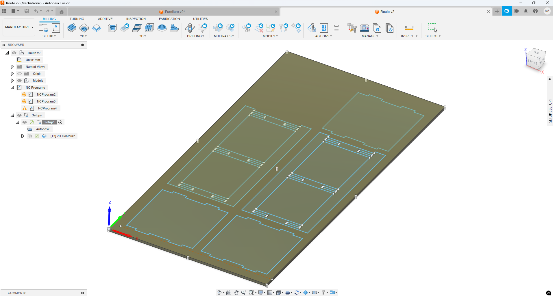
Stock setup (120×240 cm) with all panel outlines projected at the lower-left origin.
Tool Definition & Configuration for Contour Operation
Since the only machining operation needed was a 2D contour, I created and configured a single flat endmill tool in Fusion 360. Below are the key settings I used:
- Tool Type: Flat end mill
- Diameter: 6 mm
- Shaft diameter: 6 mm
- Overall length: 51 mm
- Flute length: 21 mm
- Material: Carbide
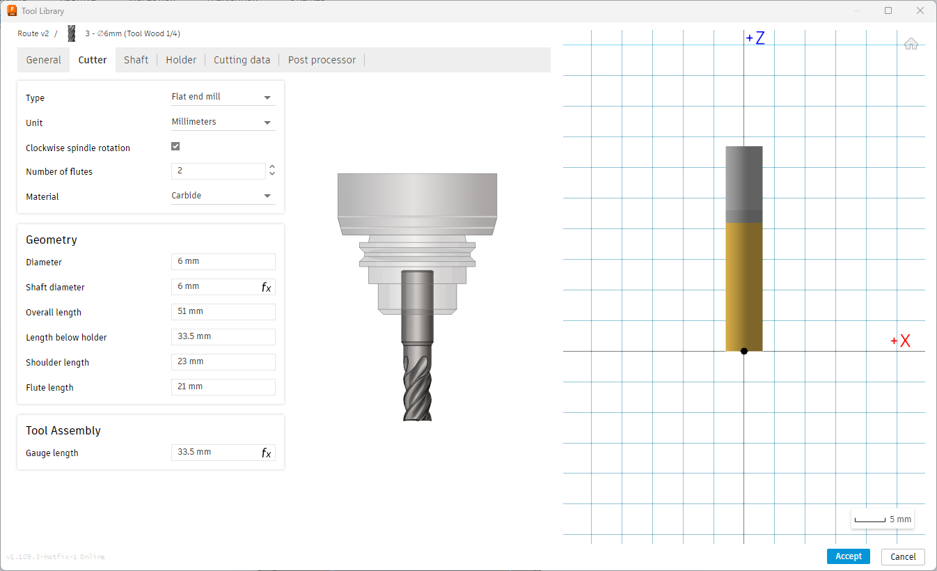
Cutter tab: flute count 2, carbide material, overall length 51 mm, flute length 21 mm.
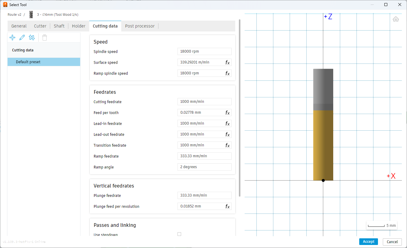
Cutting Data tab: spindle 18 000 rpm, feedrate 1 000 mm/min, plunge 333 mm/min.
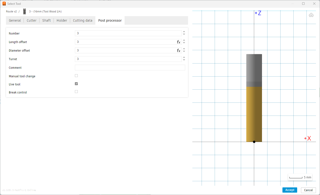
Post-processor tab: tool number 3, length offset 3, diameter offset 3, live tool enabled.
Machine Settings: Feed Rate and Spindle Speed
For this CNC job, I configured the spindle speed to 19,000 rpm and set the cutting feed rate to 2,500 mm/min. The surface speed was configured at 358.142 m/min. Additional parameters included a ramp spindle speed of 19,000 rpm, ramp feedrate of 833.333 mm/min, and plunge feedrate of 833.333 mm/min. These values were selected to optimize the process with a 6 mm flat wood router bit, balancing efficiency and surface quality.
- Spindle Speed: 19,000 rpm
- Cutting Feed Rate: 2,500 mm/min
- Surface Speed: 358.142 m/min
- Feed per Tooth: 0.0657895 mm
- Lead-In/Lead-Out/Transition Feedrate: 2,500 mm/min
- Ramp Feedrate: 833.333 mm/min
- Plunge Feedrate: 833.333 mm/min
- Plunge Feed per Revolution: 0.0438596 mm
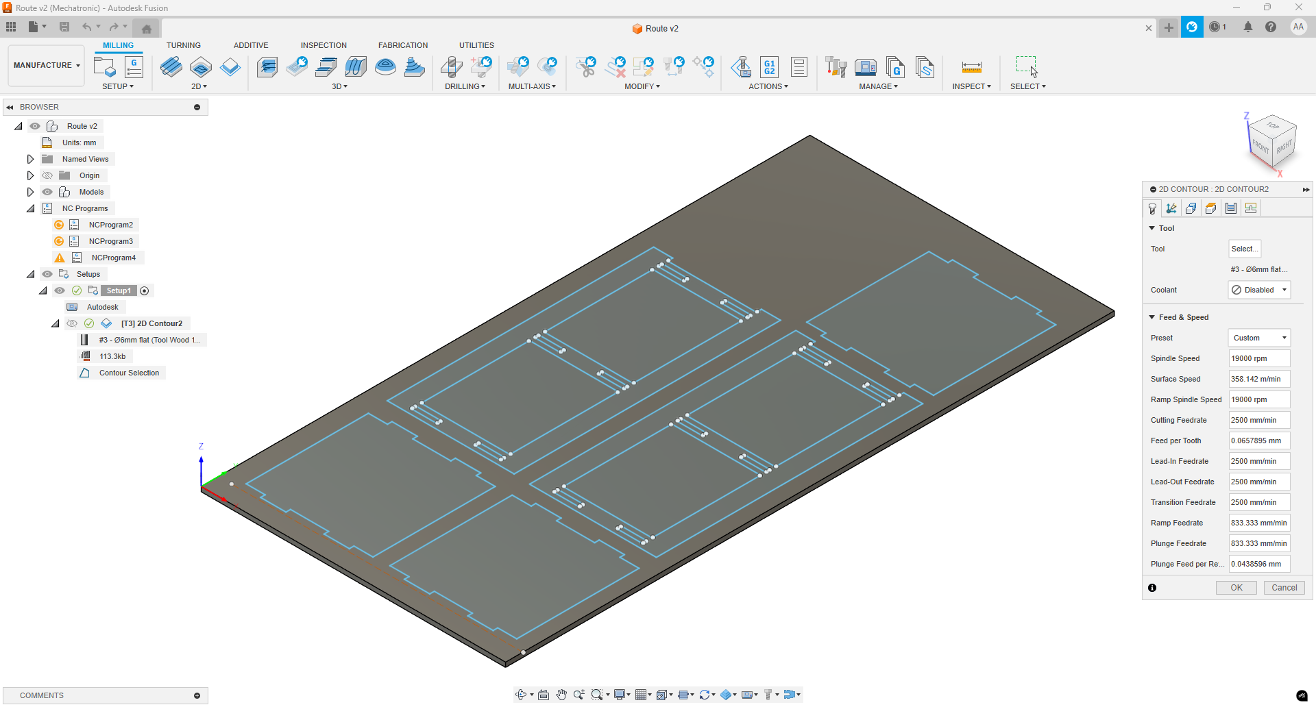
CAM software screenshot showing spindle speed, feed rates, and other machining parameters for this operation.
Contour Operation & Tab Configuration
After selecting the 6 mm flat endmill in the Geometry tab, I picked all projected outlines on the stock for the contour cut. To ensure the parts remain held in place during machining, I enabled Tabs with the following settings:
- Tab width: 6 mm
- Tab height: 3 mm
- Tabs per contour: 4
These tabs keep each piece anchored to the spoilboard until final removal, preventing movement or vibration as the router passes.
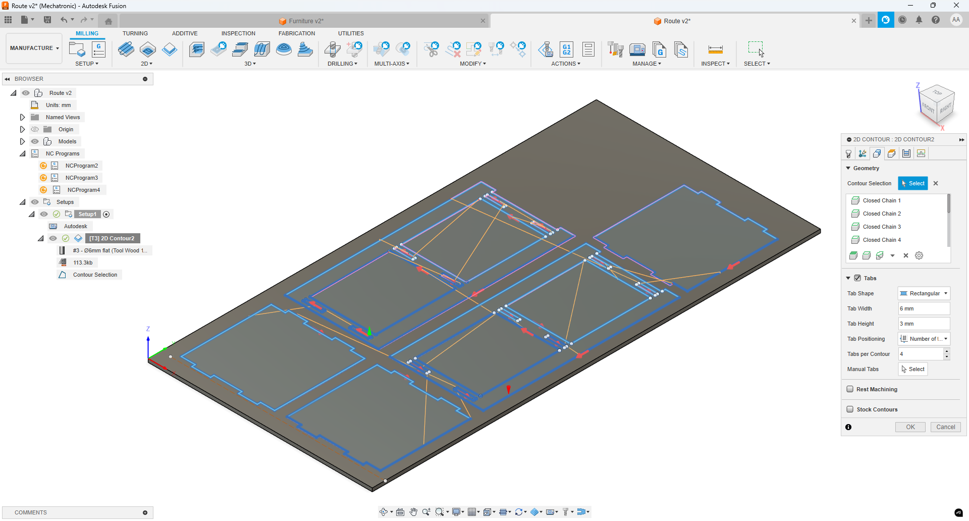
Contour toolpath preview showing four 6 mm × 3 mm tabs per outline.
Heights & Clearance Settings
In the Heights tab of the contour operation, I adjusted the following clearance and bottom heights to ensure the cutter fully penetrates the 18 mm stock:
- Clearance Height: Set above the stock top to avoid collisions during rapid moves.
- Pocket Bottom Height: Lowered slightly below the stock bottom (–0.4 mm) so the tool cuts completely through the plywood.
These settings guarantee a clean through-cut while keeping the tool safe during entry and exit.
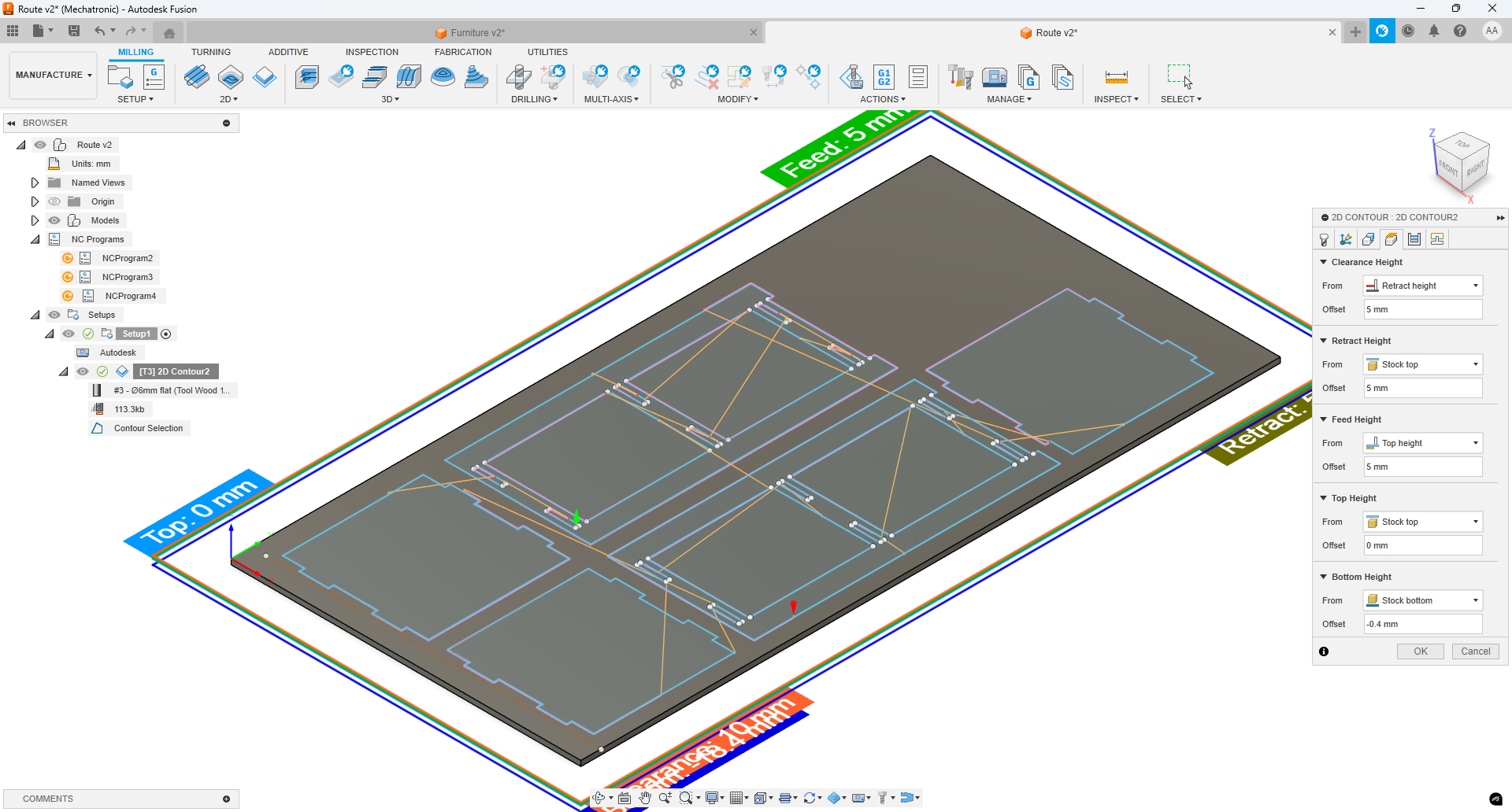
Heights tab configuration with Clearance at 5 mm above the stock and Bottom Height at –1 mm.
Linking & Ramp Entry Settings
In the Linking tab, I enabled Ramp Entry to protect the cutter during engagement. The settings used were:
- Ramp Angle: 2°
- Maximum Ramp Step: 5 mm
- Ramp Clearance Height: 1 mm
These parameters ensure the tool enters the material gradually at a shallow angle, reducing stress on the endmill and improving cut quality.
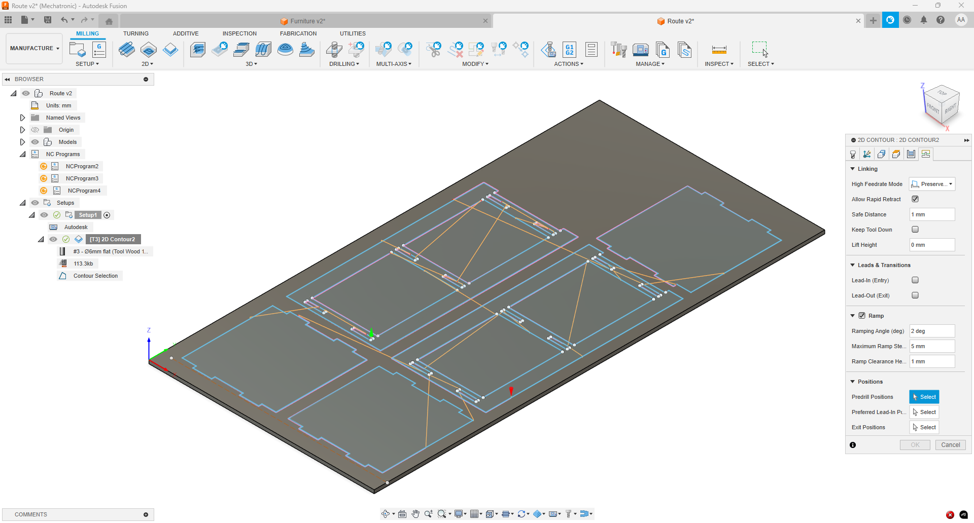
Linking tab preview showing ramp entry enabled with a 2° angle and 5 mm step.
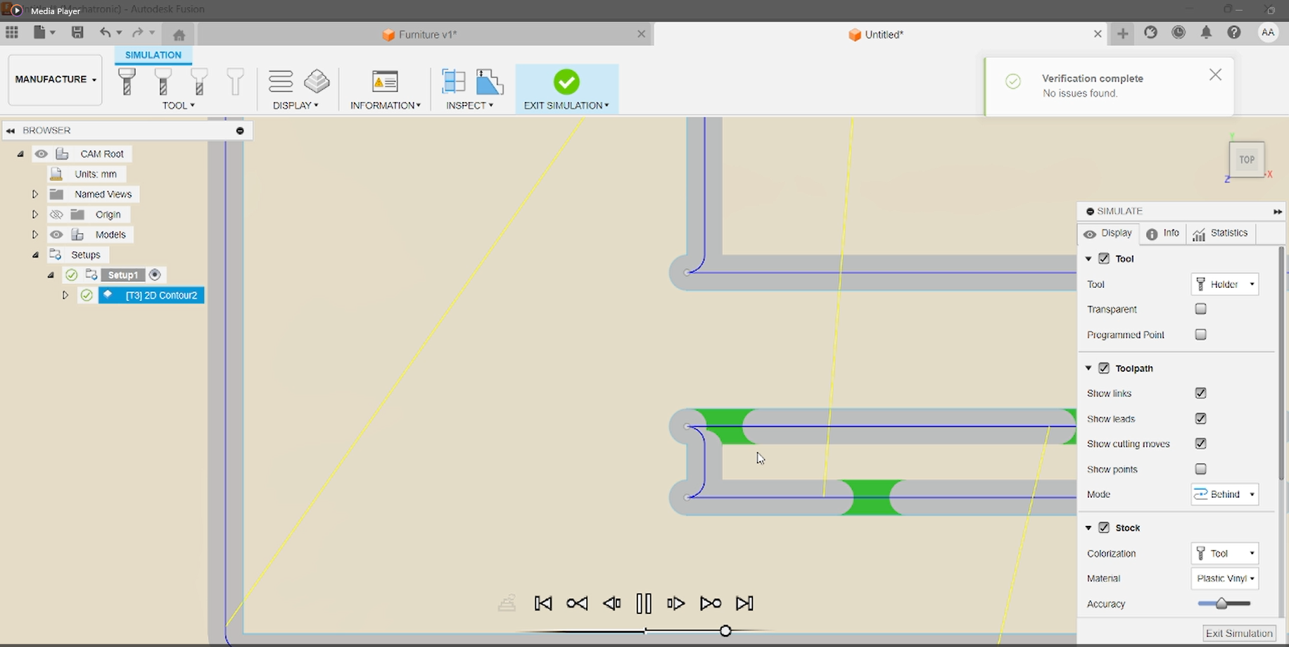
Simulation of Toolpaths
To verify the contour toolpaths and ensure there were no collisions or errors, I clicked on Actions → Simulate in the Manufacture workspace. This simulation allowed me to preview the cutter’s movement, confirm proper tab placement, and validate full-depth cuts before exporting G-code.
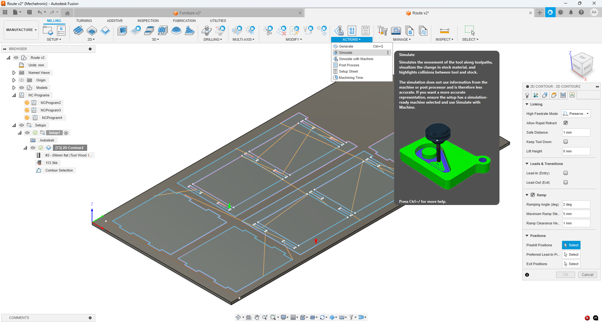
Simulation preview showing the contour operation with tab support and full-depth cuts.
Adding Dog‐Bone Reliefs
During the simulation, I noticed that the 6 mm cutter could not produce perfectly square internal corners. My colleague Michael Torres suggested adding “dog‐bone” reliefs at each internal corner. These small semicircular cutouts allow the tool to fully clear the corner, ensuring a snug fit when assembled.
Sketching & Cutting Dog‐Bone Reliefs
To create the dog‐bone reliefs, I sketched a 6 mm-diameter circle centered on each internal corner point (using the two-point circle tool). After placing all four circles, I used the Trim tool to remove the unnecessary sketch lines inside the circles, leaving only the semicircular cutouts at each corner.
Two-point circles of 6 mm diameter drawn at each corner, then trimmed to form dog-bone reliefs.
Re-Simulating with Dog‐Bone Reliefs
After adding the dog-bone cutouts, I re-ran the simulation to verify the result. The updated contour now produces much sharper internal corners, as the reliefs allow the 6 mm cutter to clear the joint fully. One drawback is that the semicircular shape remains visible in the final part, requiring a light hand-sanding to blend the relief into the corner.
Simulation overlay showing crisp corners with dog-bone reliefs; note the semicircle remains in the final profile.
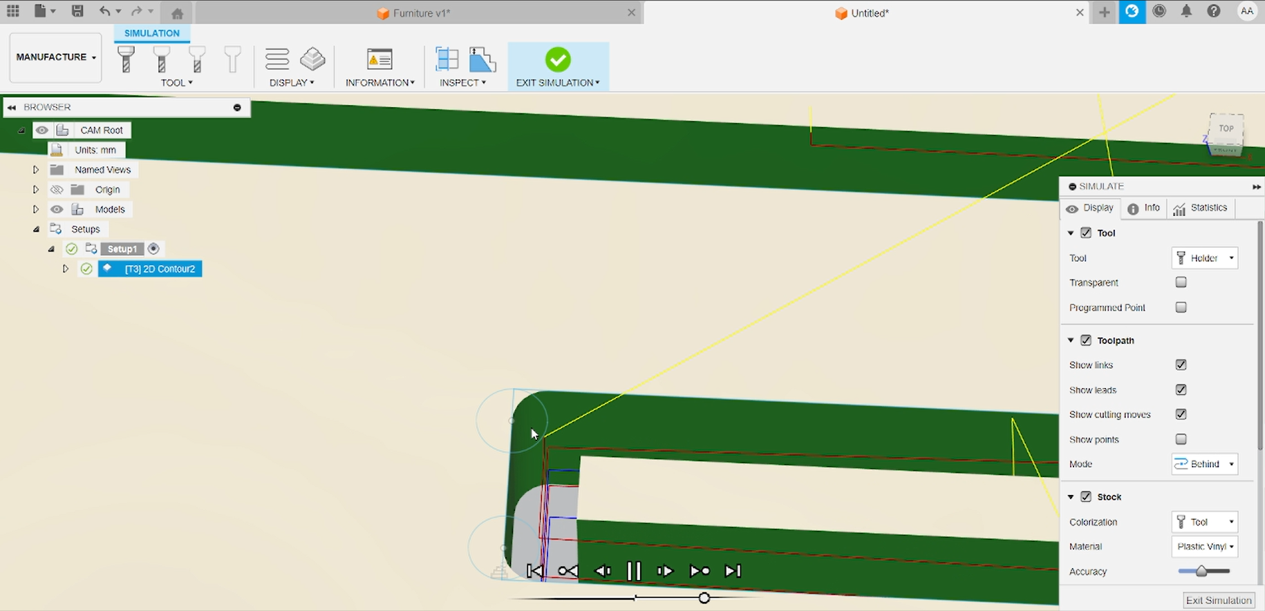
Cutting Simulation Video
Below is a video demonstrating the CNC simulation of the contour operation with dog-bone reliefs and tabs in place.
Fusion 360 simulation playback showing the toolpath cutting through the stock, including dog-bone corners and tabs.
Post Process & G-code Export
Once I was satisfied with the simulation, I proceeded to generate the actual G-code. In the Manufacture workspace, I selected Actions → Post Process on the setup item. I chose the post-processor and set the output file name.
The resulting .nc file was copied to a USB drive and is now ready to be loaded into the CNC controller for cutting.
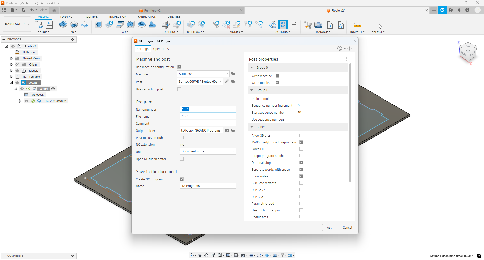
Fusion 360 Post Process.
CNC Machining Setup & Fixturing
With the help of my students Santiago Aldana, Juan Diego Romero, and classmates Michael Torres and Jhonatan Cortés, we configured the CNC machine to suit our 18 mm plywood stock. This included setting the homing position at the front-left corner, adjusting the Z-offset and clearance heights to accommodate tool length, and defining the X-Y work area to exactly match the sheet dimensions on the spoilboard.
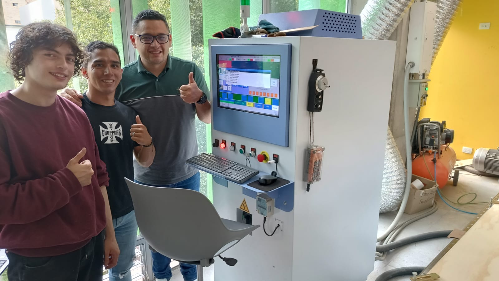
Initial CNC configuration: homing point, Z-offset adjustment, and work area boundaries.
Configured Reference Points & Ready to Cut
Here you can see the CNC machine with all reference points and offsets properly configured. The homing position, Z-offset, and work area boundaries have been set, and the G-code file furniture_week7.ngc is loaded. The machine is now ready to start the cutting process.
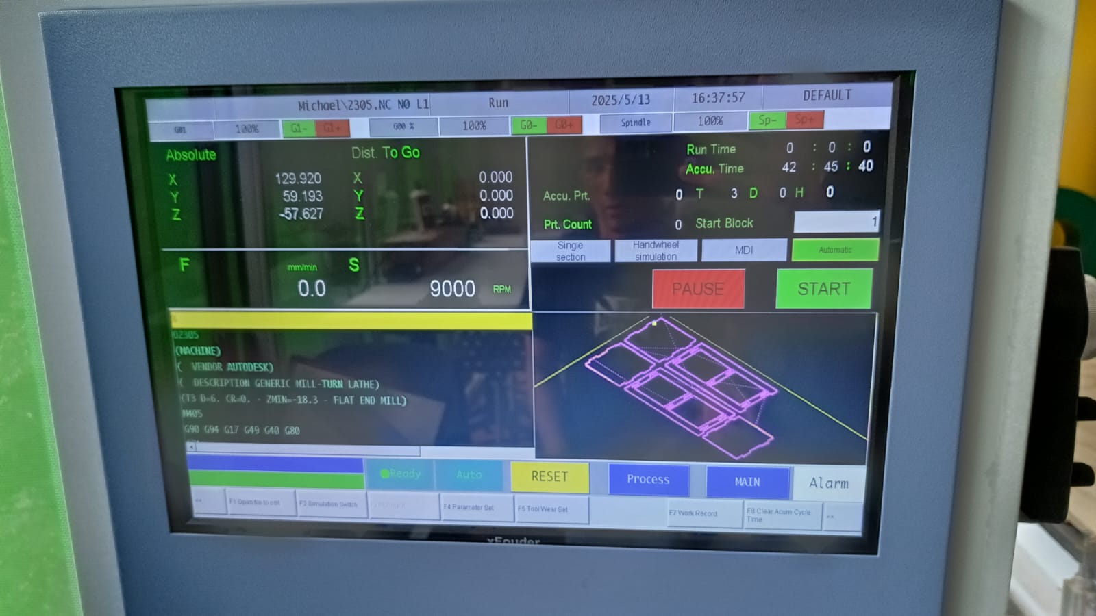
CNC spindle at home position with stock secured and G-code loaded, ready for the contour operation.
Machine Configuration
Below is a photo showing the CNC machine fully configured and ready for operation with the spoilboard secured.
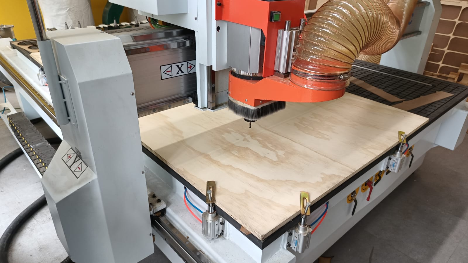
CNC machine setup in the workshop before starting the cutting process.
Cutting Operation Demonstration
The following video shows the CNC machine in action, cutting the plywood panels according to the generated G-code.
Real-time footage of the CNC executing the contour cuts, with tabs and dog-bone reliefs in place.
Post-Cut Parts & Preliminary Finishing
Once the CNC cutting completed, all furniture panels and shelf components were removed from the spoilboard. Before assembly, each part was carefully sanded to remove tabs, smooth edges, and correct any minor imperfections from the machining process.
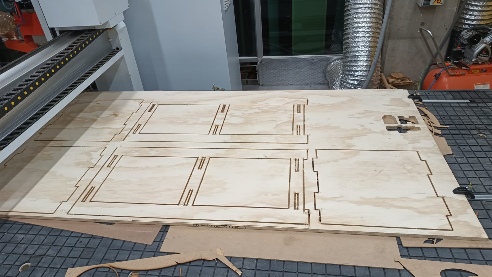
All cut panels lined up—ready for detailed sanding to refine joints and surfaces.
Final Assembly & Conclusion
After cleaning and sanding each part, I carefully assembled the furniture panels and shelves. Despite the initial apprehension about CNC setup and potential errors, the project came together successfully thanks to meticulous planning and teamwork. This marks the completion of Week 7’s individual assignment, demonstrating the full workflow from concept sketch to finished assembly.
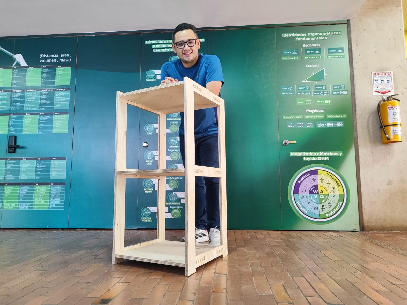
Photograph of the completed furniture unit, assembled and ready for use.
Detail: Dog‐Bone Relief Visibility
In the photo below, you can see how the dog-bone reliefs remain visible as part of the assembled structure. While they allow the cutter to clear the joint, a cleaner aesthetic could be achieved by using mortise-and-tenon or other joint techniques.
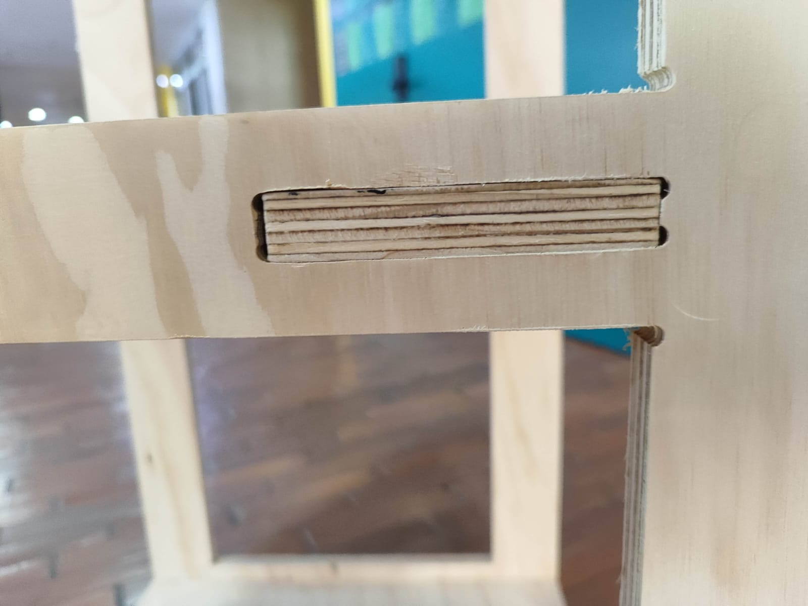
Dog-bone semicircles visible at internal corners; consider alternative joint designs for improved aesthetics.
Final Result
The final piece stands complete, showcasing the full assembly of panels and shelves with all joints and reliefs in place. It meets the original design dimensions and functions as intended.
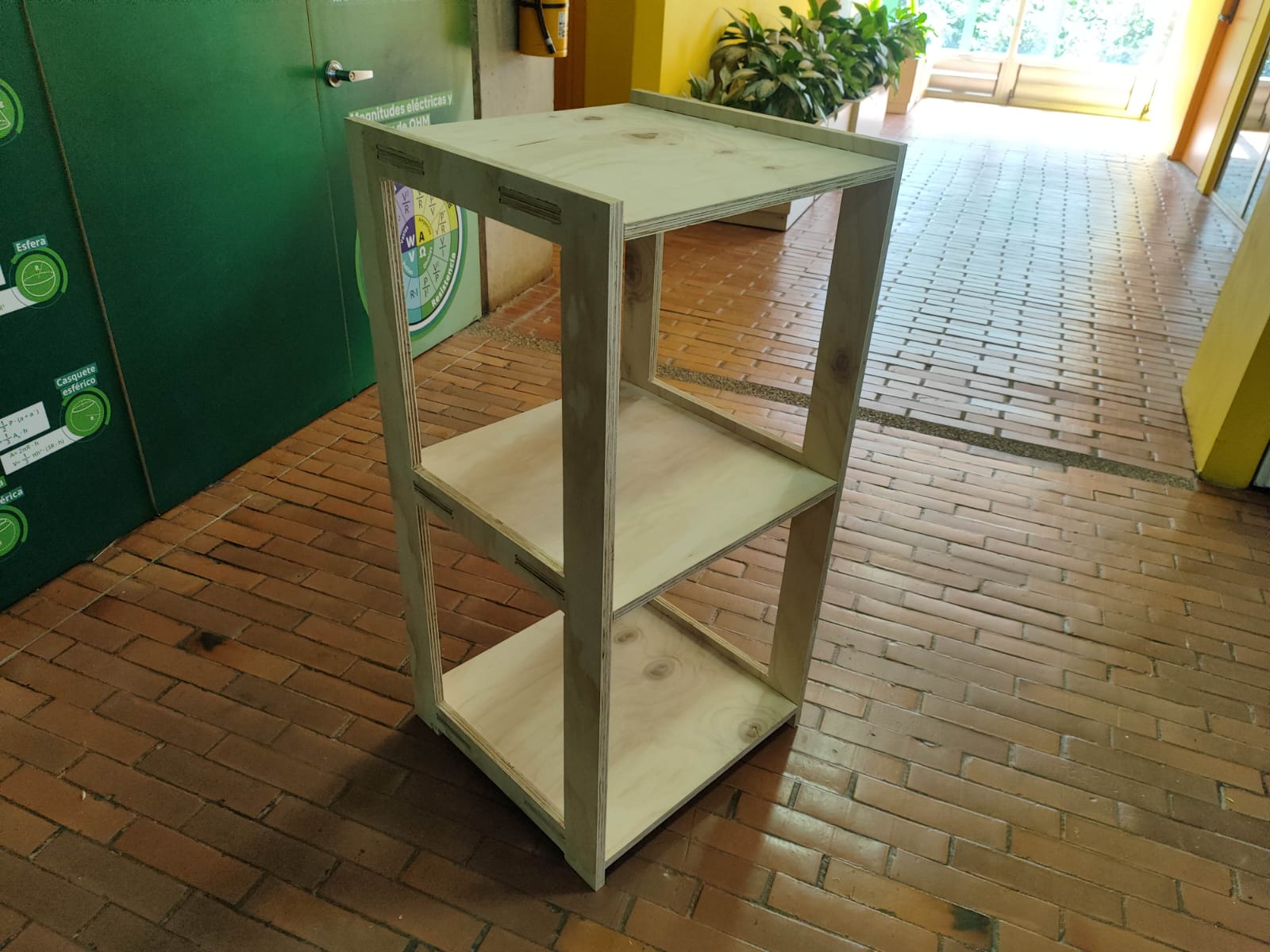
Overview of the finished furniture, fully assembled and ready for use.
Conclusions & Reflections
- Designing the furniture in Fusion 360 reinforced the importance of precise dimensioning and joint clearance planning.
- Configuring CAM toolpaths—with tabs, dog-bone reliefs, and ramp entries—highlighted how machining parameters directly impact fit and finish.
- Simulating before cutting saved material and time by catching corner-clearance issues early.
- Hands-on CNC setup and fixturing, alongside classmates, built confidence in machine operation and error mitigation.
- Visible dog-bone reliefs worked functionally but suggest exploring alternative joints for cleaner aesthetics in future projects.
- Overall, this week’s workflow—from concept sketch to final assembly—illustrated the full digital fabrication cycle and its practical challenges.
Downloads
You can download the key project files below to reproduce or review each stage of the workflow:
- Fusion 360 Archive – full CAD model with all components and joints. (.f3d)
- Fusion 360 Archive – full CAD model with all components and joints. (.obj)
- Fusion 360 Cut Archive – full CAD cut model(.f3d)
- Post-Process file configuration