Week 5
3D Scanning and Printing
Introduction
This week focused on exploring additive manufacturing through 3D printing and object scanning. The goal was to design and fabricate a 3D object that could not be made subtractively, perform scanner calibration, and process a scanned model. Tools such as Fusion 360, Orca Slicer, and the Revopoint 3D scanner were used to complete the assignments.
Group Assignment
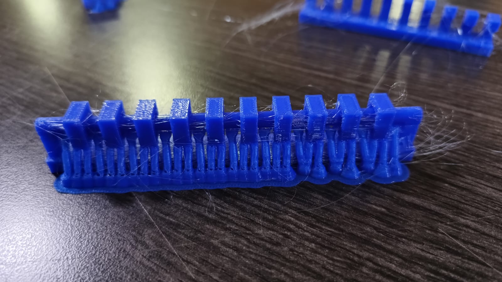
As part of the group assignment, we conducted calibration tests using various STL files to characterize the print quality of our Ender 3 V3 SE printer with PLA material. These files include tests for overhang, bridging, clearance, and angle tolerance. For example, here are the reference images of the different STL files.
The first step was to meet as a group to establish the work strategy and exchange experiences regarding the use of 3D printers.
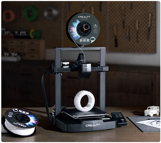
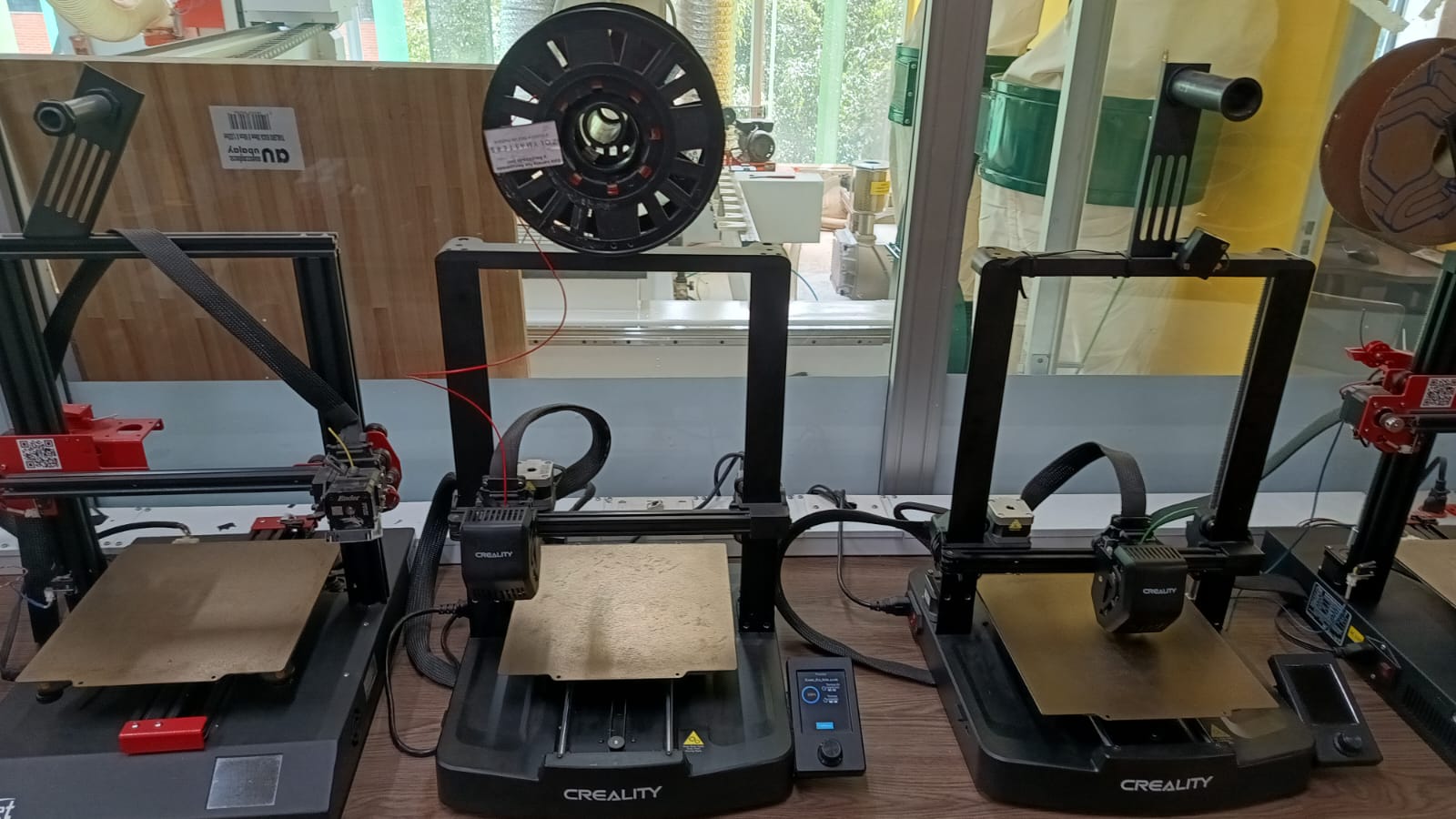
The printer I used for this assigment was the ENDER 3 VE SE which is available at the fablab of Ean University in Bogota, Colombia.
| Ender 3 V3 SE - Key Specifications | |
|---|---|
| Printing Technology | FDM |
| Build Volume | 220×220×250 mm |
| Nozzle Temperature | ≤260 °C |
| Bed Temperature | ≤100 °C |
| Typical Printing Speed | 180 mm/s |
| Max Printing Speed | 250 mm/s |
| Acceleration | 2500 mm/s² |
| Layer Height | 0.1–0.35 mm |
| Supported Filaments | PLA, PETG, TPU(95A) |
| Extruder Type | Sprite Direct Extruder |
| Leveling Mode | Auto Leveling |
| File Formats | STL, OBJ, 3MF, AMF |
| Slicing Software | Creality Print, Cura 5.0+, Simplify3D |
| Display | 3.2" Color Knob Screen |
| File Transfer | SD Card |
3D Printing Configuration
To manufacture the models, I used a Creality Ender 3 V3 SE with PLA filament. The slicing was done using Orca Slicer, applying standard parameters suitable for a calibration and functional test model. The printing setup ensured adequate quality and adhesion for the selected material and geometry.
| Parameter | Value |
|---|---|
| Printer | Creality Ender 3 V3 SE |
| Material | PLA |
| Slicing Software | Orca Slicer |
| Models Used | Clearance Test, Overhang Test, Bridging Test, Angle Test |
| Layer Resolution | 0.2 mm |
| Infill | 15% |
| Extruder Temperature | 200°C |
| Bed Temperature | 60°C |
3D Print Test Results
During this phase, several test prints were performed to evaluate the capabilities and calibration of the Ender 3 V3 SE printer using PLA and ORCA Slicer. The tests included clearance, overhangs, bridges, and angles. The models revealed key insights about print precision, support needs, and nozzle behavior under different configurations.
🧪 3D Printing Test Results and Observations
To evaluate the performance of the Ender 3 V3 SE using PLA, I printed several standard calibration models designed to test clearance, overhangs, bridging, and unsupported angles. These tests helped me better understand the printer’s capabilities and fine-tune the slicing settings in ORCA Slicer accordingly.
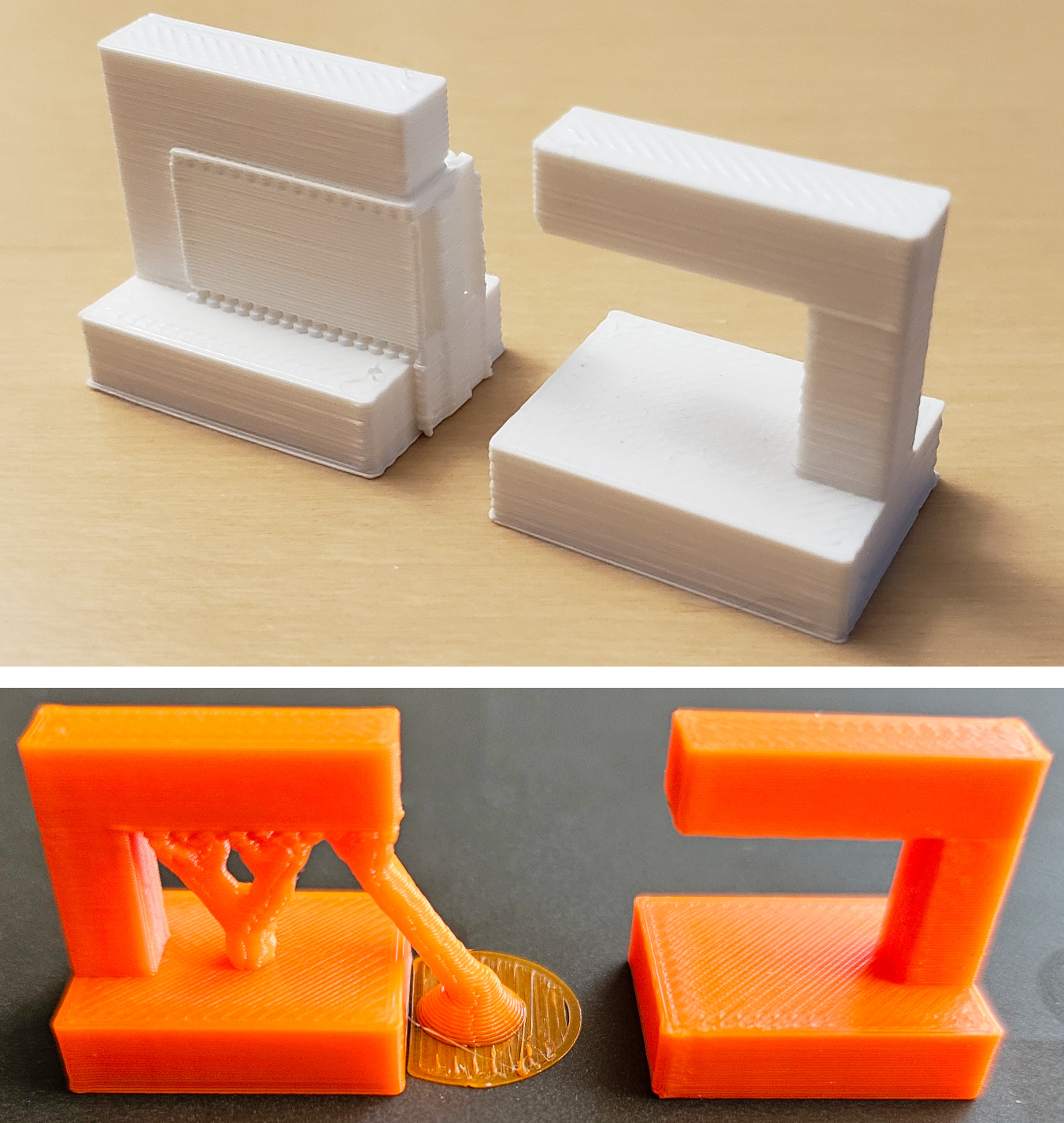
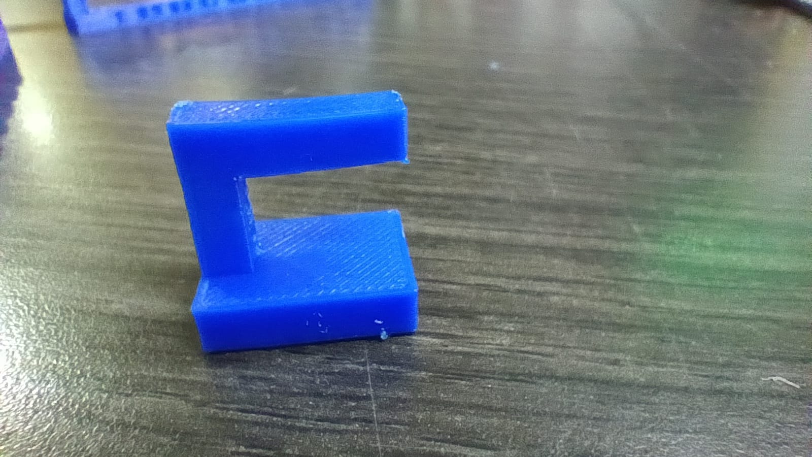
🧩 Clearance Test
The clearance test showed that gaps under 0.4 mm tend to fuse together, indicating slight over-extrusion or the need for better retraction settings. From 0.4 mm and above, the parts behaved as expected and could be separated easily.
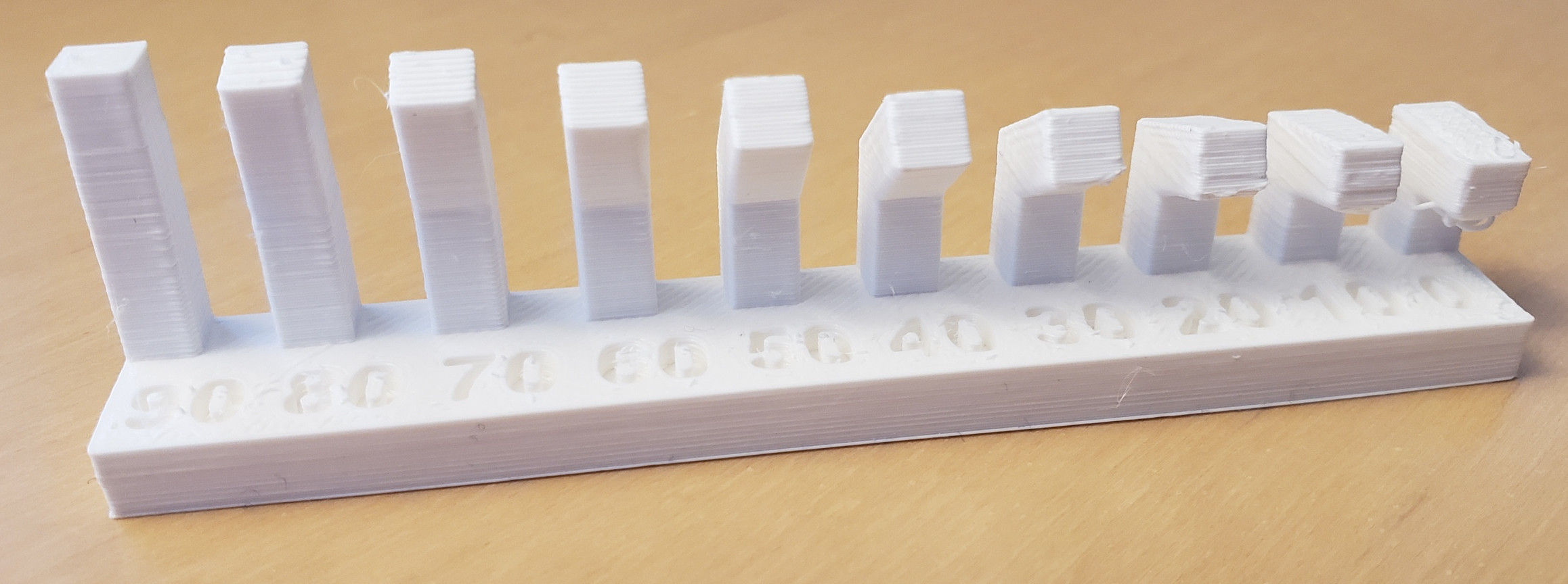
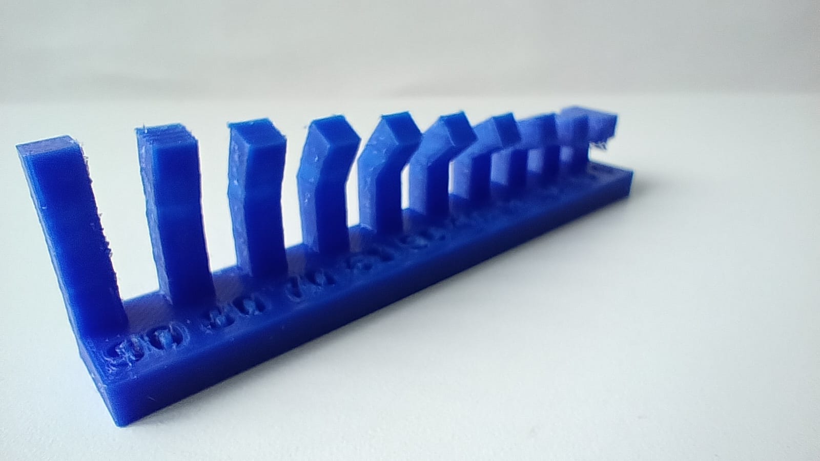
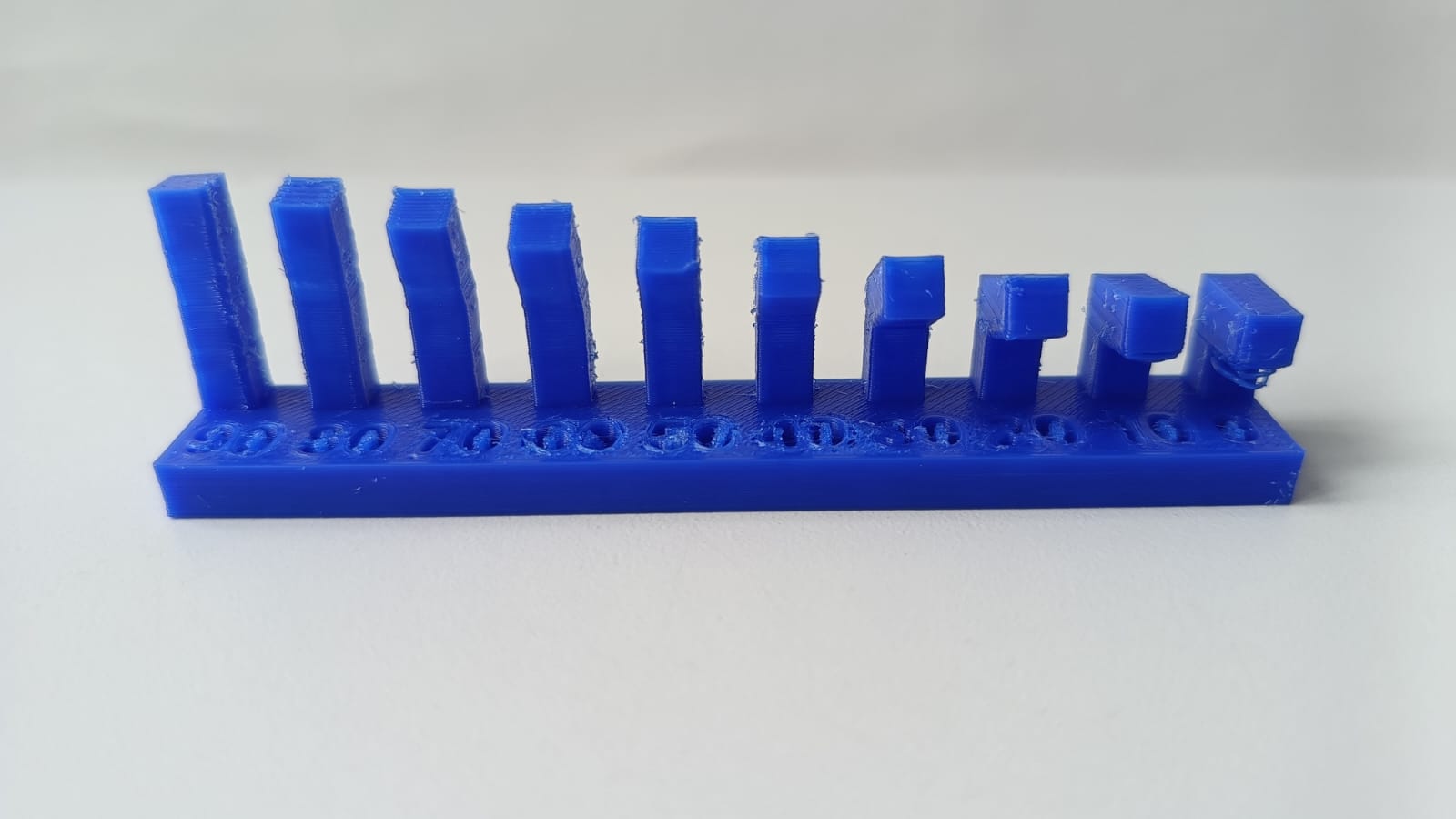
📐 Overhang Test
Overhangs up to 40° were printed cleanly, but beyond that point, there was a noticeable drop in print quality. Layer drooping was evident at steeper angles, suggesting that enabling supports or lowering the print speed would improve the results.
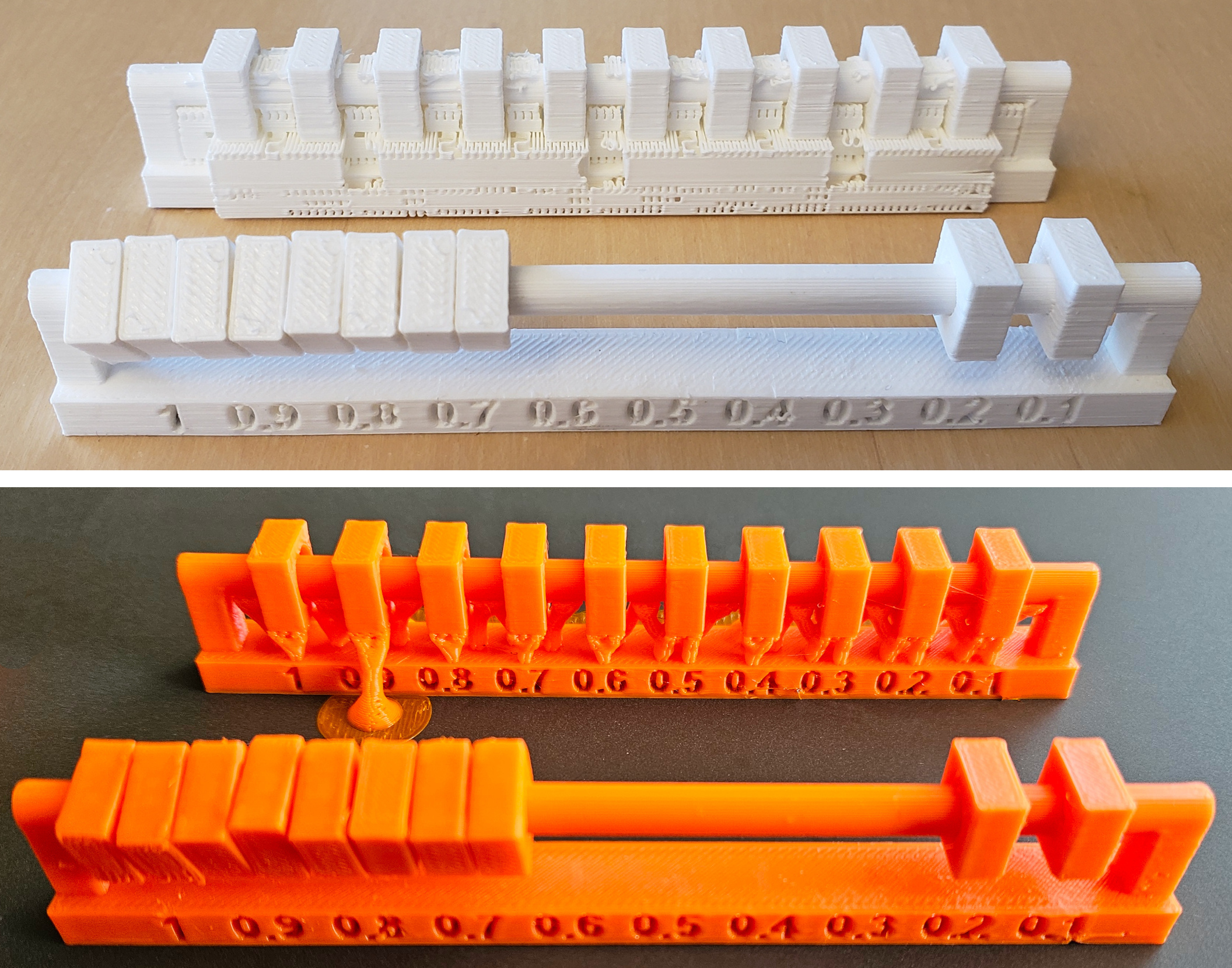
🌉 Bridging Test
Short bridges were handled well, but longer spans resulted in sagging and stringing between the ends. Increasing cooling and adjusting retraction and temperature settings should help reduce this issue in future prints.
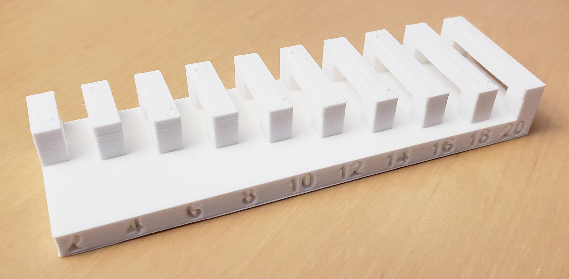
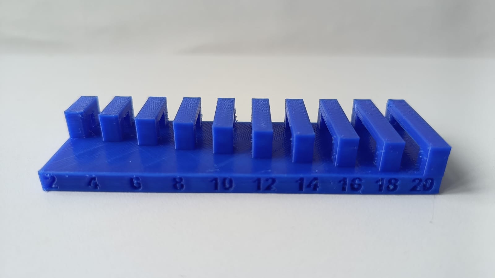
🏗️ Angle Test
The angle test revealed some visible stair-stepping on steep inclines. While this didn’t affect functionality, print quality could be improved by lowering the layer height or printing at a slower speed.
🧪 Surface Quality and Stringing
Stringing was observed between smaller features, which suggests the need to fine-tune retraction distance and speed. A cleaner surface finish can be achieved by optimizing these parameters.
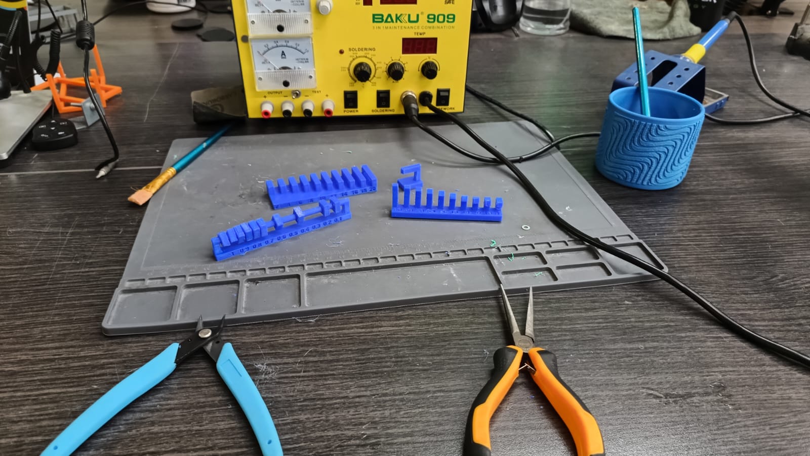
🛠️ Workspace and Tools
The testing was carried out in a prepared workspace with essential tools: flush cutters, tweezers, a scraper, and a heat-resistant mat. This setup made the printing and post-processing more efficient and safer.
✅ Conclusions
- Retraction settings need refinement to reduce unwanted stringing.
- Cooling plays a key role in successful overhangs and bridging.
- A clearance of at least 0.4 mm is required for moving parts to function properly.
- Supports should be used for angles greater than 45°.
- Regular calibration prints are essential to maintain and improve print quality.
Individual Assignment
3D Printing a Decorative Object
Using Fusion 360, a decorative object was designed to test organic curves and internal voids not feasible through subtractive methods. The design was exported to STL and sliced using Orca Slicer. The Ender 3 V3 SE printer was configured to use PLA at 200°C and a bed temperature of 60°C.
Fusion 360 T-Spline Practice
To achieve this assignment, I was guided by the video “Fusion T-splines are easy! | Day 27 of Learn Fusion 360 in 30 Days - 2024 EDITION” . I followed along with the practice exercise demonstrated in the video, but due to the size limitations and printer availability, I had to scale the final result down to a much smaller version.
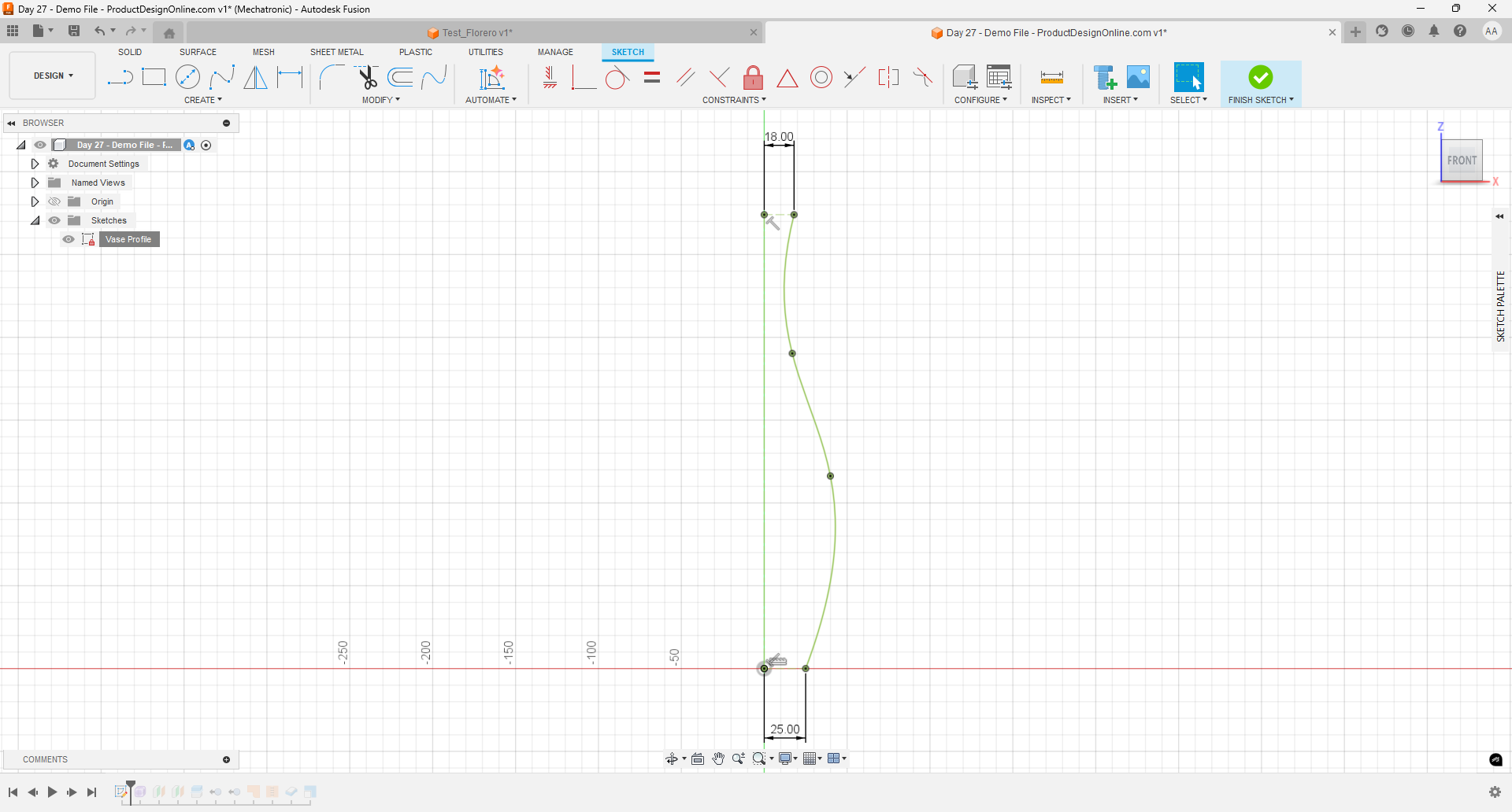
Using Reference Guides
As the first step, I followed the reference guides included in the base file. These lines helped define the top and bottom widths of the vase, serving as the structural limits for the entire shape.
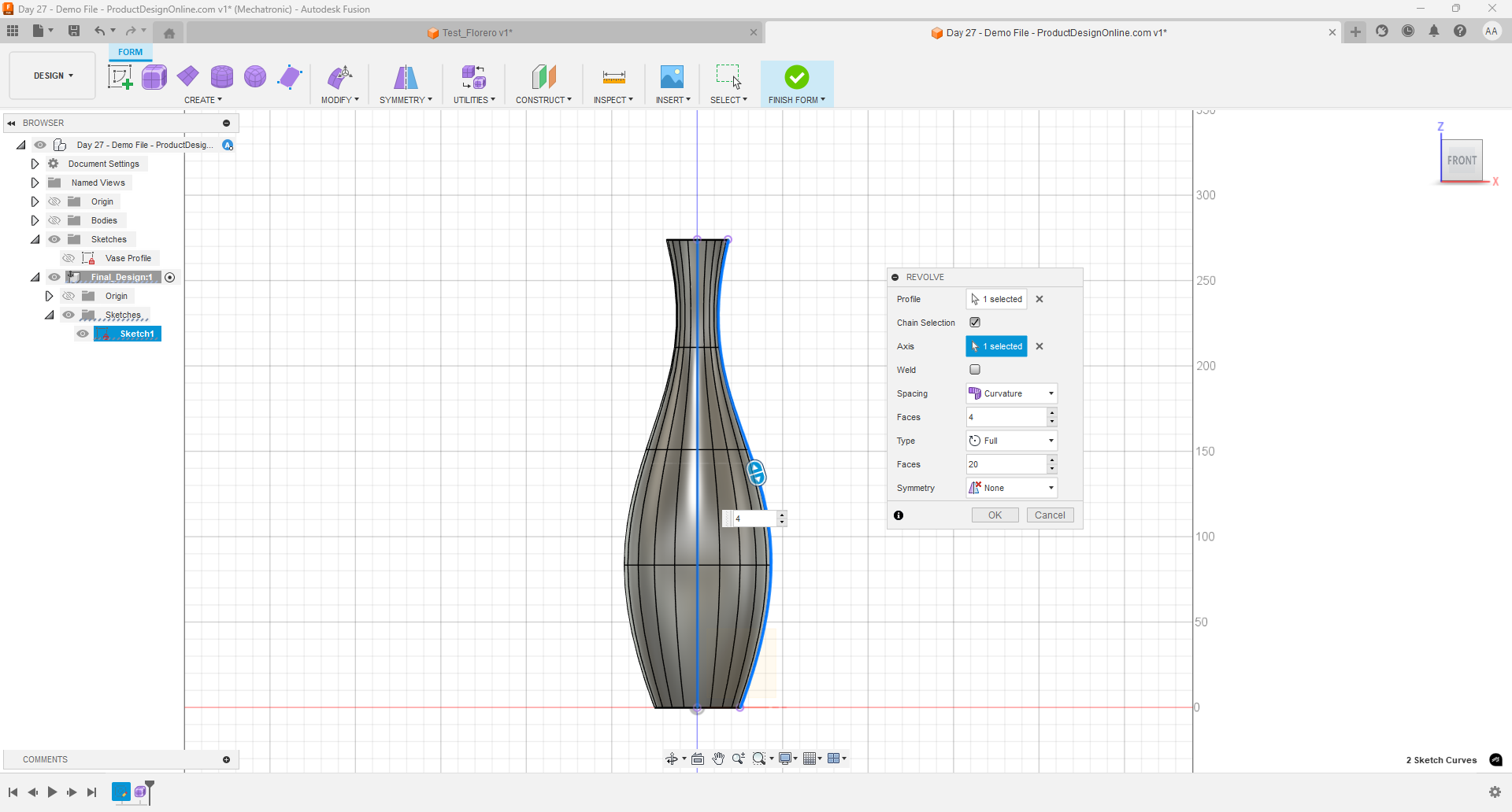
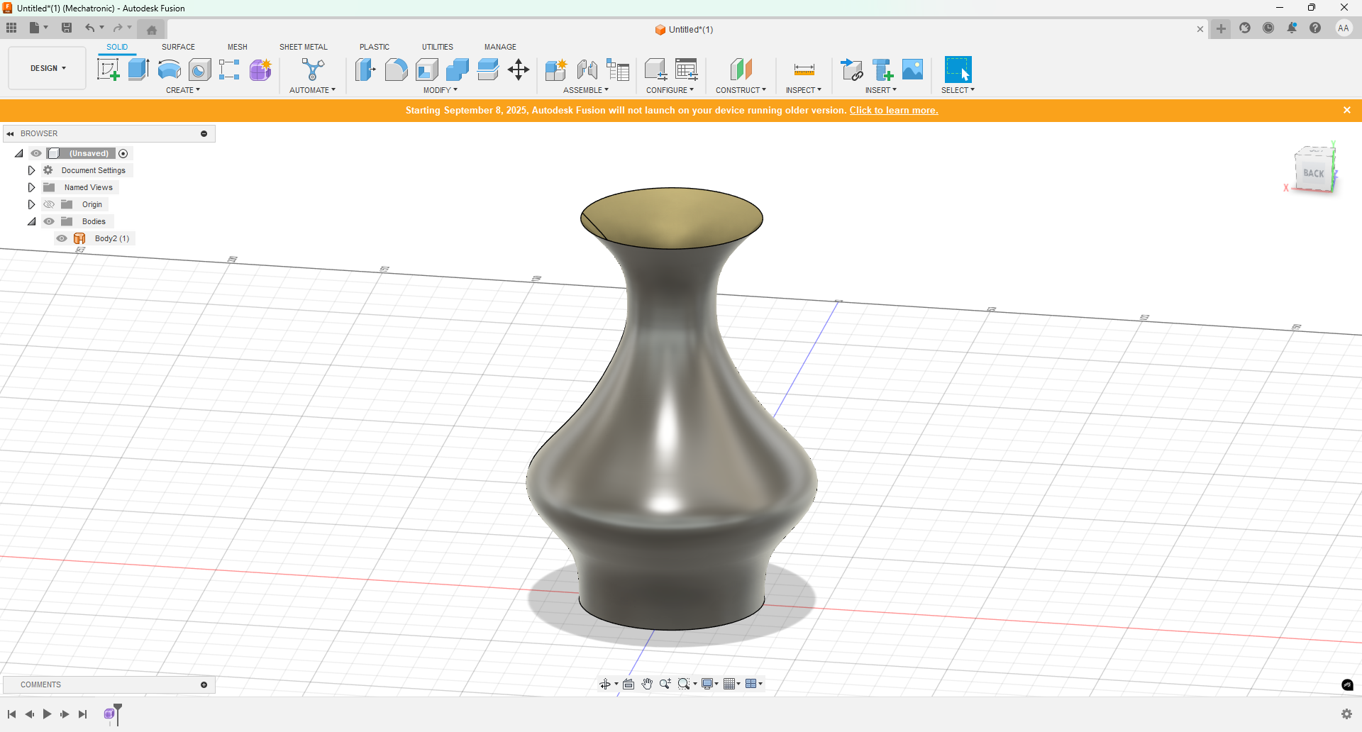
Revolve and Body Definition
Using tools like "Revolve", I created a new shape around the guide line. I defined parameters such as the number of horizontal divisions and faces, selecting 4 blocks and 20 faces to shape the structure of the vase.
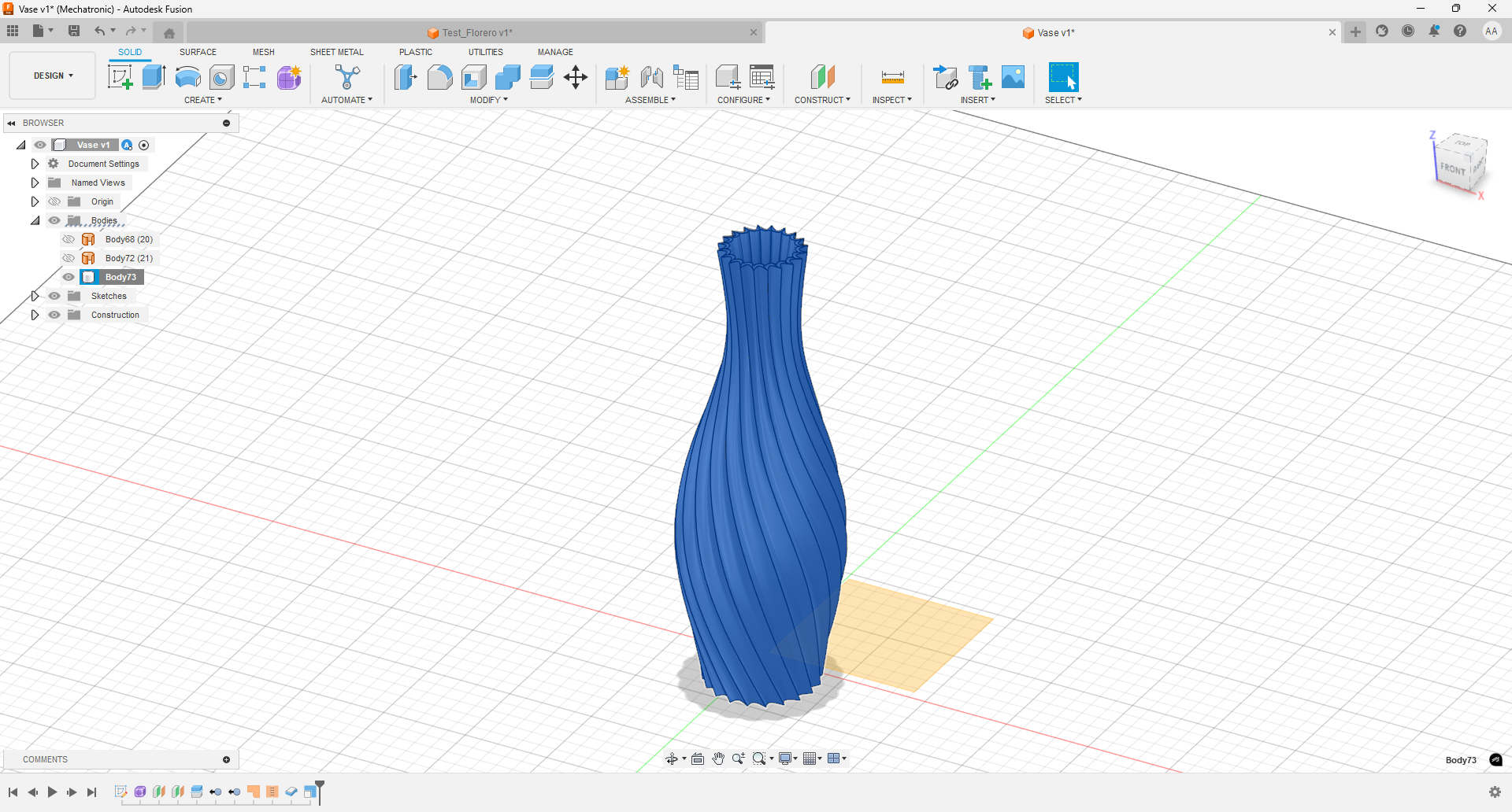
Section Rotation Setup
Following the tutorial steps, I created additional guide lines to divide the model into four different sections. Then, using the rotation tool, I rotated each section group by 45°, 35°, and 25° to achieve the desired twist style.
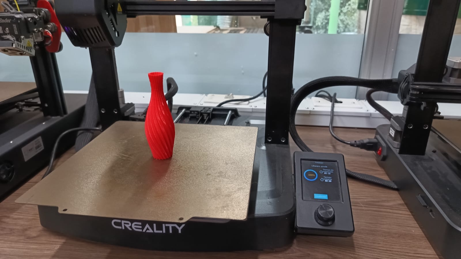
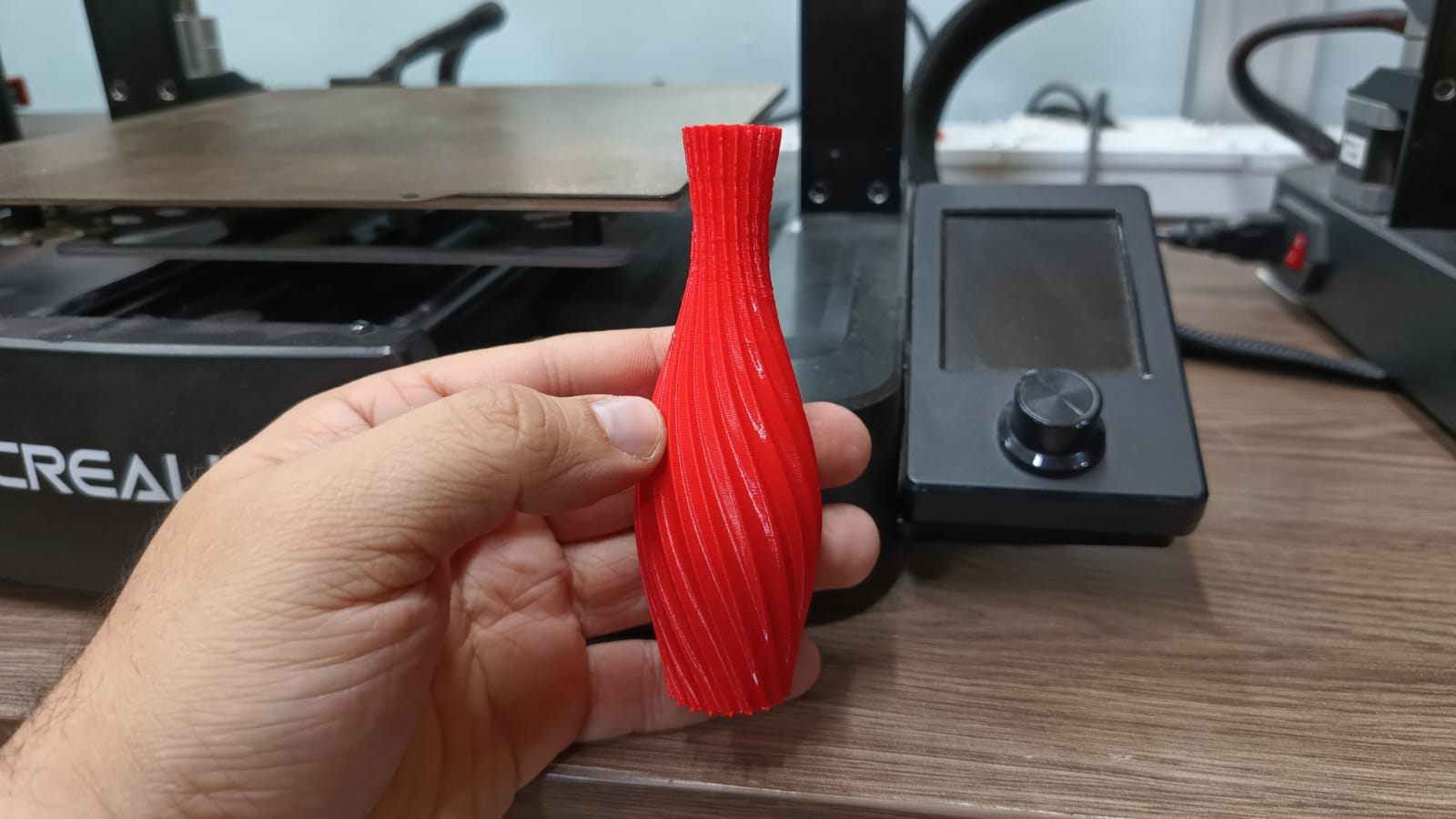
3D Printing Process and Final Results
After completing the 3D model design using Fusion 360, I proceeded to slice the object using Orca Slicer and printed it with PLA material on an Ender 3 V3 SE. The following images show the stages of the printing process and the final object. The result demonstrates good layer adhesion and clean geometry, validating that the design was suitable for FDM technology.
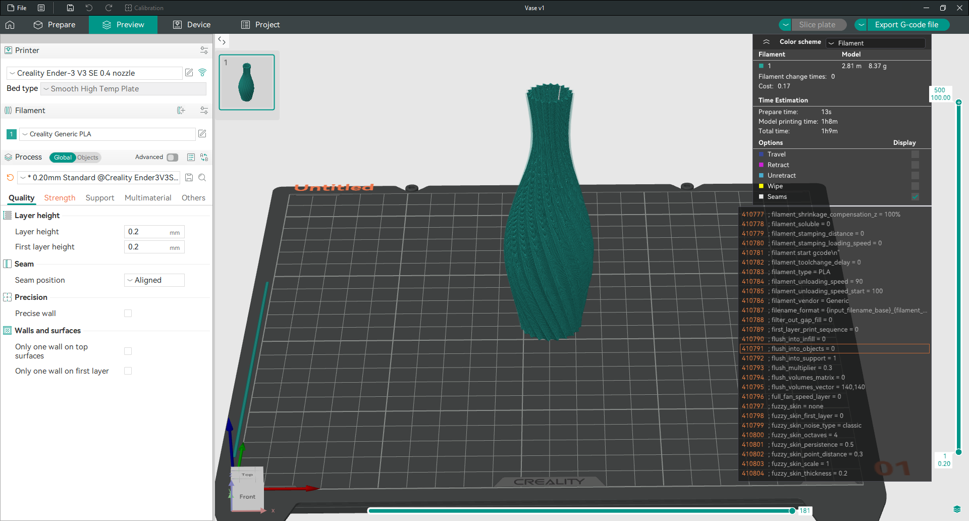
Screenshot of Orca Slicer showing the model preview and chosen settings.
| Parameter | Value |
|---|---|
| Printer | Creality Ender-3 V3 SE |
| Material | PLA |
| Slicer | Orca Slicer |
| Layer Height | 0.20 mm |
| Infill | 15 % |
| Extruder Temperature | 200 °C |
| Bed Temperature | 60 °C |
The print used approximately 8.37 g of PLA and took around 1 hour 9 minutes to complete. To export the G-code, simply insert a microSD card into PC and click the Export G-code file button in the top-right corner of the Orca Slicer interface.
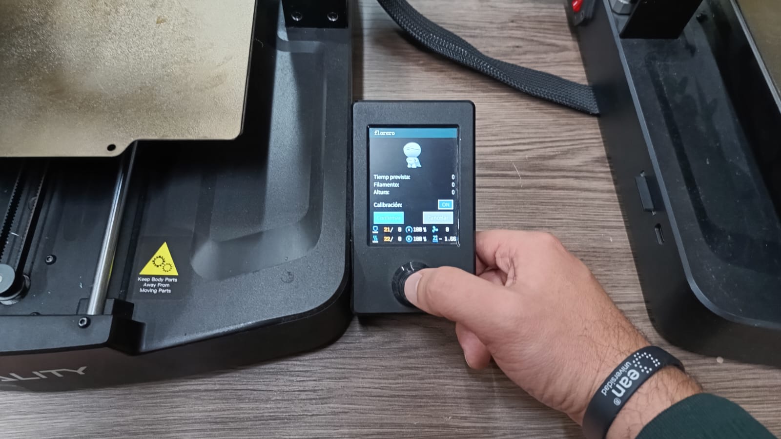
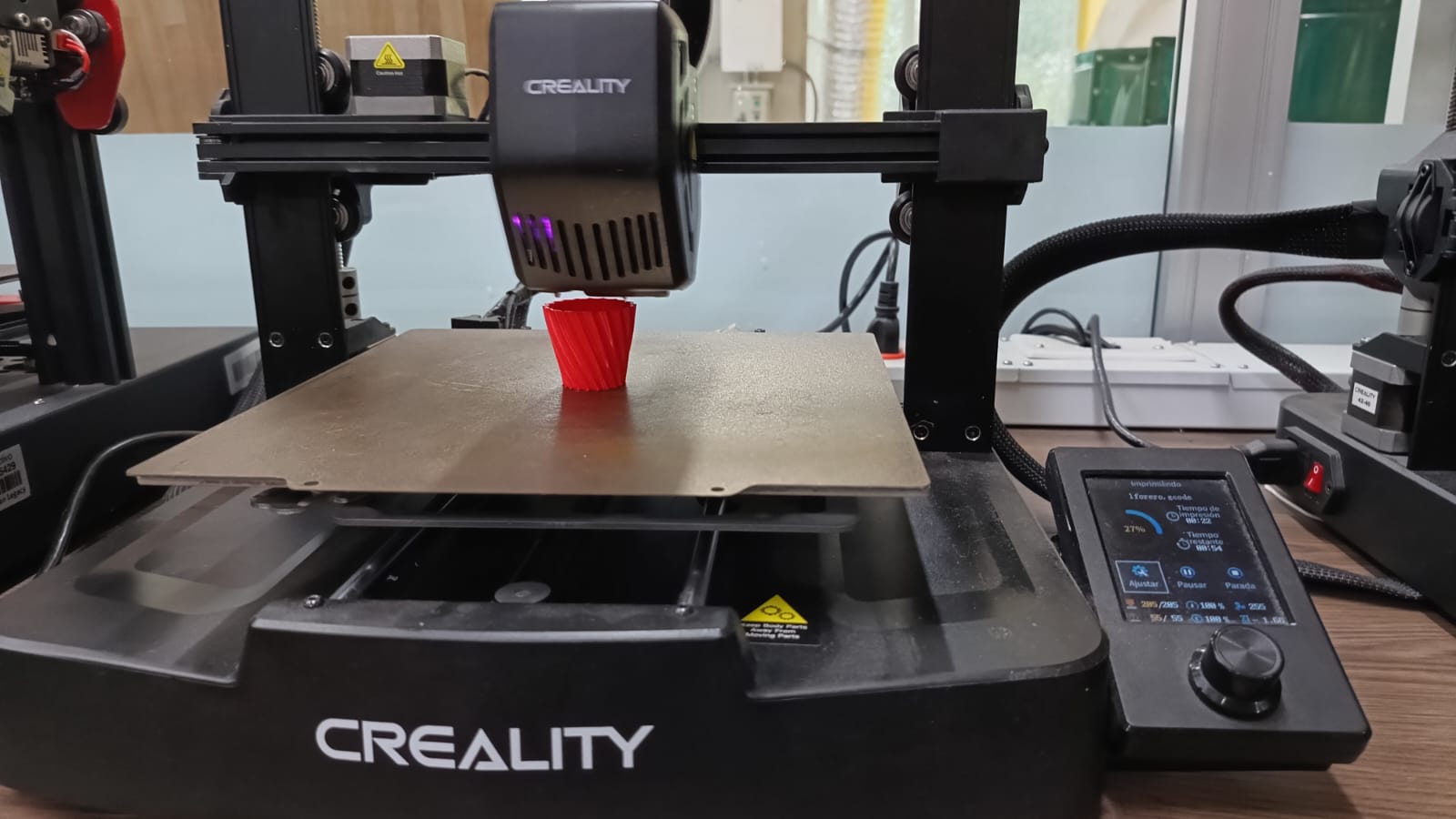
Starting the Print
This screen shows the selected file for the print job in the Ender printer interface: florero.gcode.
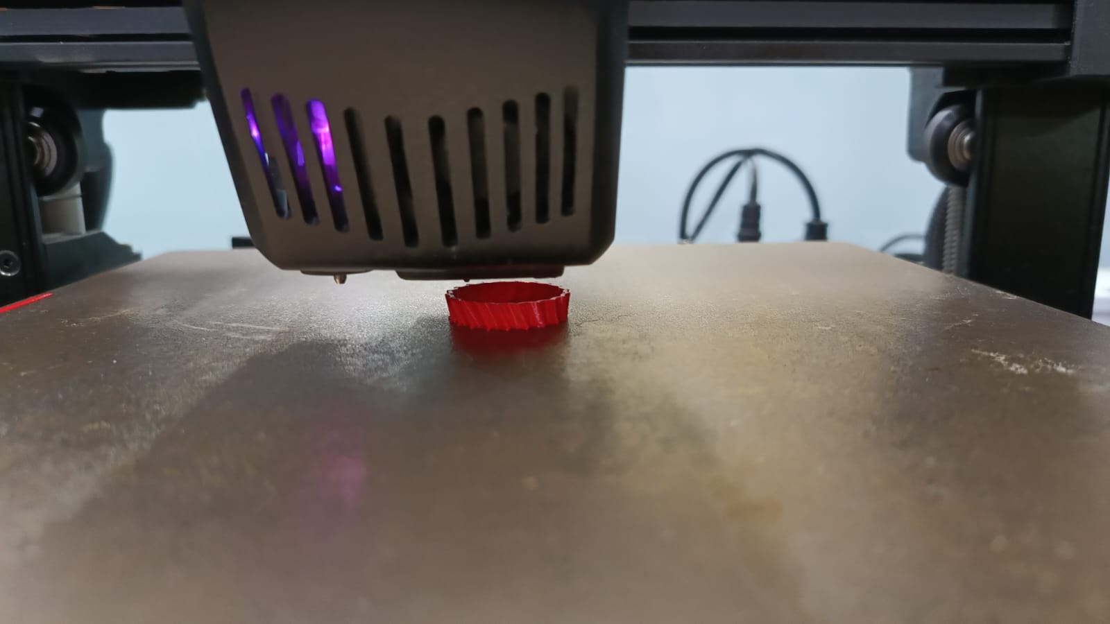
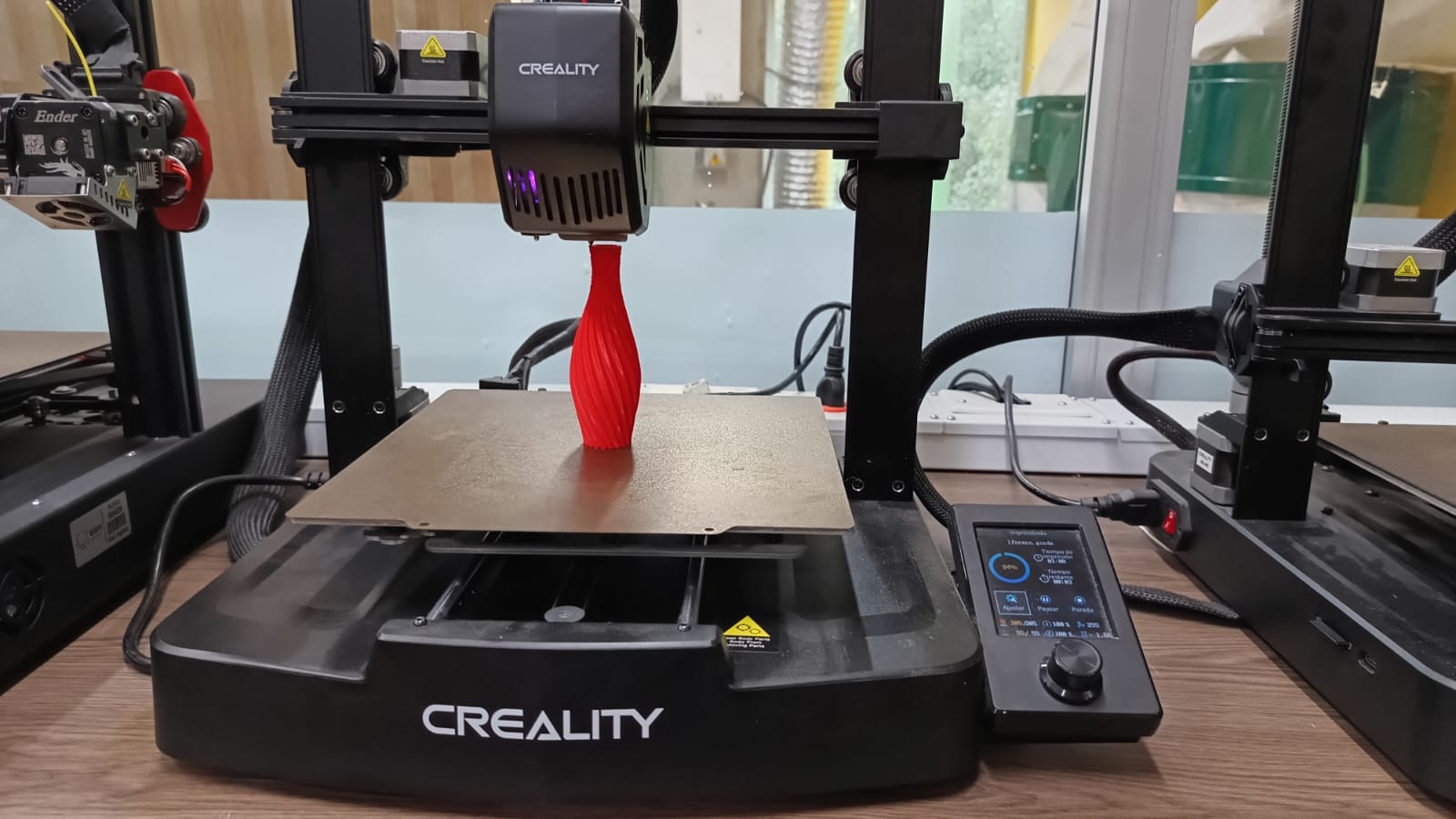
Mid-Print Progress
The vase begins to take shape as the printer progresses with the layered extrusion of PLA.
Conclusion
The object designed for 3D printing includes complex curves, rotational asymmetries, and internal geometries that would be extremely difficult to achieve using traditional subtractive methods. The layered construction enabled by additive manufacturing allowed for the realization of a fluid and elegant shape, which integrates continuous surface transitions and intricate structural details.
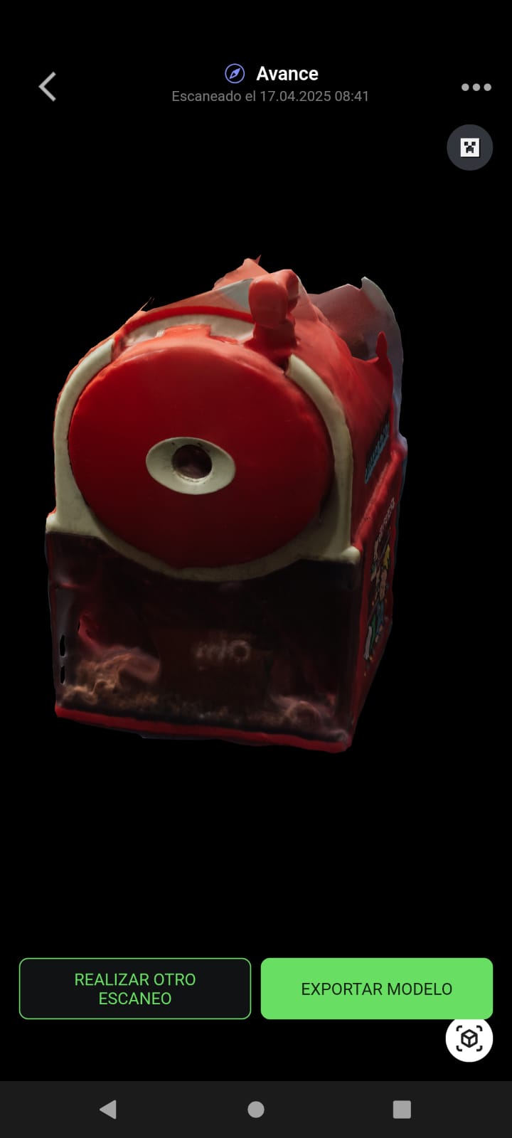
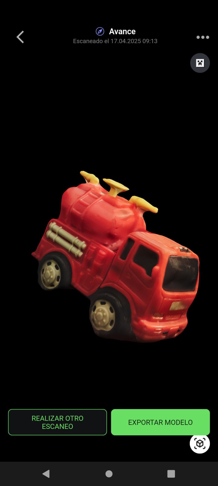
Previous Next3D Scanning with a Mobile App
Due to the availability of the FabLab 3D scanner, I had to look for an online application that would allow scanning using my phone. I used the MagiscanAI application to scan a pencil sharpener and then a toy fire truck. However, as shown in the images below, the results were not optimal. This was mainly due to poor lighting conditions and the difficulty of freely rotating around the object.
Reflections
This week offered a complete immersion into additive manufacturing processes, allowing me to design, print, evaluate, and refine objects using FDM technology. By testing STL calibration models—such as bridging, clearance, overhang, and angle—I could directly assess the printer’s capabilities and identify the optimal settings for precise, clean results.
The process of designing a vase with the Fusion 360 tools was especially interesting, as it forced me to think beyond standard geometric constraints and explore a form that could not be achieved with subtractive methods. After following the details of the tutorial and managing to modify it according to what I needed and the particular constraints of my project, I managed to have a good final prototype result.
Finally, experimenting with 3D scanning using mobile apps provided insight into the limitations of photogrammetry in uncontrolled environments. Despite the imperfections, the process helped me appreciate the importance of controlled lighting and object isolation in scan quality.
Downloads and Files
Below are the files used throughout the 3D printing and scanning process, including STL calibration models, Fusion 360 design exports, and other supporting resources: