Week 4
Embedded Programming
Introduction
During this week, the goal is to explore embedded programming by writing code for microcontrollers, simulating it, and when possible, running it on actual development boards. Emphasis is placed on understanding datasheets, toolchains, programming workflows, and interactions with input/output devices. The process also includes comparing platforms, using different languages or IDEs, and documenting what was learned throughout the assignment.
Group Assignment - Week 4
The objective is to demonstrate and compare the toolchains and development workflows for available embedded architectures. This involves hands-on testing and documentation of programming environments used across different microcontrollers.
Comparative Table of Microcontrollers
This table summarizes the technical specifications of the microcontrollers I plan to use during Embedded Programming week.
| Feature | Arduino Uno | ESP32-C3 | ESP32-S3 | RP2040-Zero |
|---|---|---|---|---|
| Architecture | AVR (8-bit) | RISC-V (32-bit) | Xtensa Dual-Core (32-bit) | ARM Cortex-M0+ (32-bit) |
| Clock Speed | 16 MHz | 160 MHz | 240 MHz | 133 MHz |
| Flash Memory | 32 KB | 400 KB + external | 512 KB + external | 2 MB |
| SRAM | 2 KB | 400 KB | 512 KB | 264 KB |
| GPIO Pins | 14 | 22 | 44 | 26 |
| Connectivity | None | Wi-Fi, BLE | Wi-Fi, BLE | None |
| USB Support | USB 2.0 | USB 2.0 | USB OTG | USB 1.1 Device |
Datasheets
Each document below is embedded for quick reference:
Arduino Uno
ESP32-C3
ESP32-S3
RP2040-Zero
Embedded Programming - Individual Assignment
For this week's assignment, my goal was to explore different microcontroller architectures by writing simple programs to interact with input and output devices. I selected four boards: Arduino Uno, ESP32-C3, ESP32-S3, and RP2040-Zero.
The core objective was to implement a basic program that reads a pushbutton and controls a LED based on the button state. Later, I plan to experiment with additional components such as sensors or actuators depending on the capabilities of each board.
Each board was also simulated before deployment, and the code was uploaded to verify interaction and real-time behavior. The results are presented below, along with source code and analysis.
- Microcontrollers: Arduino Uno, ESP32-C3, ESP32-S3, RP2040 Zero
- Simulation: Wokwi and Tinkercad
- Programming: Arduino IDE and Thonny.
- Task: Button and photocell as inputs, LED as output
- Planned Extensions: Use of temperature, light, or motion sensors
Each board's datasheet is embedded and a comparative table of technical specs is shown next.
General Wiring Diagram
To simplify prototyping and simulations across all selected microcontrollers, I designed a basic wiring diagram that includes the following components:
- Push Button: connected to a digital input pin and pulled down to GND.
- LED: connected to a digital output pin with a 220Ω resistor to GND.
- Photocell (LDR): connected in series with a resistor to form a voltage divider, and connected to an analog input.
This circuit enables simple digital input (button), analog input (photocell), and digital output (LED, buzzer) operations that can be implemented and simulated across all boards. The pin numbers will vary slightly depending on the platform used.
Wiring Diagram: Arduino Uno
In this experiment, I used an Arduino Uno to control two LEDs based on input from a push button and a photoresistor (LDR). The behavior is as follows:
- When the push button is pressed, the red LED connected to pin D9 turns on.
- When the LDR detects darkness, the green LED connected to pin D10 turns on and the red LED turns off.
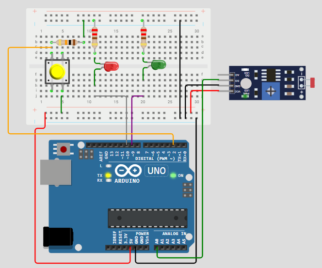
Connection Table
| Component | Connection Details |
|---|---|
| Photoresistor (LDR) |
One end connected to 5V The other end connected to a 1kΩ resistor to GND The node between LDR and resistor connected to analog pin A0 |
| Push Button |
One terminal connected to 5V The other terminal connected to digital pin D2 A 1kΩ pull-down resistor from D2 to GND |
| Red LED |
Anode connected to digital pin D9 via 220Ω resistor Cathode to GND |
| Green LED |
Anode connected to digital pin D10 via 220Ω resistor Cathode to GND |
Simulation with Wokwi – Arduino Uno
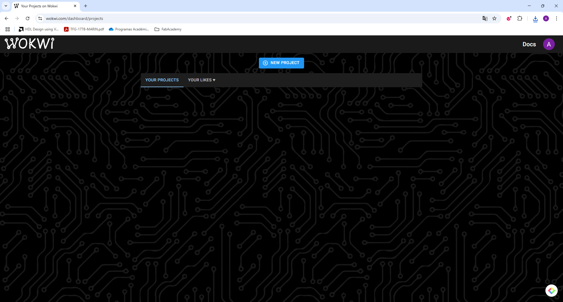
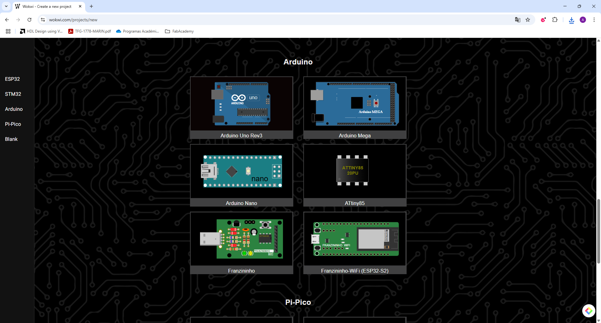
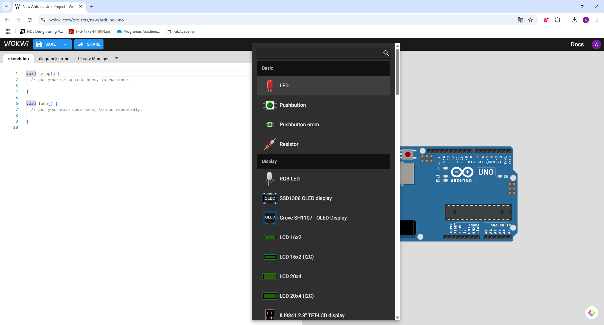
Before assembling the physical components, I tested the code and behavior of the circuit using Wokwi, a free online Arduino simulator. This allowed me to visualize the expected functionality, troubleshoot the logic, and make adjustments without any risk of damaging the hardware. It is essential to log in Wokwi creating an account and then starting a new project. In the plus icon you can see the different components of the application and on the left side you can build the code to be used in the simulator.
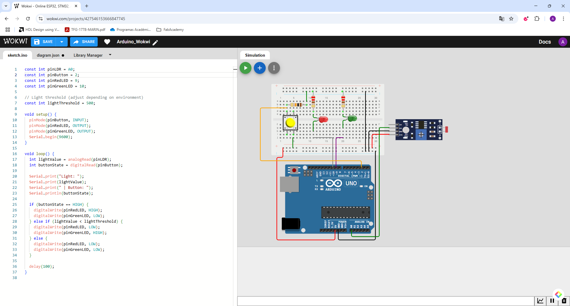
Schematic in Wokwi

Simulation Video
The video below shows how the circuit behaves: when the push button is pressed, the red LED lights up. If the environment is dark (detected by the photoresistor), the red LED turns off and the green LED lights up instead.
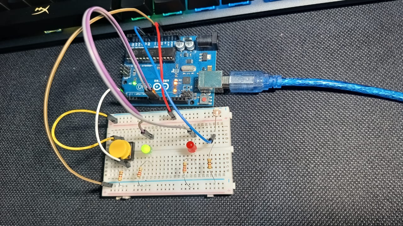
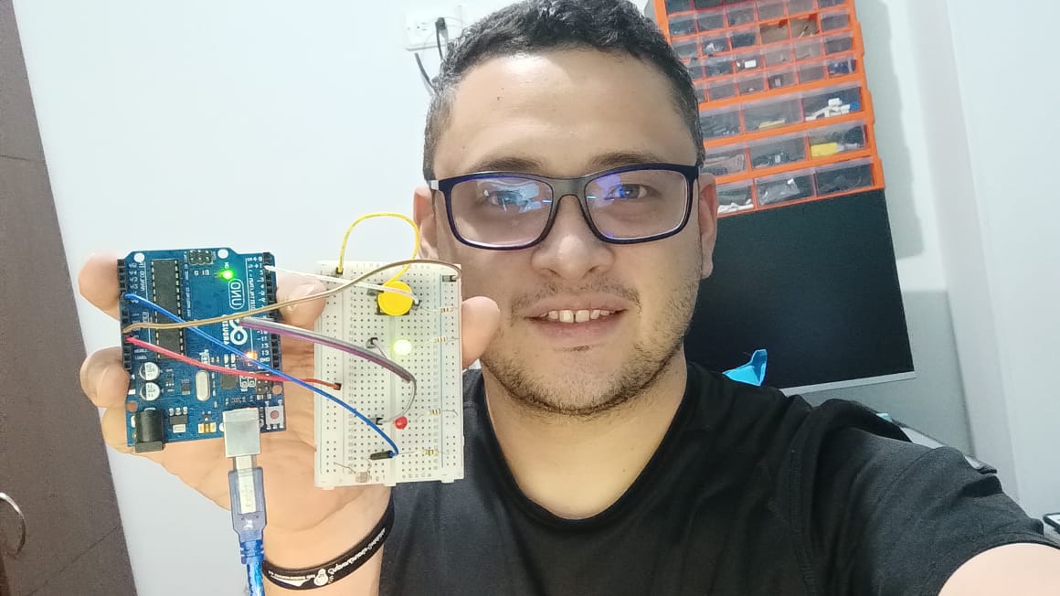
Real Assembly and Testing – Arduino Uno
After building and simulating the circuit, I assembled the components on a breadboard and programmed the Arduino Uno with the same code. Below are real photos and videos showing the setup and how it behaves.
Real Photos of the Circuit
Video: Code Upload and Serial Monitor
Video: Real Working Test
Reflections and Learnings – Arduino Uno
Working with the Arduino Uno allowed me to revisit the fundamentals of embedded systems programming. By using basic components such as a push button, two LEDs, and a photoresistor, I was able to create a small but functional decision-making circuit. This week emphasized the importance of simulating, prototyping, and testing to better understand both hardware behavior and software logic.
During the simulation phase with Wokwi, the logic of the system worked exactly as intended. However, once the physical circuit was assembled and tested, I noticed a discrepancy in behavior. Although the code was correct, the red LED did not switch to green when the light was low at night or indoors.
After reviewing the code, I realized that the lightThreshold value was too high for the ambient lighting conditions of my room. Originally, the threshold was set to 500, which is more appropriate for environments with very bright light. In a real setting—especially at night with regular indoor lighting—the photoresistor wasn’t reaching values high enough to trigger the change.
Download the source code: light_button_led.ino
ESP32-C3 - Light Sensor and Button Control
This setup uses the ESP32-C3 microcontroller to demonstrate basic interaction through a button and a light sensor (LDR), with two LEDs as outputs. When the button is pressed, the red LED turns on. When low light is detected, the green LED turns on, and the red LED turns off. The values were tested and simulated using Wokwi.
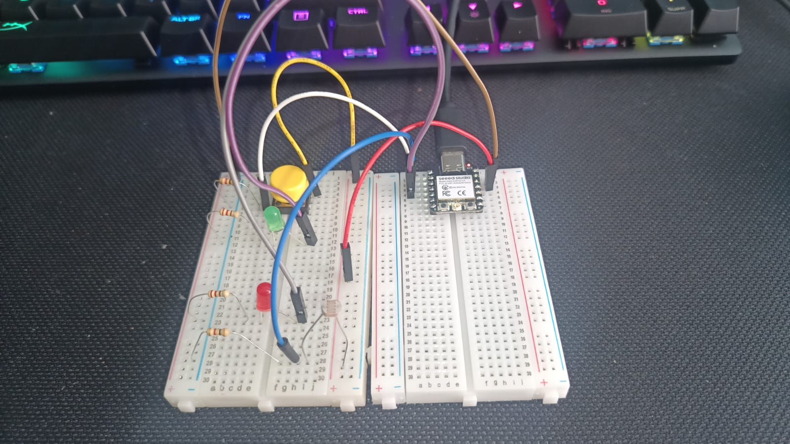
Component Connections
- LDR (light sensor): connected between 3.3V and a 1kΩ resistor to GND. The midpoint is connected to
GPIO3. - Pushbutton: connected between 3.3V and a 1kΩ pull-down resistor to GND. The midpoint goes to
GPIO2. - Red LED: connected to
GPIO4with a 220Ω resistor to GND. - Green LED: connected to
GPIO5with a 220Ω resistor to GND.
Wokwi Simulation
This project was simulated using Wokwi. You can access and test the interactive circuit using the link below:
Real Setup
Real pictures and video of the test using ESP32-C3.

Video: Real Working Test
Download Code (.ino)