Week 3
Computer-Controlled Cutting
Group Assignment: Lab Safety and Laser Cutter Characterization
Lab Safety Training
As part of the group assignment, I completed the safety training provided by the lab. This training included proper handling of materials, emergency procedures, use of protective gear, and safe operation of machines. I also reviewed safety signage and the location of fire extinguishers and emergency buttons within the lab workspace.
Laser Cutter Used
The laser cutter available in the lab is the Bodor 150W CO₂ Laser Cutter. It is suitable for cutting and engraving various materials such as acrylic, MDF, plywood, and leather, and is equipped with autofocus and fume extraction.

Technical Specifications
- Power:limited power to 80% of its normal power due to machine wear protection
- Type: CO₂ Laser Cutter
- Work Area: Approximately 1300 mm x 900 mm
- Resolution: Up to 1200 DPI
General Specifications
- Safety and Visibility: Fully enclosed system with transparent lid, laser pointer for previewing the cutting area.
- Precision and Quality: Air assist system to reduce burning and improve cut accuracy, plus a calibration grid to test speed and power.
- Integrated Features: Digital control panel and built-in ventilation system for efficient air extraction.
- Design Flexibility: LightBurn supports SVG, DXF, AI, and BMP file formats, making it compatible with most design workflows.
- Control and Precision: Allows fine adjustment of speed, power, and laser frequency for each job.
- Process Optimization: Includes job preview simulation.
Characterization Tests
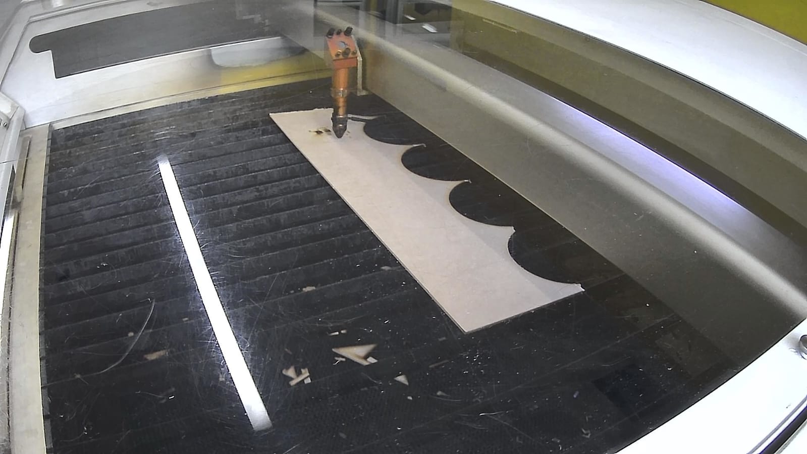
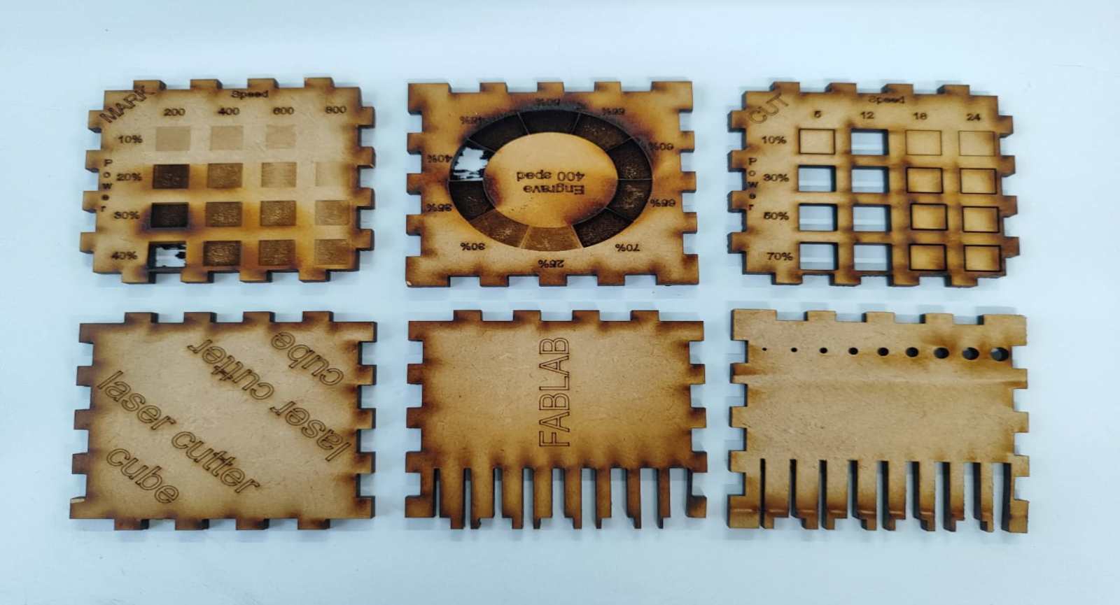
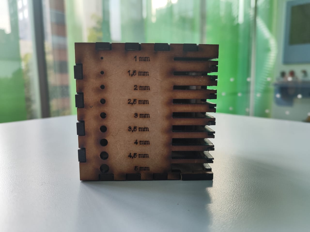
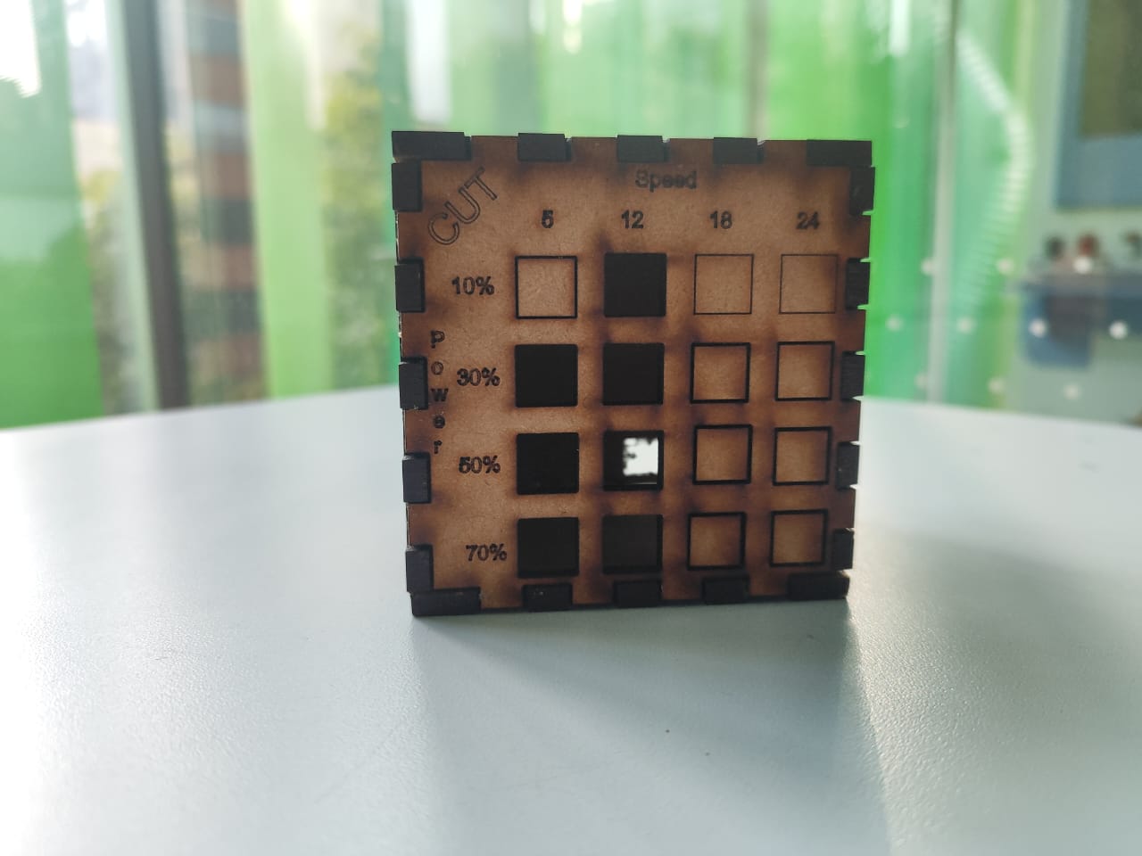
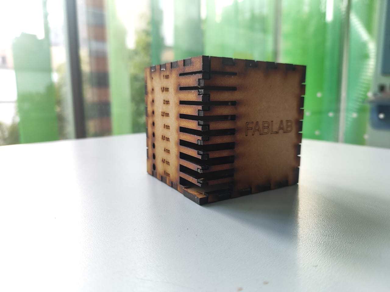
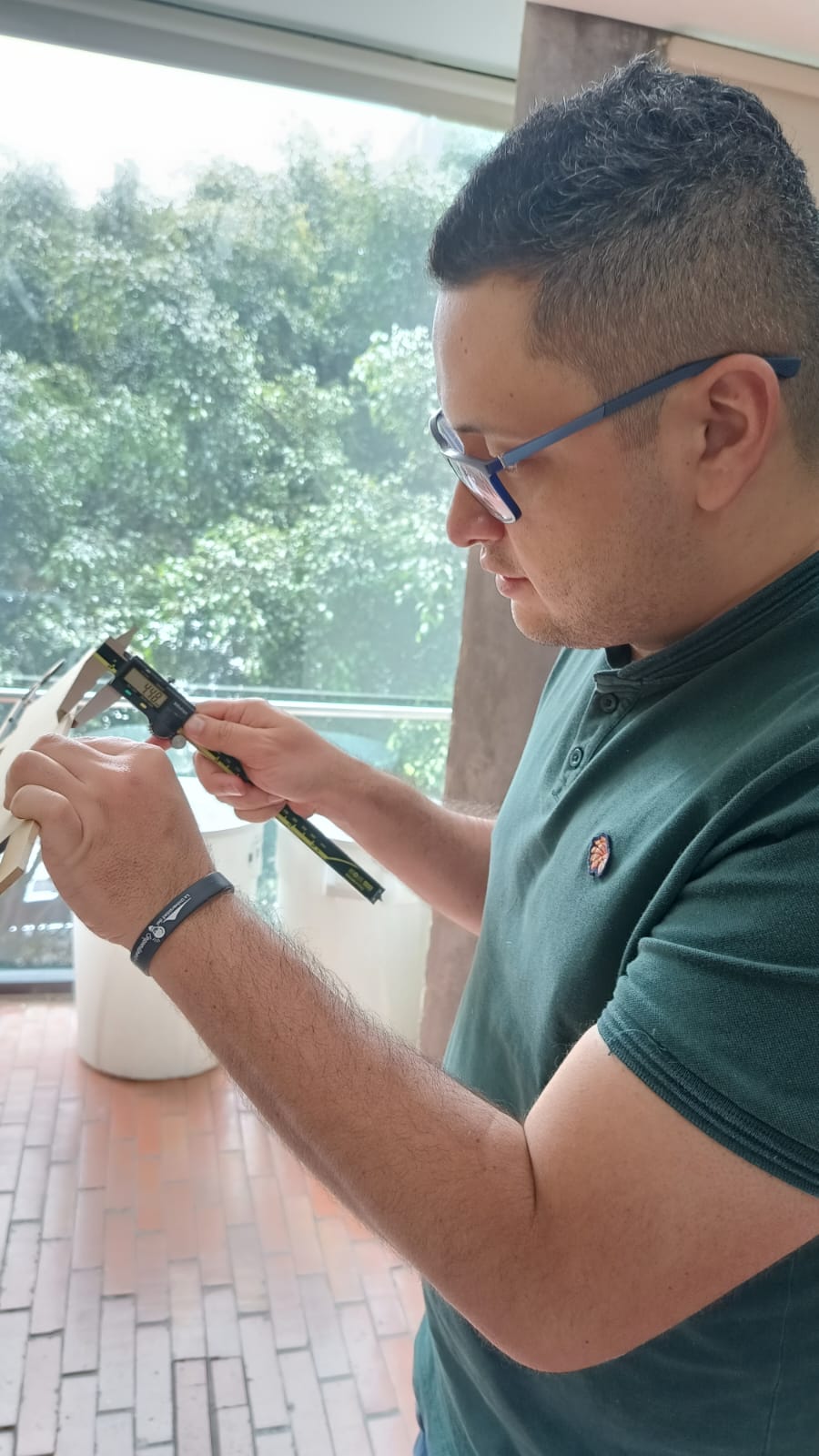
My contribution to the group work consisted of building a cube to be able to measure the different speeds, marking, engraving, power and additionally to be able to determine the widths I need to fit the various pieces.
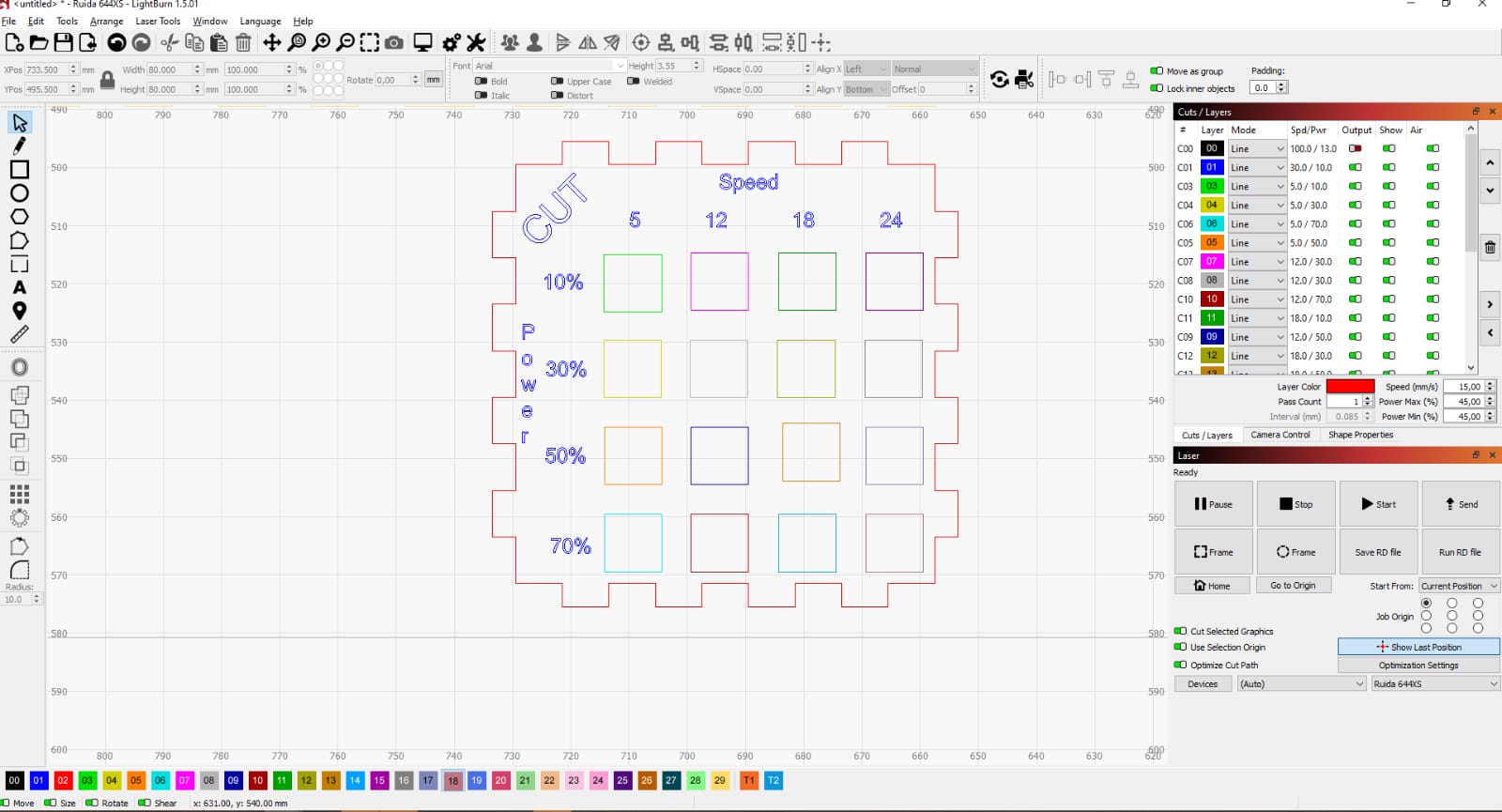
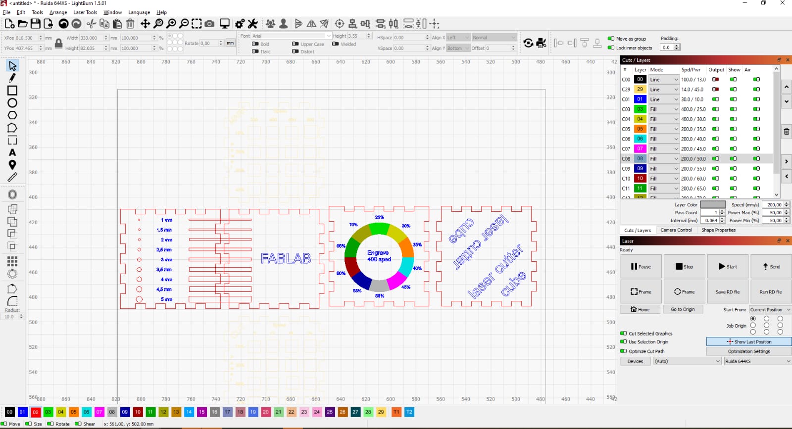
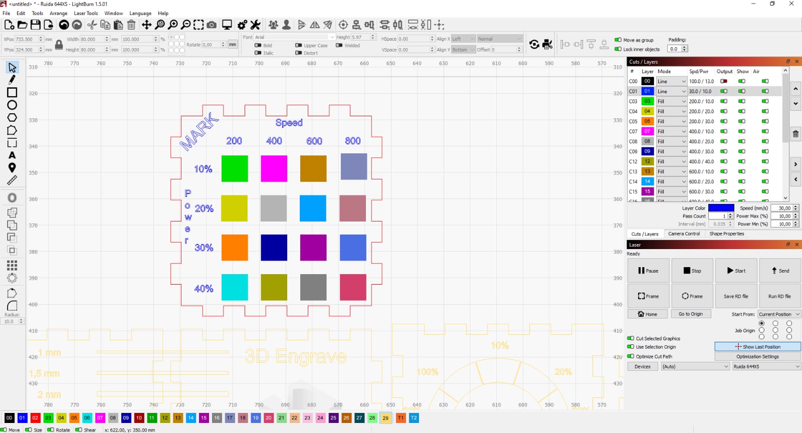
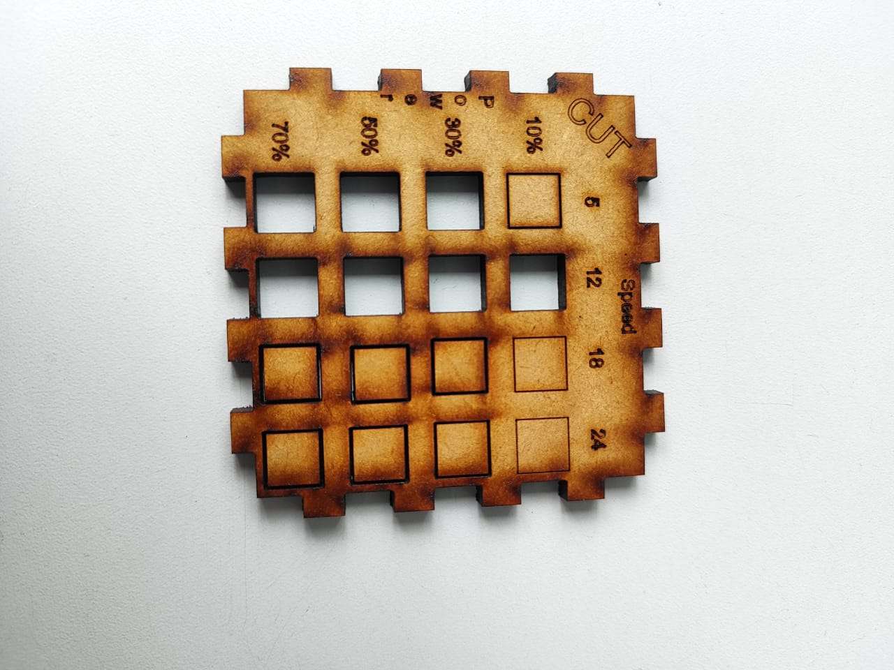
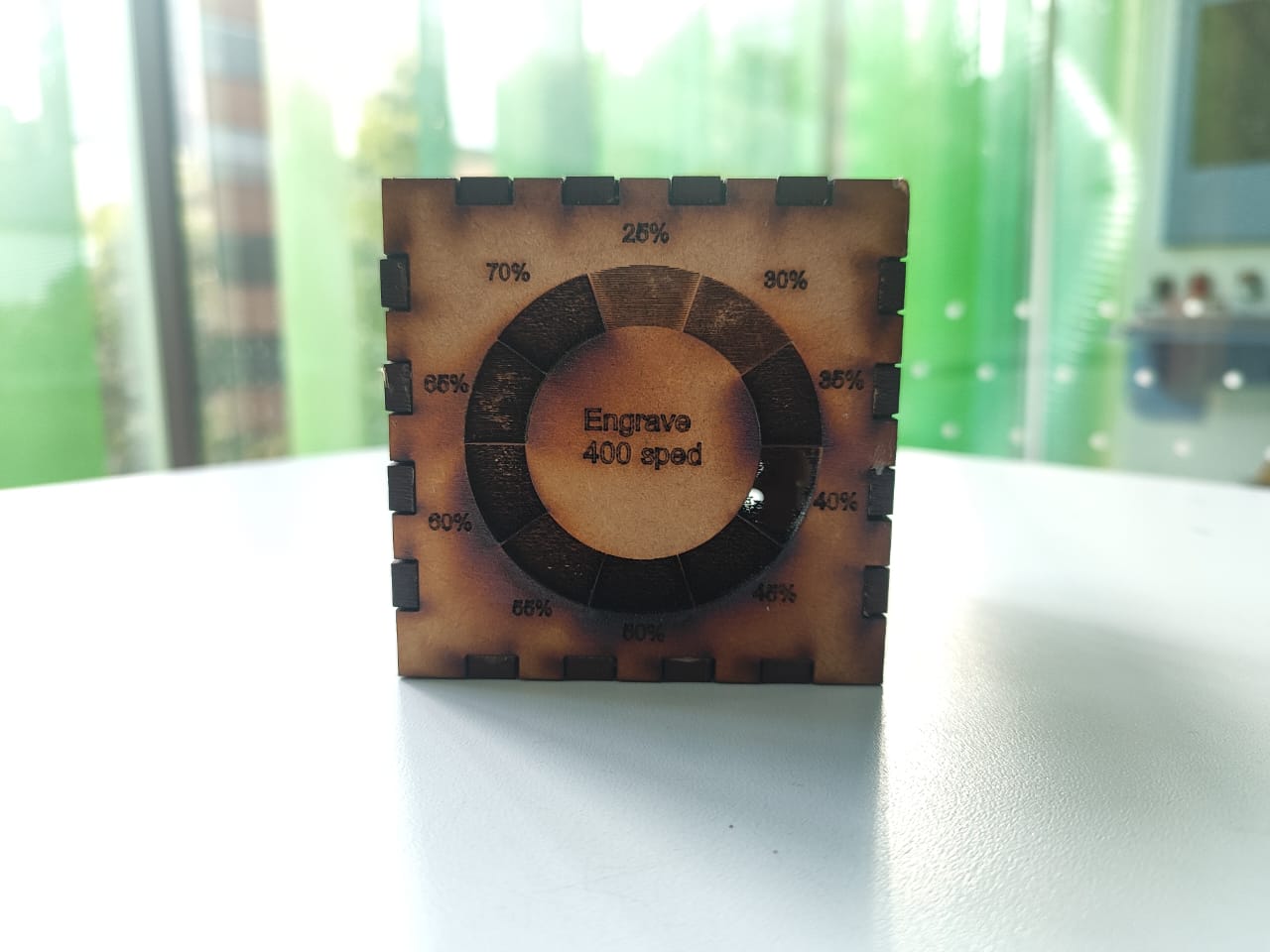
After the whole design process, I proceeded to make the cuts and engravings on the machine, obtaining the following results.
Personal Reflection and Conclusions
Participating in the group assignment this week allowed me to understand in greater depth how power and speed settings directly affect the quality and precision of laser cutting and engraving. Through systematic testing, I was able to observe how minor adjustments in parameters can result in significant differences in outcomes, both visually and structurally.
I particularly learned the importance of balancing power and speed to avoid excessive burning or incomplete cuts, and how visual contrast in engraving is often achieved at the cost of material depth. Additionally, experimenting with friction fit tolerances helped me appreciate the precision required for mechanical assemblies without adhesives.
This hands-on experience strengthened my ability to make informed decisions when selecting laser settings based on the functional and aesthetic needs of a project. It also reinforced the value of collaborative testing and documentation when exploring manufacturing techniques.
Individual Assignment
The objective of this assignment was to:
- Cut something on the vinyl cutter: Explore and operate the vinyl cutter to create custom stickers or patterns.
- Design a parametric construction kit: Create a flexible and modular design that can be laser cut and assembled in different ways.
- Document the process: Consider the laser cutter’s kerf and show how the design fits together in multiple configurations.
Parametric Design in Fusion 360
This section explains step by step how I built a basic parametric model using Fusion 360, focused on designing a construction kit that can be laser cut and assembled in different ways.
opening software
In the previous week I selected fusion 360 as the software I was going to use for my designs.
Drawing the first figure
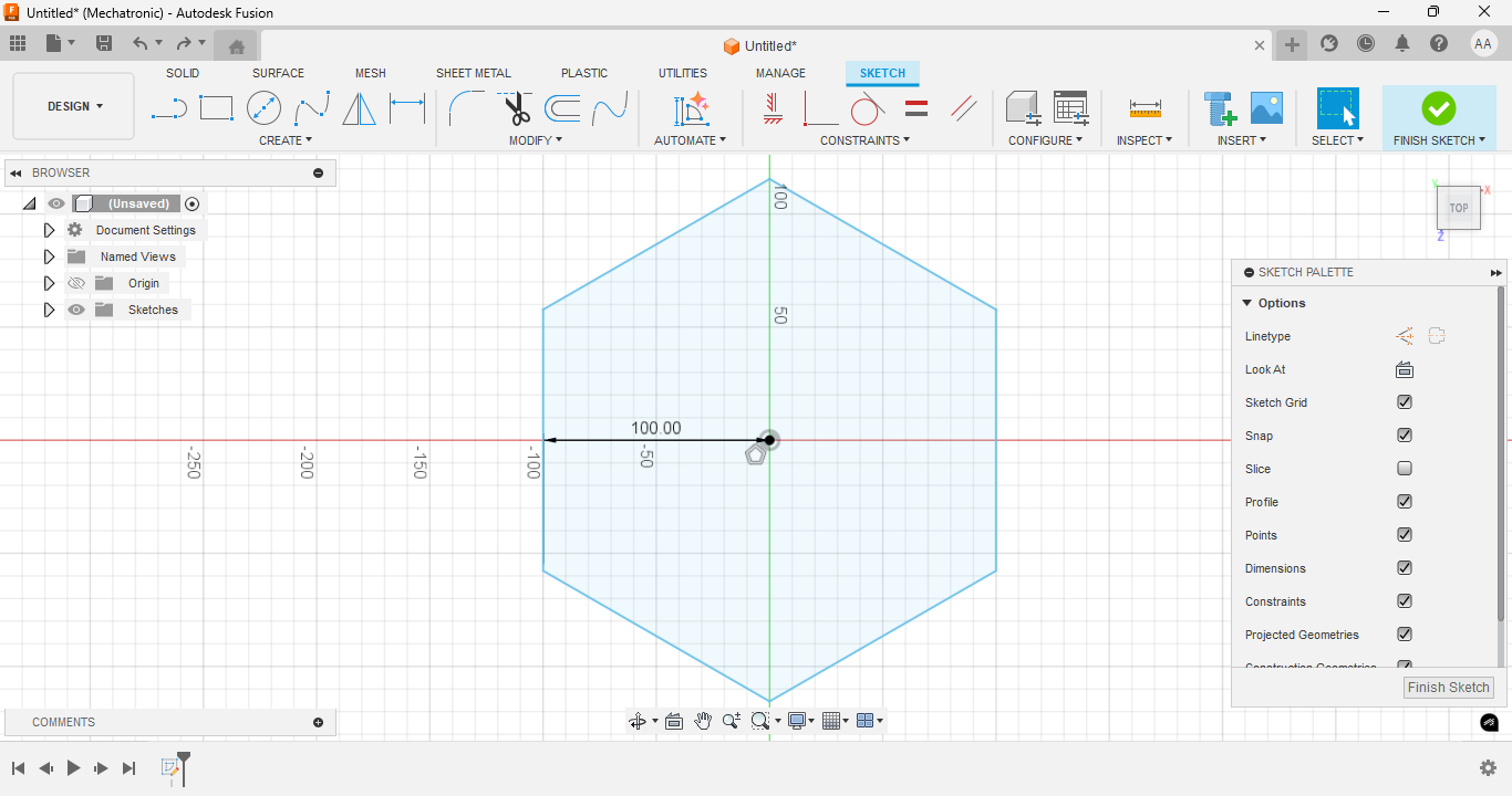
Now, I opened a new drawing and looked for a shape that would be easy to generate and edit to fulfill the assignment of the week, so I selected a hexagon. I defined a horizontal reference of 100 mm from the origin to start constraining the shape
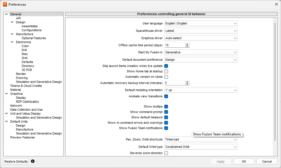
Changing the preferences
In the preferences menu I changed the language to English to make it easier for people following this tutorial, I even changed the way I wanted to control the drawing since I am more familiar with Tinkercad.
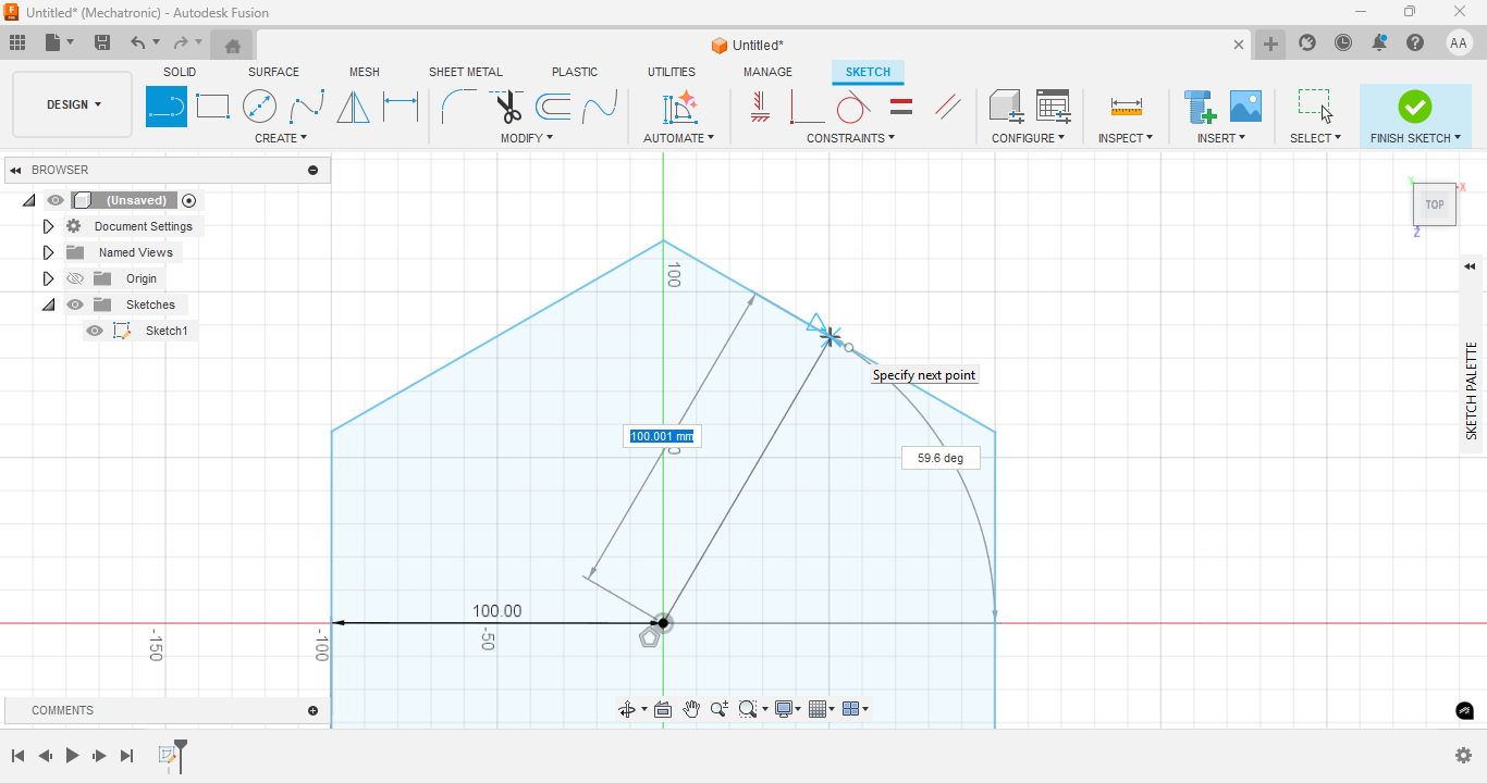
Creating construction geometry
I drew construction lines to help with symmetric placement of future shapes and constraints.
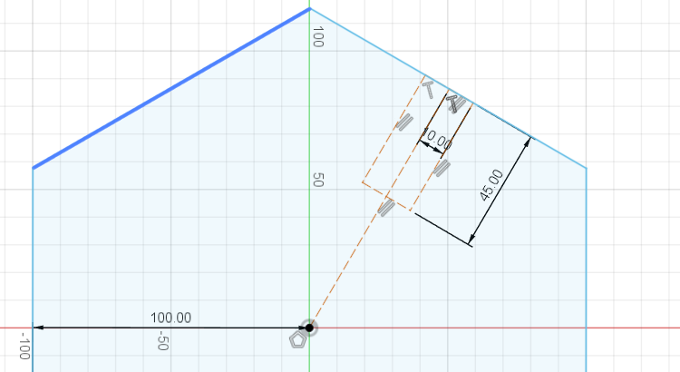
Dimensioning internal slot
I have added a 10 mm dimension to one edge of the internal groove to control its width, in the same way, pressing the letter “x” on the line I have just drawn makes it only a guide and not part of the drawing, this makes it easier to see the other lines.
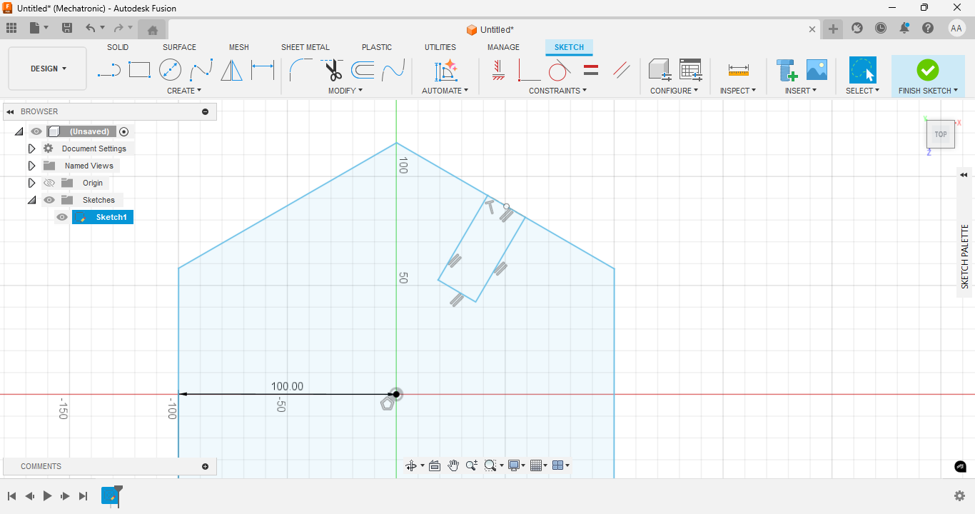
Drawing a rectangle
I drew a rectangle using the 3-point rectangle option with arbitrary measurements such as width and distance to the center. Spoiler: as I did not take into account the thickness of the material, later this design did not work.
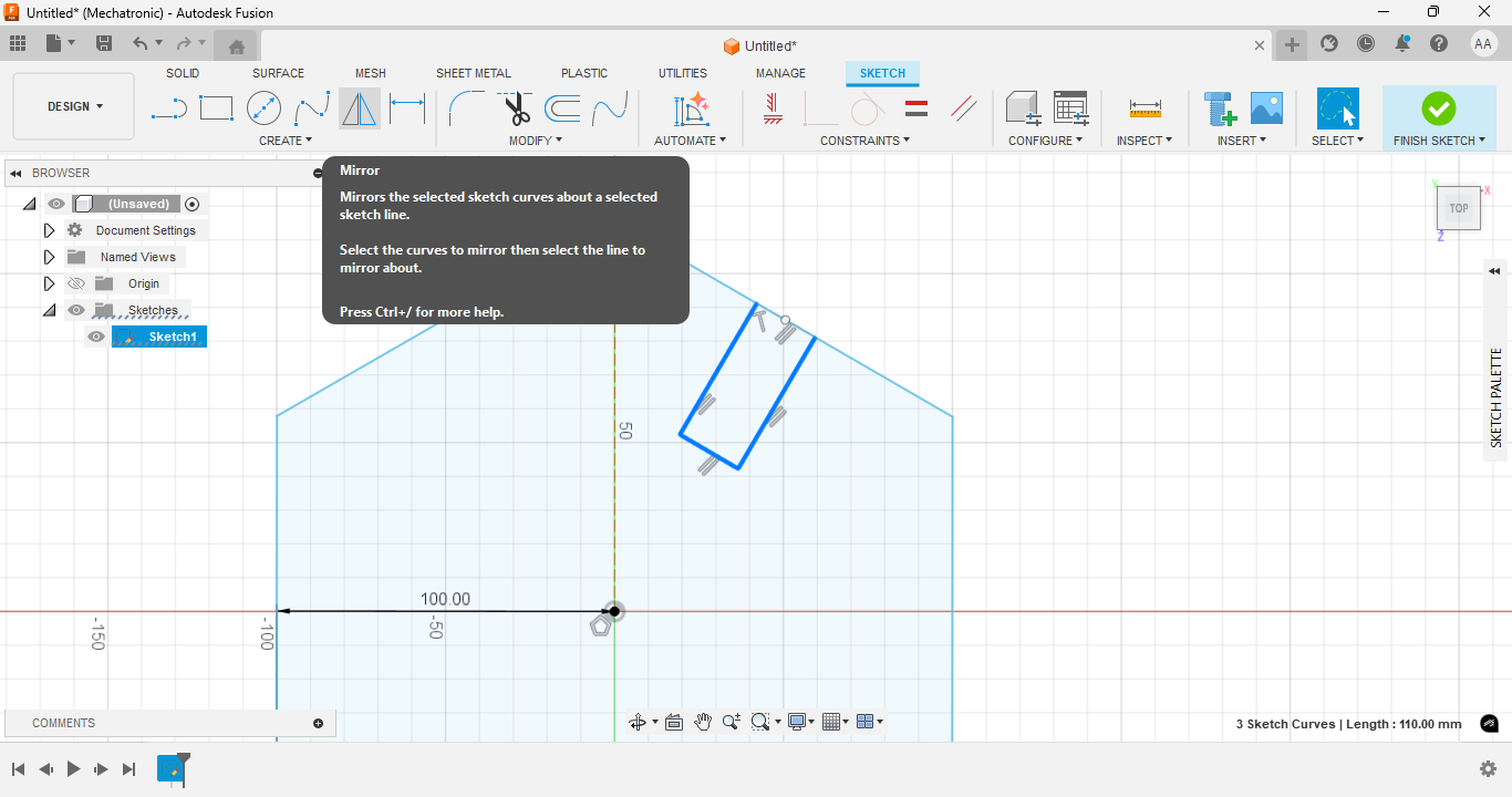
Mirroring the geometry
I mirrored a set of slots on the opposite side using the mirror tool and selecting the center line that I had previously drawn to indicate with respect to which point I should mirror. It is important to select only the lines that you want to mirror.
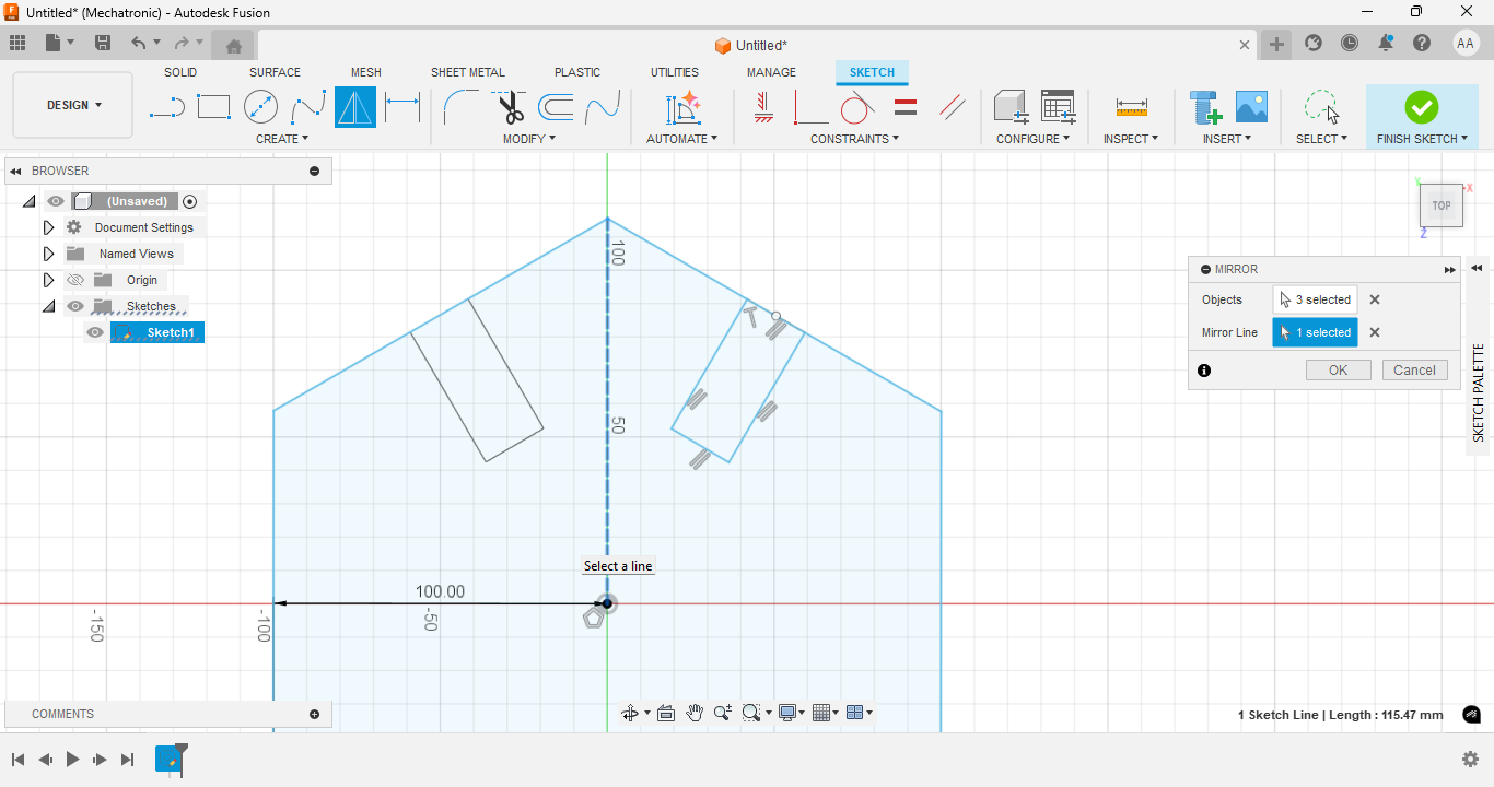
Mirroring the top slot
I repeated the mirror operation on the top portion of the design for symmetry.
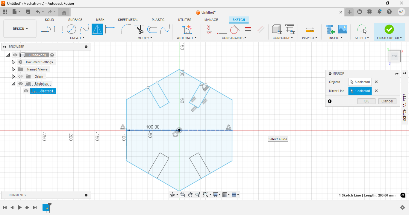
Selecting objects and centerline to mirror
Now I repeat the same operation but to mirror the upper part on the lower part and thus have 4 slots.
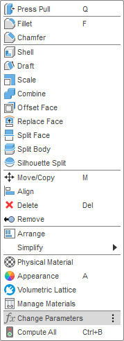
Accessing Change Parameters dialog
I opened the Change Parameters dialog to define user parameters and make the model parametric.
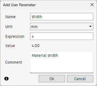
Creating a user parameter called Width
I defined a user parameter named Width with a value of 4 mm to match the material thickness.
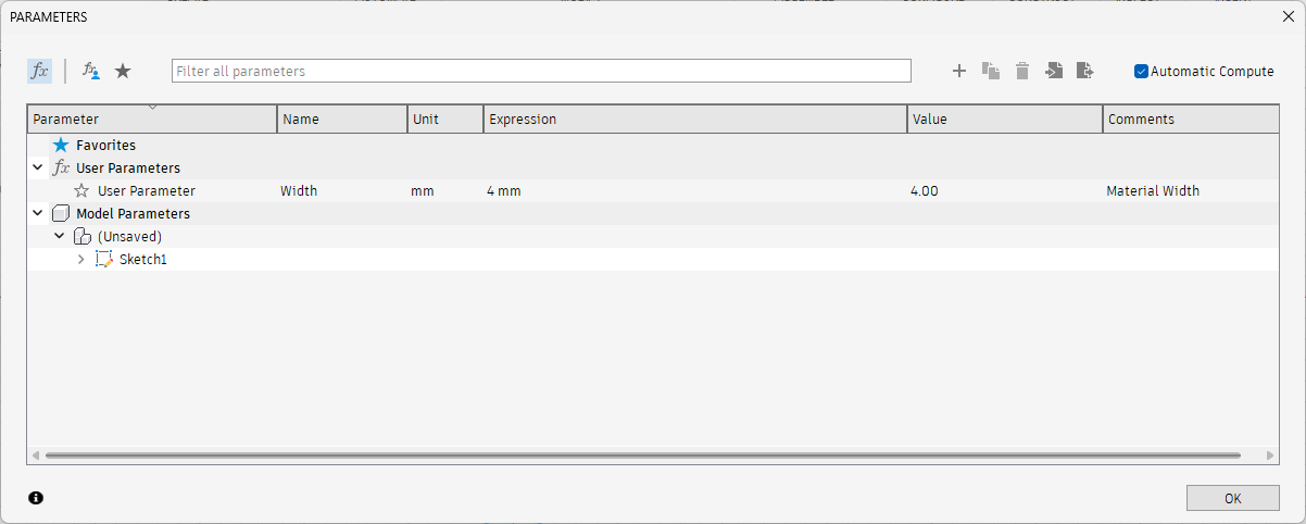
Confirming parameter creation
The new user parameter "Width" appears in the parameter list under User Parameters.
Cleaning geometry using Trim and using the Width parameter in the extrusion
Using the trim tool, I removed unwanted sections of lines to clean up the sketch. During extrusion, I typed “width” to apply the thickness parameter to the body.
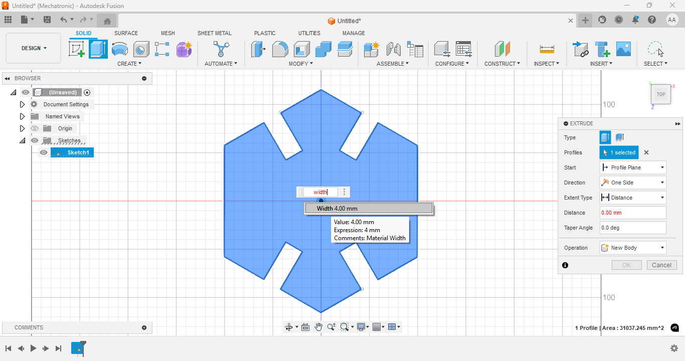
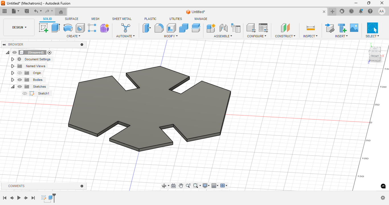
Extruding the model into 3D
The final body is extruded using the defined parameter, completing the 3D construction kit part.
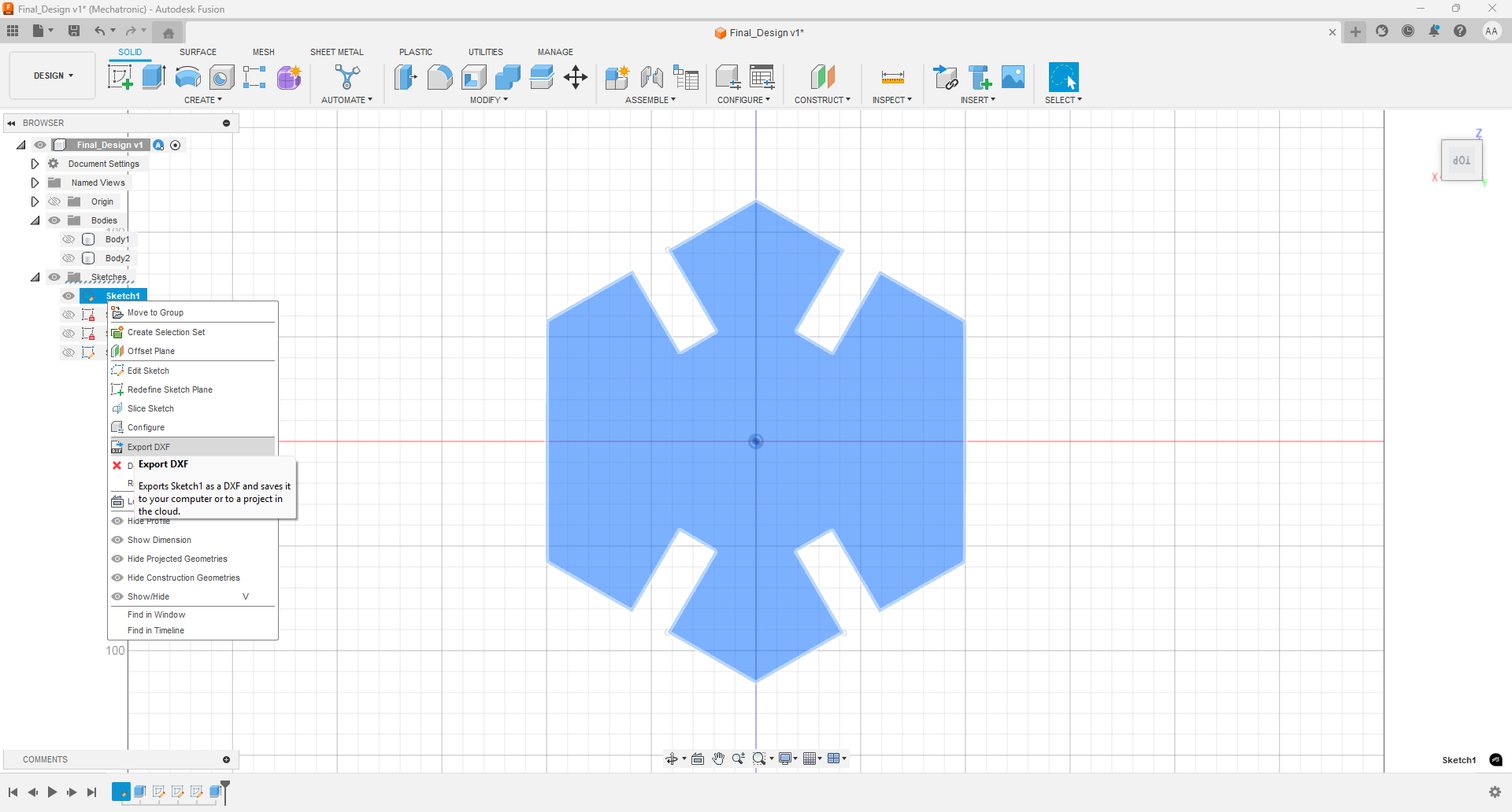
DXF file generation
With the letter p in the drawing, the projection of the drawing is performed and associated drawings are generated which can be exported as DXF which is the format with which the laser cutter works.
After making the cuts I realized that when I scaled the design in lightburn I didn't have the aspect ratio locked and what should look like a hexagon didn't look like a hexagon.
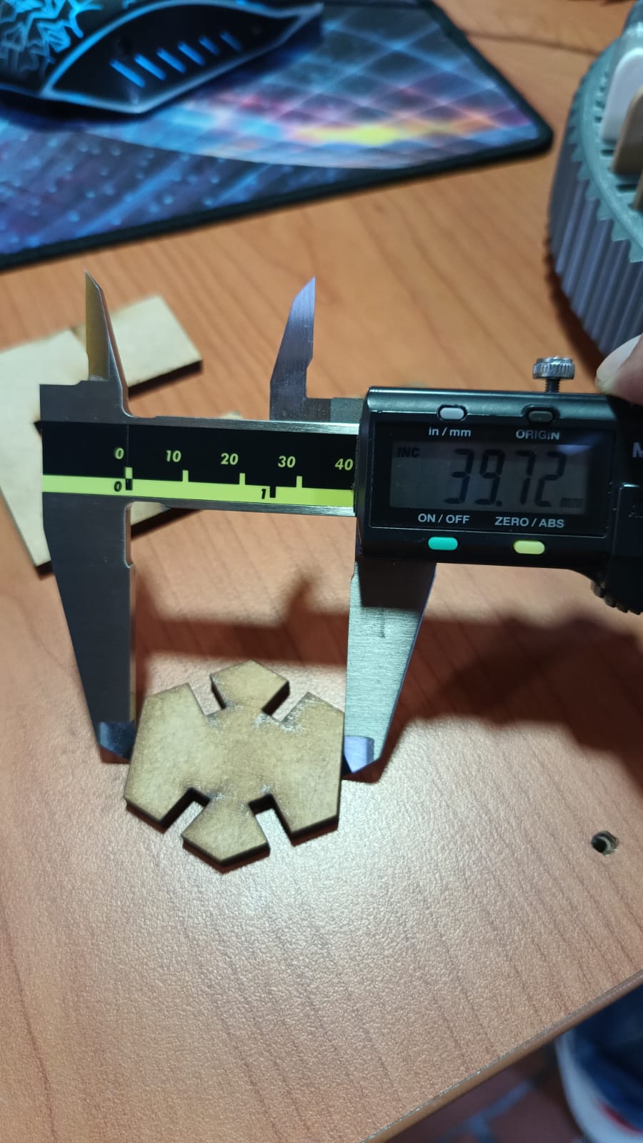
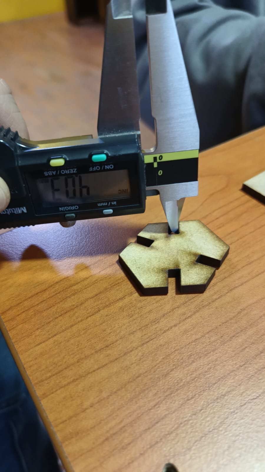
After making the respective corrections and modifying the design, I cut on the machine a design that did not need to be scaled and that met my thickness expectations according to the material size of 3 mm.
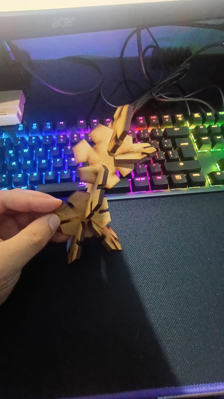
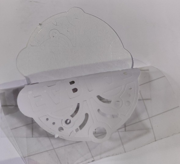
Finally, my first parametric kit is composed of hexagonal pieces with 6 slots that you can join in different ways to represent more familiar figures like in this case a person or a giraffe.
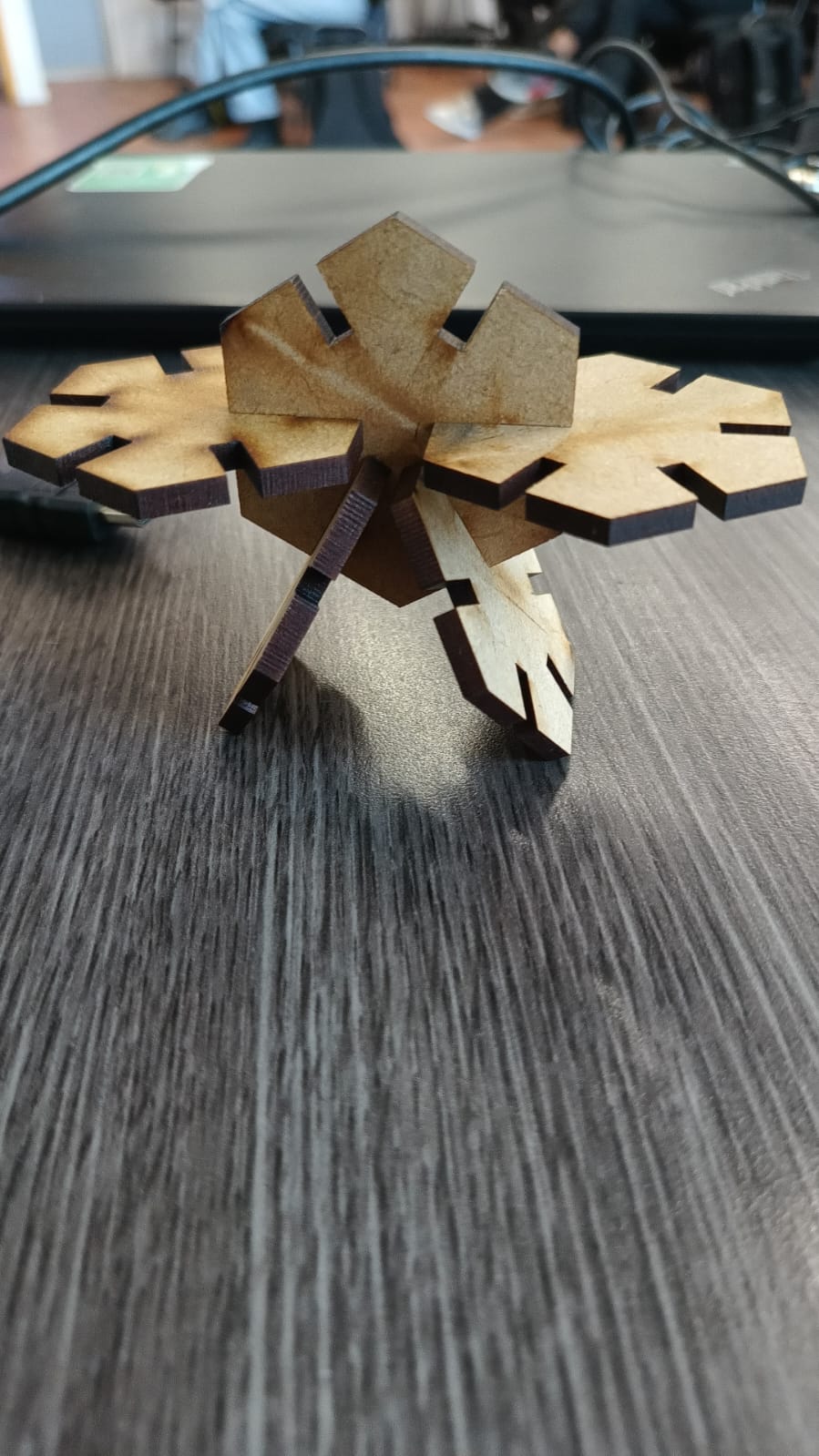
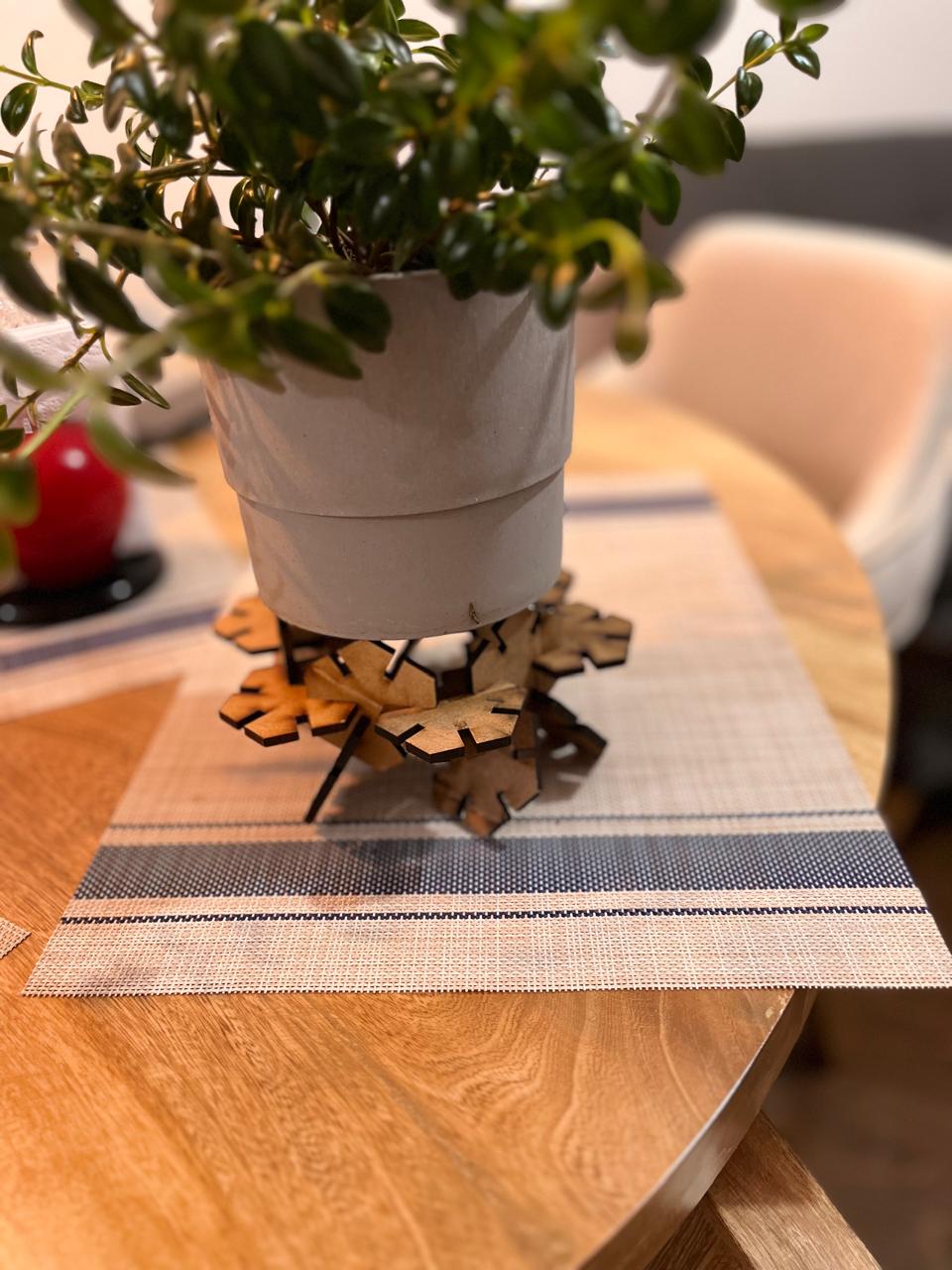
One of the first alternate constructions was a plant stand. The pentagonal pieces were assembled in a stable circular base that elevates and supports a flowerpot. This demonstrates the structural strength and balance achievable with the kit.
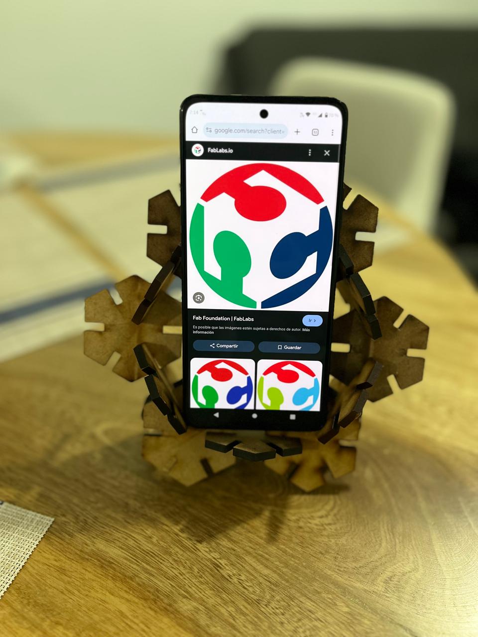
A two-part assembly was created as a smartphone stand. This view shows how the front modules hold the device upright, with sufficient grip and space for the screen to remain fully visible.
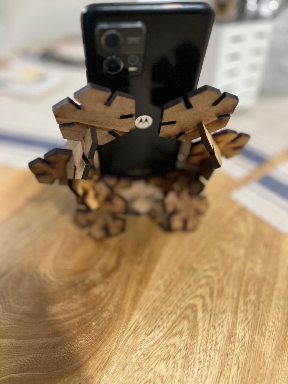
From the back, the support structure can be appreciated in more detail. The pentagons lock into each other to generate both vertical and angular stability for the phone.
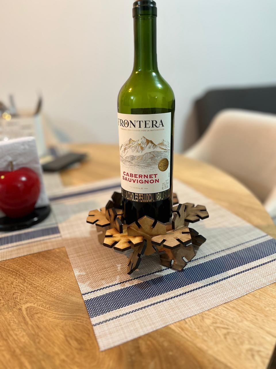
Finally, the construction kit was used to create a decorative and functional wine bottle holder. The symmetry of the pentagons forms an elegant and modern base that perfectly cradles a standard bottle.
Working with the Vinyl Cutter: Cricut Maker 3
In this section, I describe the step-by-step process I followed to cut a vinyl design using the Cricut Maker 3. I used Cricut Design Space software and transferred a vector logo to vinyl using a mirror cut. Below is the complete workflow from software setup to material transfer.
Installing Cricut Design Space
I downloaded the Cricut Design Space software from design.cricut.com and installed it on my computer. After logging in, I created a new project on a blank canvas.
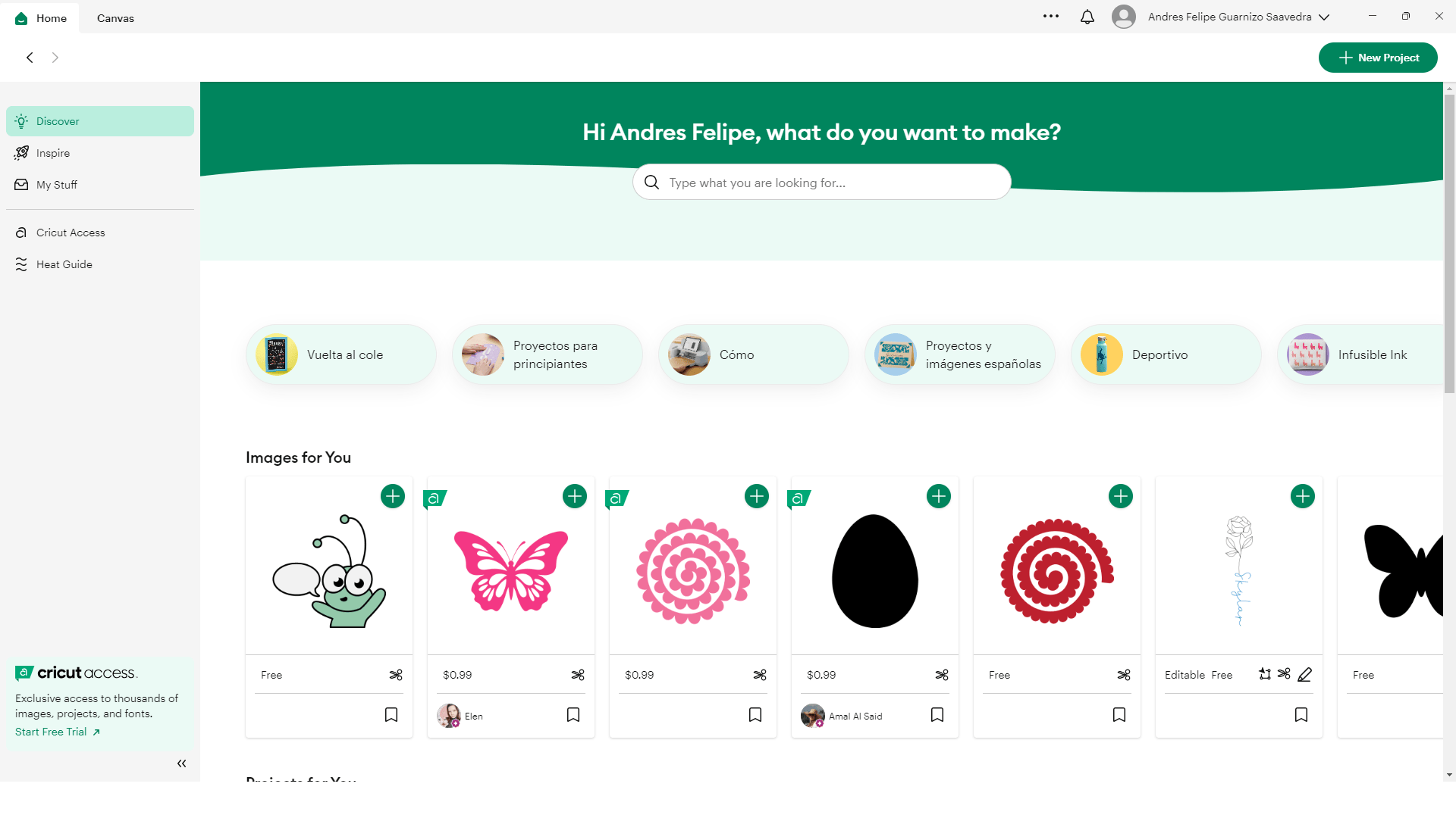
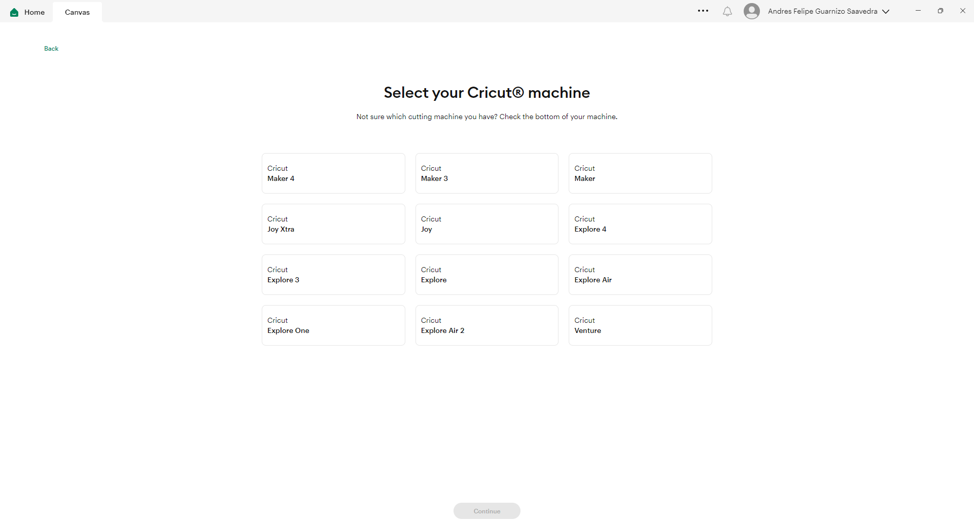
Configuring the Workspace
I selected the Cricut Maker 3 as the machine. The left panel of the workspace allowed me to use tools such as Shapes, Text, Images, and Upload. The top menu offered options for size, alignment, and color.
Uploading and preparing the Design
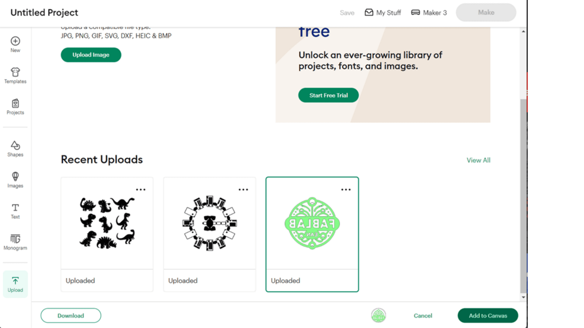
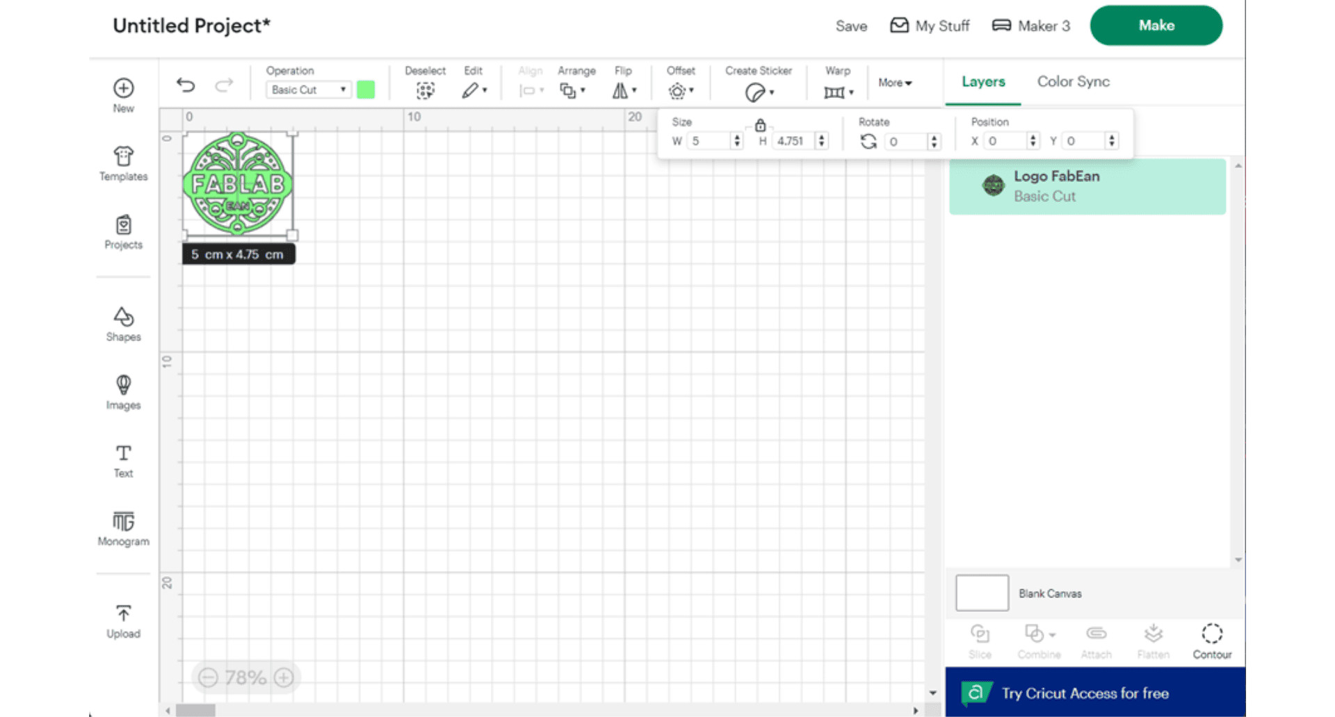
When creating a new project, a blank workspace will open up with the different tools on the left side. It is important to select the machine with which you are going to work, in this case the Cricut Maker® 3. By selecting the upload option you can upload the files you are going to work with, preferably vectors. Select the vector with which you want to work, in this case I selected the fablab logo, you can see that the workspace allows you to save the different files with which you have worked.
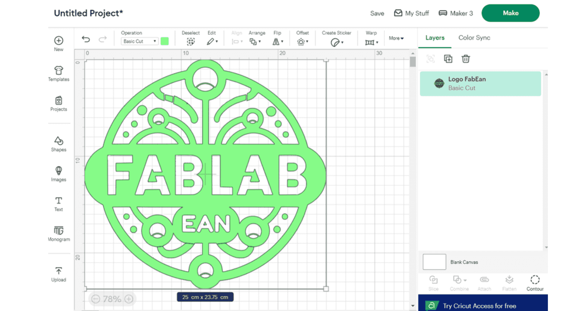
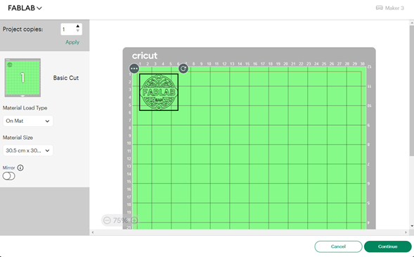
After performing the operation the vector is already in the right direction, here you can see the dimensions in the lower part of the vector, you must adjust it to the desired size, in the upper part you will find the option more.
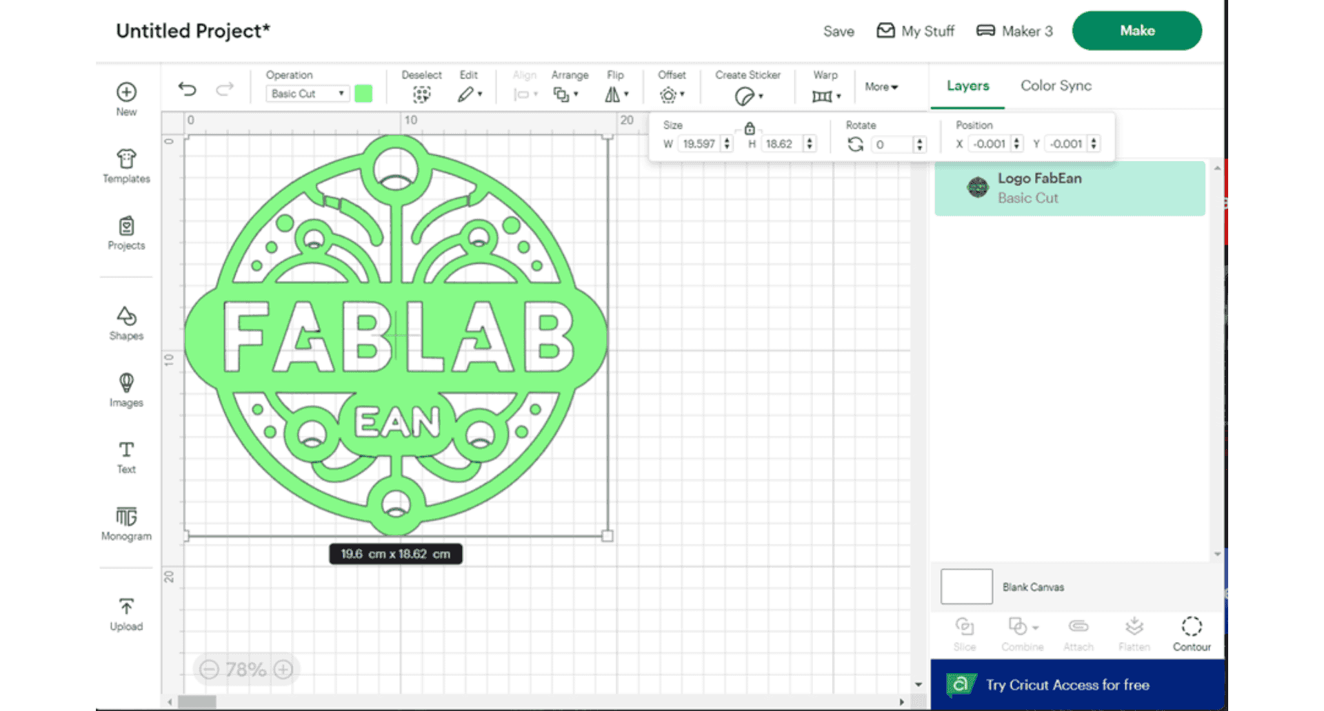
Selecting the more option displays the options of dimension, position and rotation, in the dimension you can change the size in units (cm), it is important to highlight the padlock which means that the relationship between height and width is maintained, you must adjust the vector in the part that you want to be cut in the vinyl.
After the corresponding changes have been made, the machine can be configured for cutting.
Configuring the machine and workspace
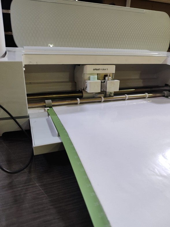
The area must be prepared for correct operation: it must be free both in front and behind so that the vinyl can move freely during the operation. The machine must be connected to the power supply and, in turn, the computer on which the program is created must be connected.
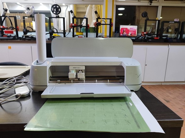
Once the space has been tidied up, the Cricut Maker 3 is turned on with the power button, which will light up white if everything is working properly. Once turned on and connected we select the make option to start. After saving the project, select the surface to work with.
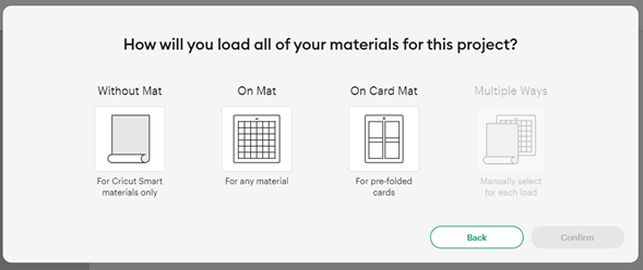
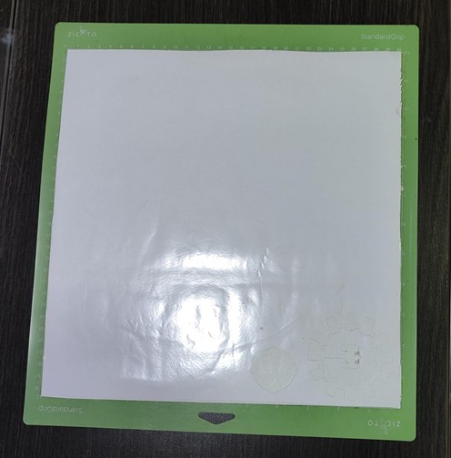
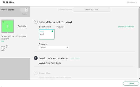
In this case, I used On mat measuring 30.5 x 30.5 cm. They are also available in other dimensions.
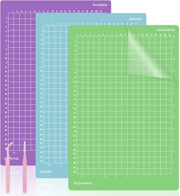
The surface is prepared with the material to be used, the glue protection is removed and the material is placed making sure that it is aligned with the predetermined grid for the project.
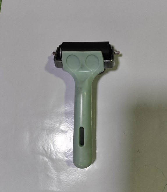
With the help of the roller included in the machine kit, it is ensured that all the material is correctly adhered to the plate, no corner or edge can be left lifted.
After selecting the surface, make sure that the project is within the limits of the cut, which are framed in red, you can place the cut anywhere on the plate.
After configuring the cut, it must be connected to the machine using the cable, this process is fully automatic, so it is important to have selected the machine model properly.
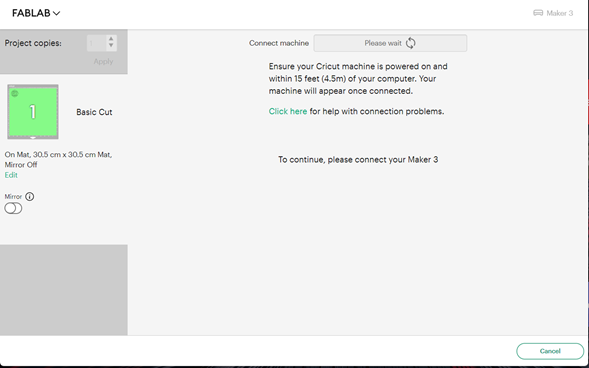
When connecting you select the material to be used, in this case I selected vinyl and in the pressure option I selected the more option, I selected the appropriate material from the entire library available, taking into account that it can be configured in much more detail in the settings option.
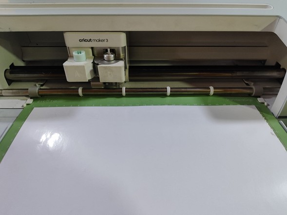
After selecting the material correctly, the material should be placed in the tray of the cricutmake3. It is important to check that both the plate and the material are placed under the tabs that hold them at the edges and make contact with the main roller.
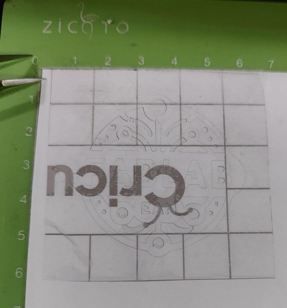
After placing the material correctly, press the button as indicated in the instructions to start the cut, and it is also possible to monitor the progress.
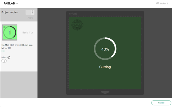
First the material will be rolled to the rear, a calibration of the horizontal axis will be performed and the cutting will start. Here you can see the cutting process.
Once the cutting is finished, using the tools in the kit, the surplus or those parts that do not fit in the final result are removed. After leaving the final vinyl I used transfer paper which I cut to the size of the cut and glued it on top of the vinyl with enough pressure so that the parts were transferred, so that when I lift it up the cut remains on the transfer and I can paste it on any surface.
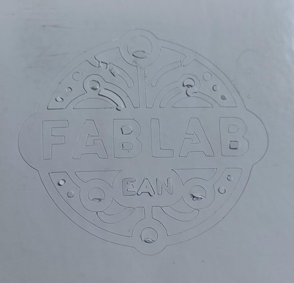
Finally, I placed the logo on an opaque surface to see the detail. I learned that I should generate the cuts better in the program since the letters “B” did not look very good.