Week 2
Computer-Aided Design
Summary of Activities
During this week, the focus was on exploring different 2D and 3D modeling tools to develop a preliminary version of the CanSat project. The objective was to evaluate and compare vector and raster-based software for 2D design, as well as test basic 3D modeling techniques using AutoCAD and SolidWorks. Additionally, image and video compression methods were applied to optimize the documentation process. Through these exercises, a structured digital representation of the project was developed, laying the foundation for future prototyping and design refinements.
2D Design
INKSCAPE
AInkscape is very useful for converting a drawing into a set of vectors and easily modifying designs.
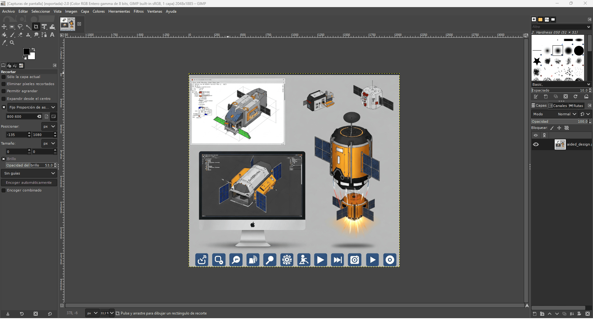
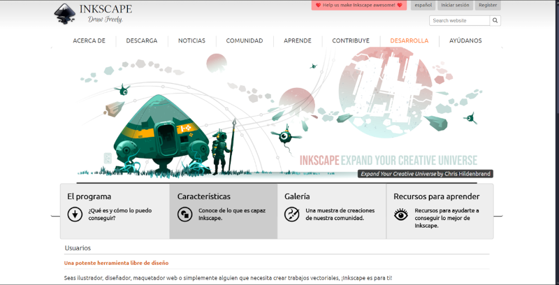
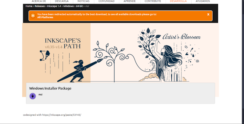
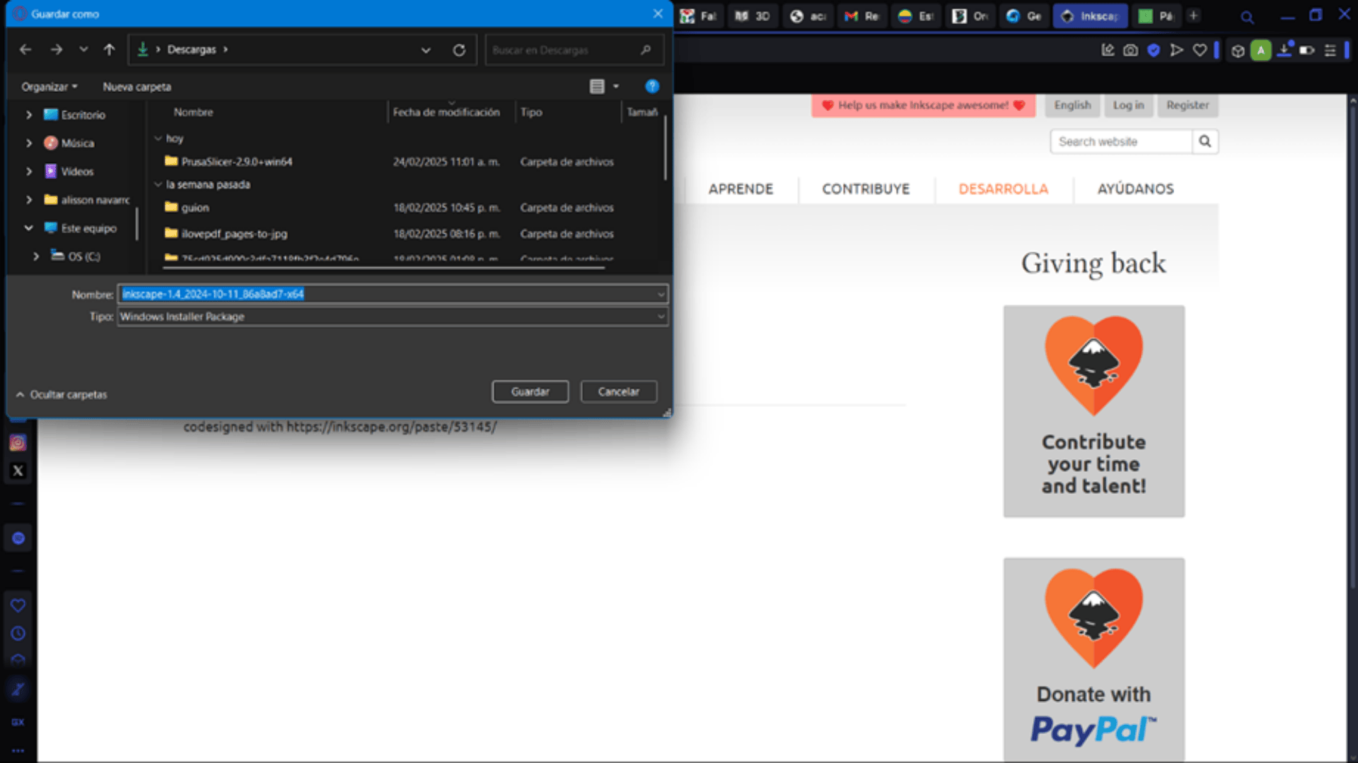
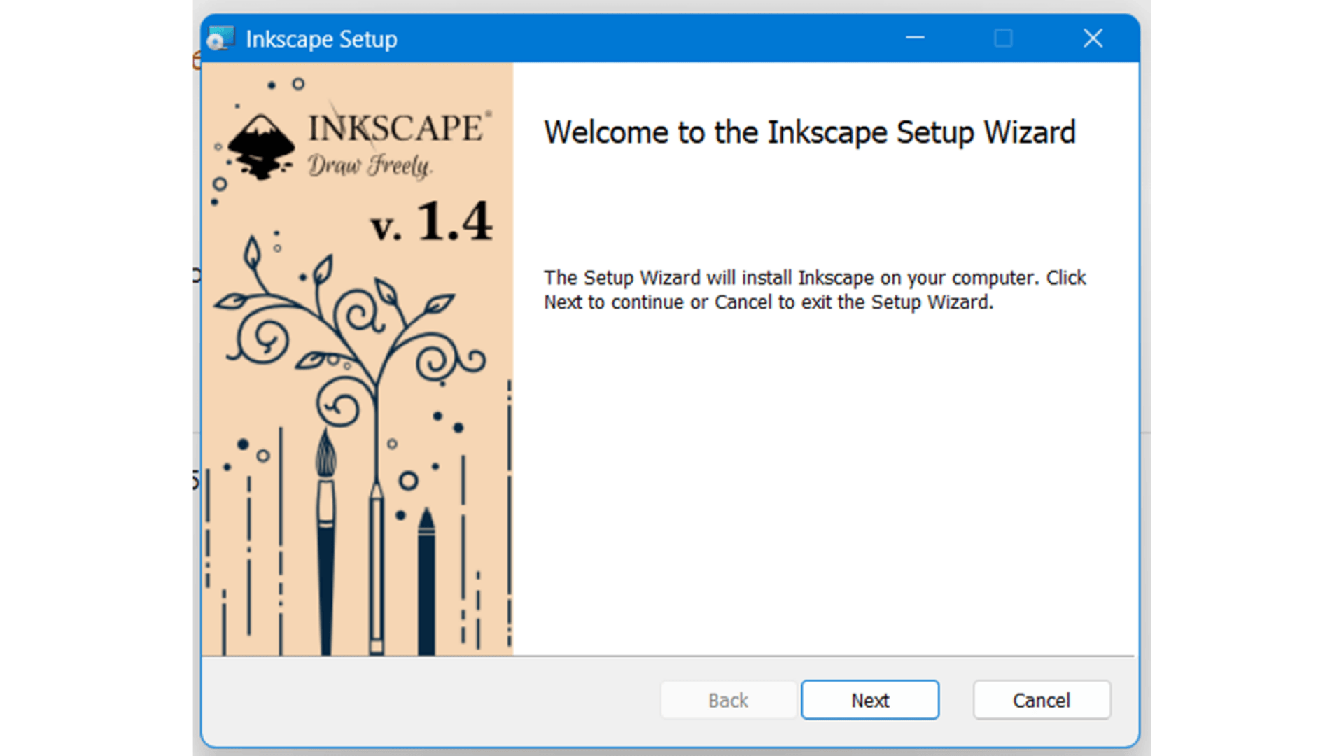
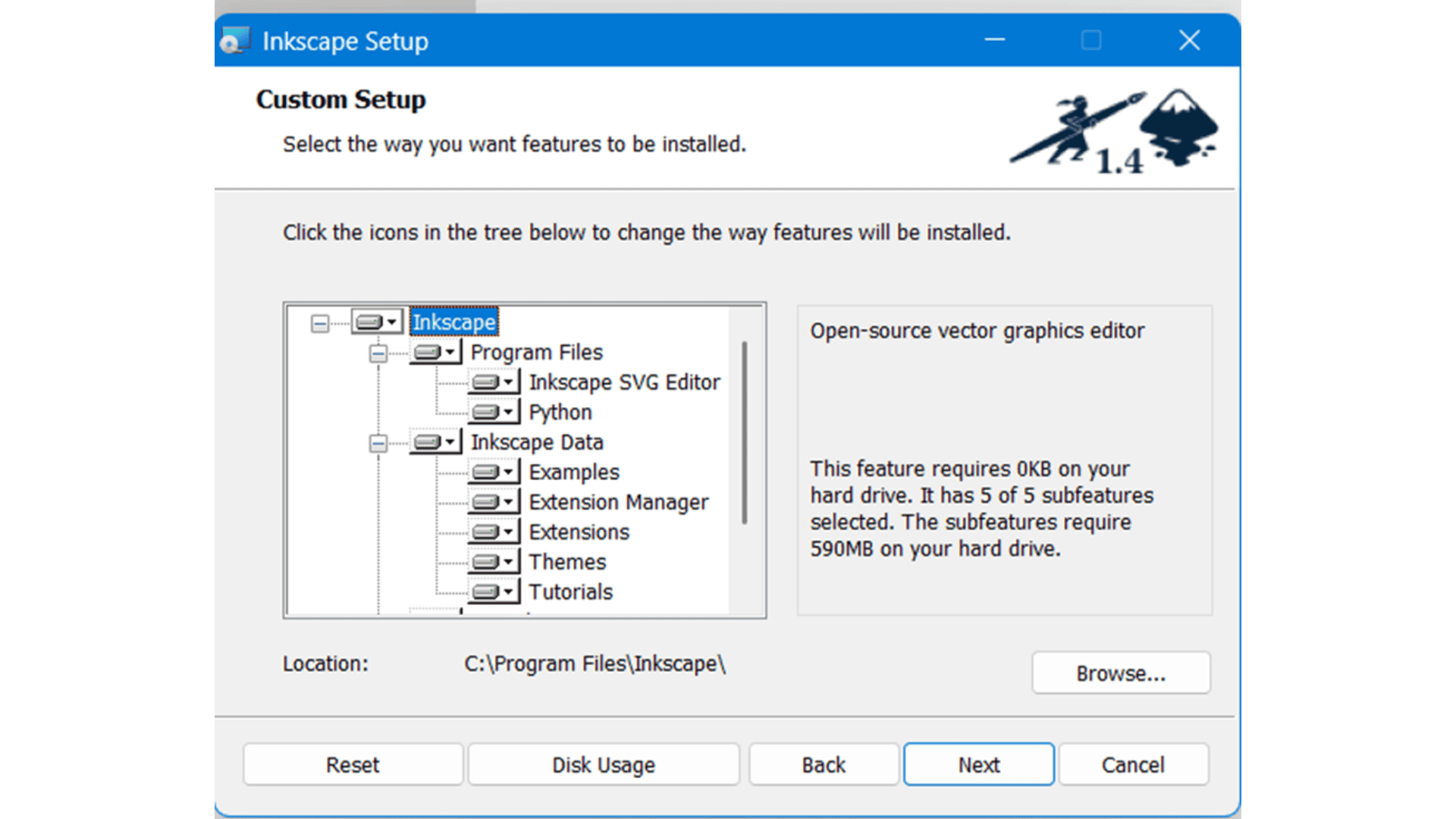
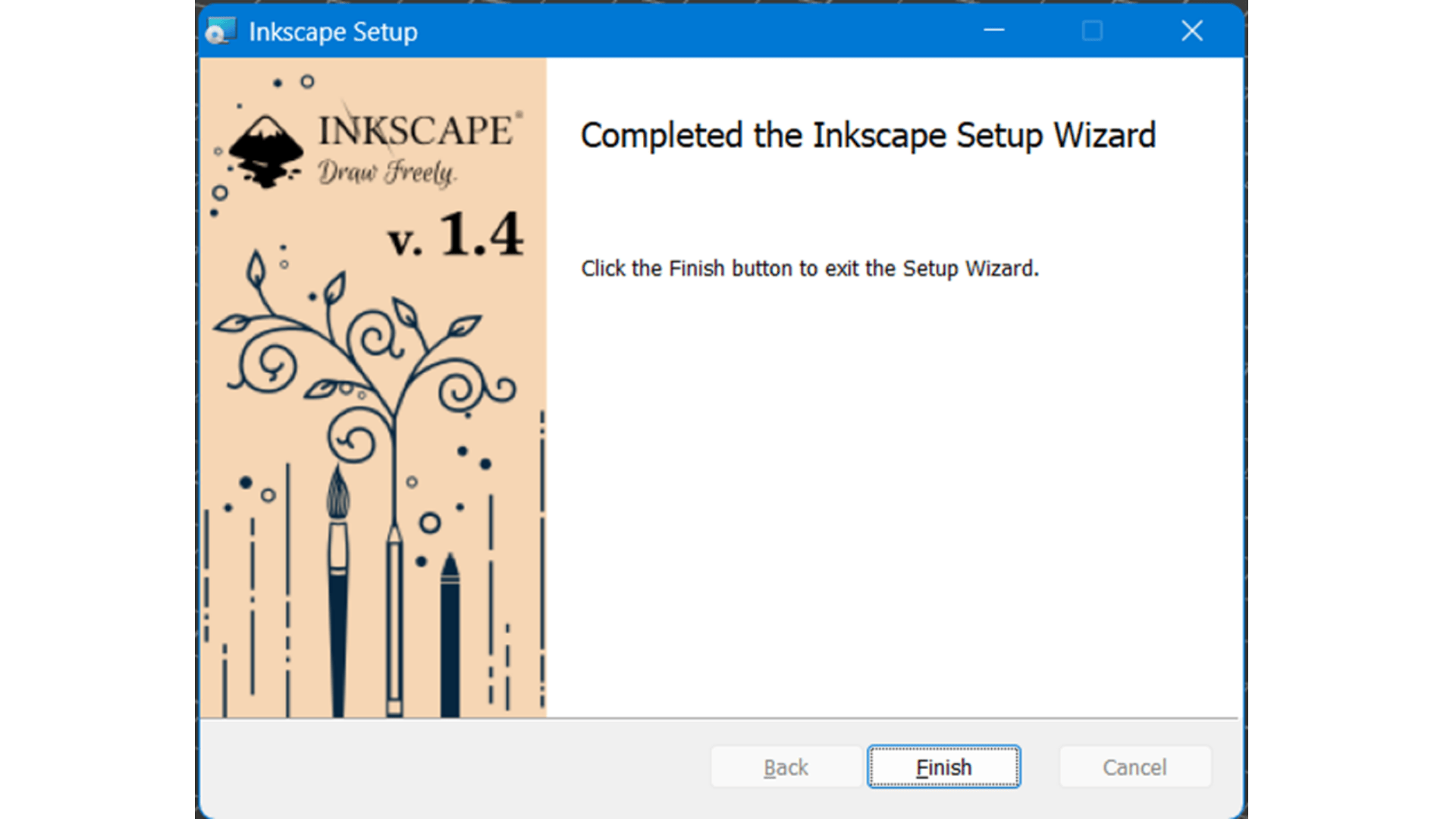
The installation process is detailed below, taking into account that for all images an image
compression process has been used through GIMP software.
Importing an Image
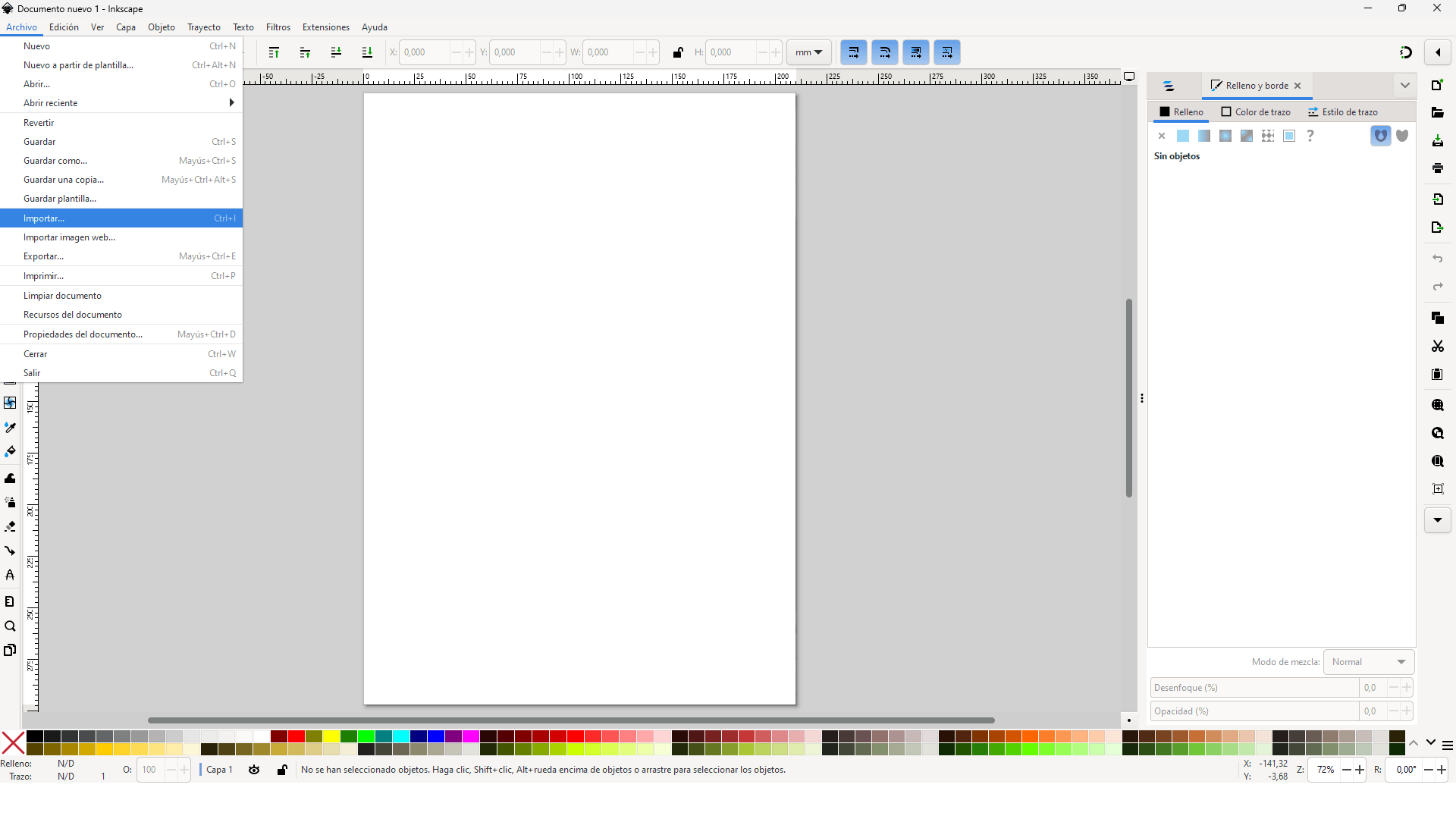
The first step involves importing the raster image into Inkscape. Once imported, the image can be resized and positioned accordingly.
Converting to a Vector
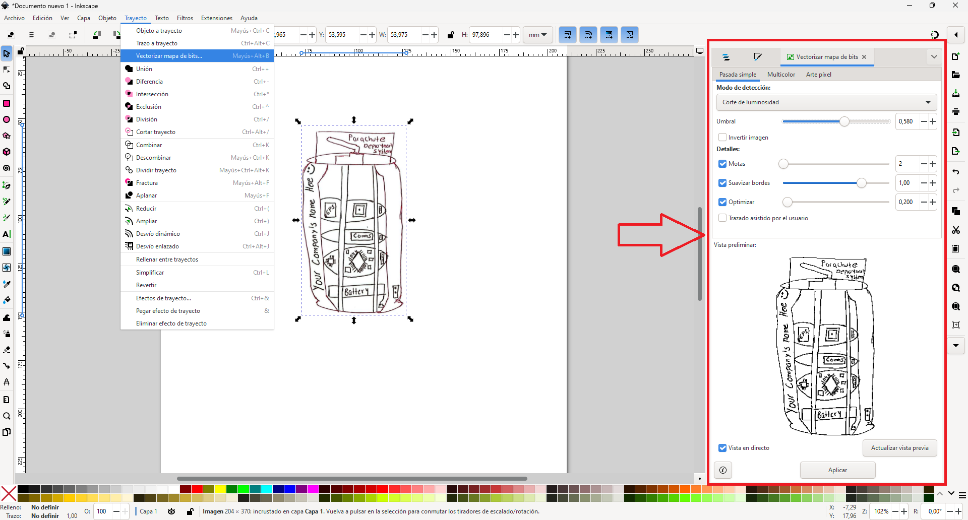
To transform the image into a vector, Inkscape provides a Trace Bitmap function, which offers multiple tracing methods. Users can adjust brightness and threshold levels to optimize the output.
Using the "Trace Bitmap" Tool in Inkscape
The red highlighted section in the image represents the "Trace Bitmap" tool in Inkscape, which allows users to convert raster images (such as PNG or JPG) into vector graphics. This feature is useful for transforming hand-drawn sketches, logos, or low-resolution images into scalable vector designs.
What You Can Do with This Panel
- Detection Mode: The mode selected is "Brightness Cutoff", which detects edges based on brightness levels in the image. Darker areas will be traced as solid vector paths, while lighter areas will be ignored.
- Threshold (Umbral): The slider allows you to adjust the sensitivity of the detection. A lower value traces only the darkest regions, while a higher value captures more details.
- Details Options:
- Speckles (Motas): Removes small noise from the tracing process, making the result cleaner.
- Smooth Edges (Suavizar bordes): Softens the edges of the traced image, reducing jagged lines.
- Optimize (Optimizar): Helps reduce the number of nodes, making the vector output smoother and easier to edit.
- Preview Window (Vista Preliminar): Displays a real-time preview of how the image will be traced based on the selected settings.It's possible toggle "Live Preview" (Vista en directo) to update the results dynamically before applying the changes.
- Apply Button (Aplicar): Clicking "Apply" converts the raster image into a vector object. The newly created vector can be resized, edited, or used in CAD/CAM applications without losing quality.
Editing the Vector
Once vectorized, the object can be further edited using the Node Tool, which allows precise control over curves and shapes.
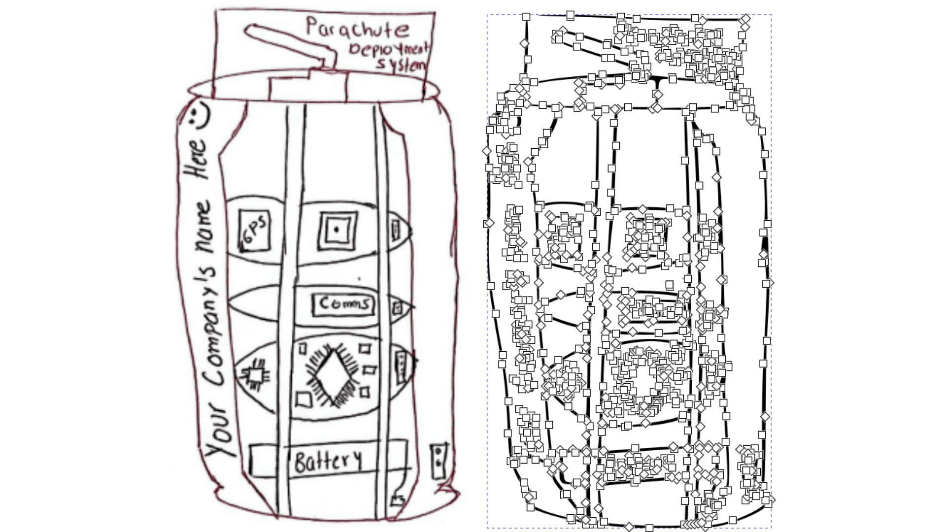
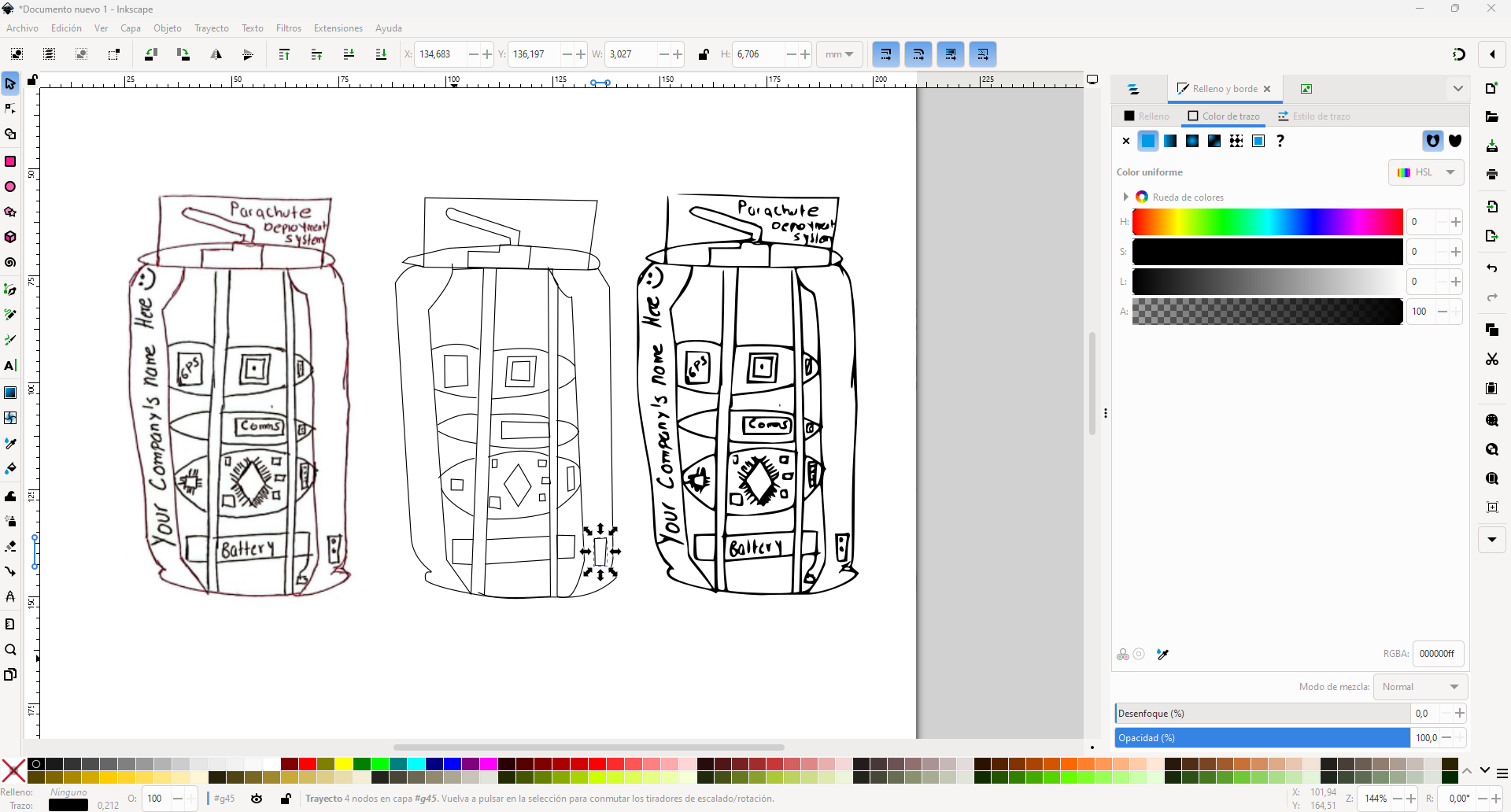
It is possible to draw the lines of the drawing by hand using the pen tool on the left side of the image below, however, as can be seen in the center image it is more difficult to trace details and shapes as well as more time consuming. On the right side it is possible to adjust the thickness of the stroke and the fill should be removed since no solid figure is needed for the actual drawing, it is also important to have the opacity at 100%.
Exporting the Vector
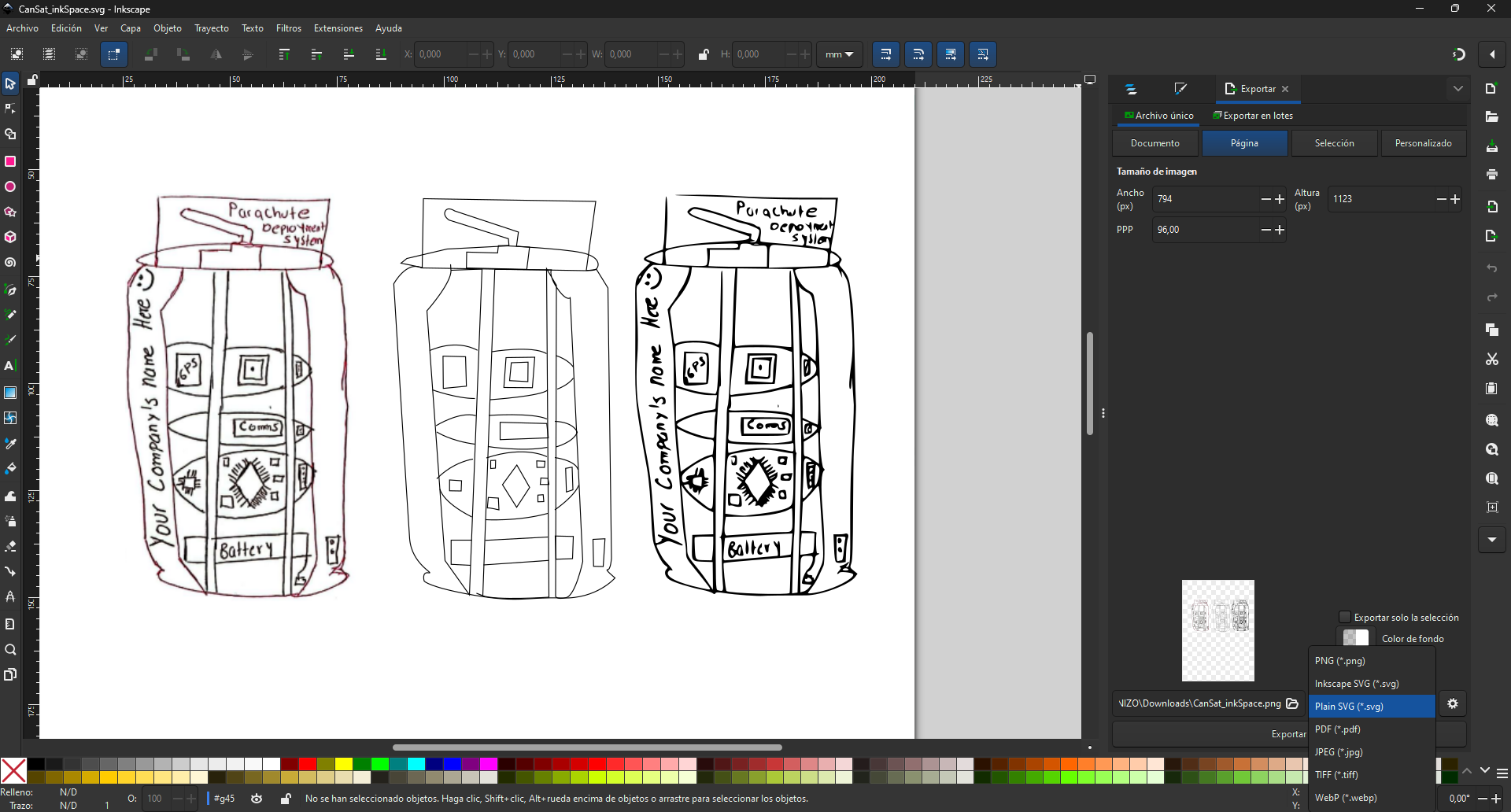
Finally, the vector file is saved in an appropriate format such as SVG, PNG, JPG OR PDF for further use.
Vectorization in XTool Creative Space
XTool Creative Space is a tool built specifically for laser engraving and cutting, making it super easy to turn raster images into vector paths ready for CNC or laser processing. Unlike Inkscape, which is a more general-purpose vector editor, XTool is streamlined for fabrication, helping users quickly set up designs without the extra steps. It's a practical choice when the goal is to move straight from concept to production.
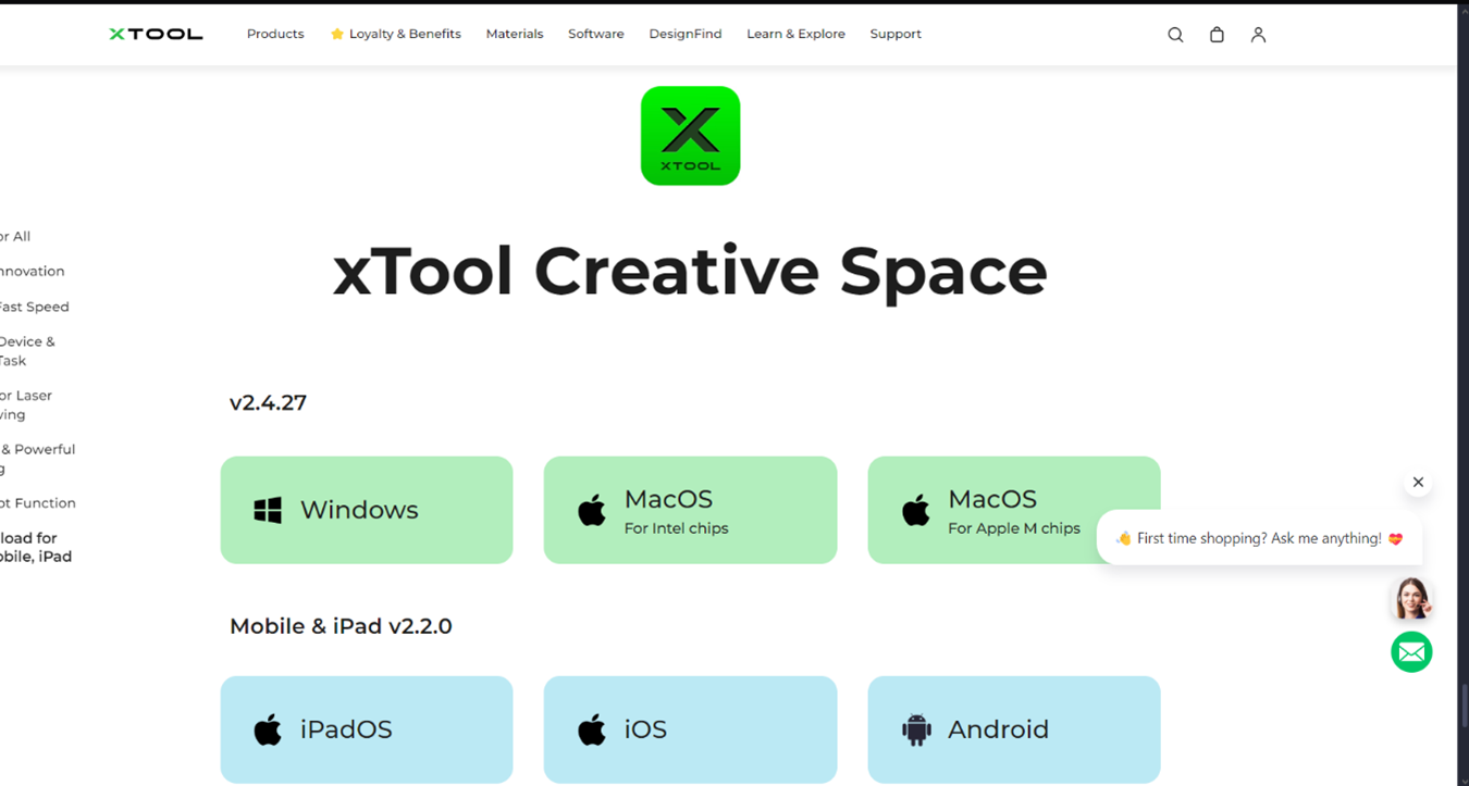
Download and install the software
To illustrate the process of downloading and installing the xtool software I followed the recommendation of my colleague Jhonatan Cortes to incorporate bootstrap in my template and create a different way of presenting images.
Vectorization Process
Step 1: Open XTool Creative Space
Launch XTool Creative Space on your computer. You will see an empty workspace with a grid layout. Navigate to File > New to start a new project.
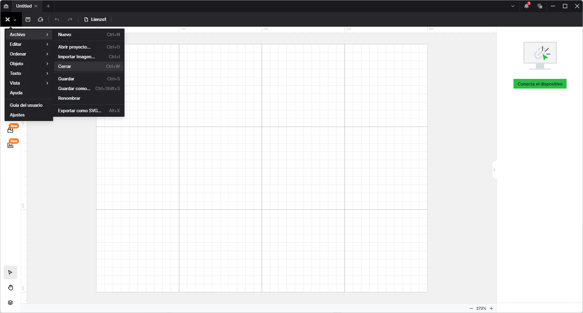
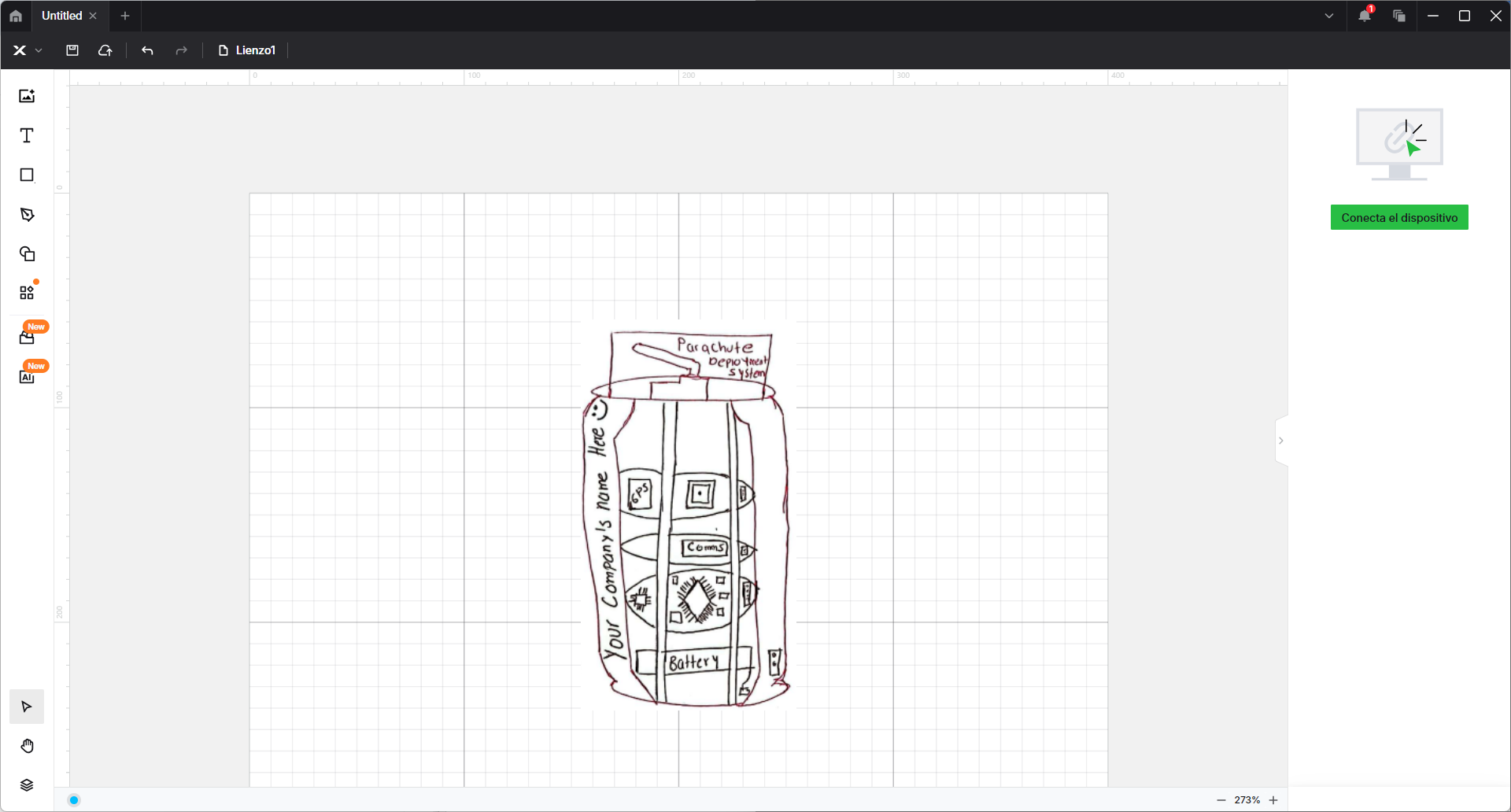
Step 2: Import the Hand-Drawn Image
Go to File > Import Image... or use the shortcut Ctrl+I. Select the hand-drawn sketch you want to vectorize. The imported image will appear on the grid, where you can resize or reposition it.
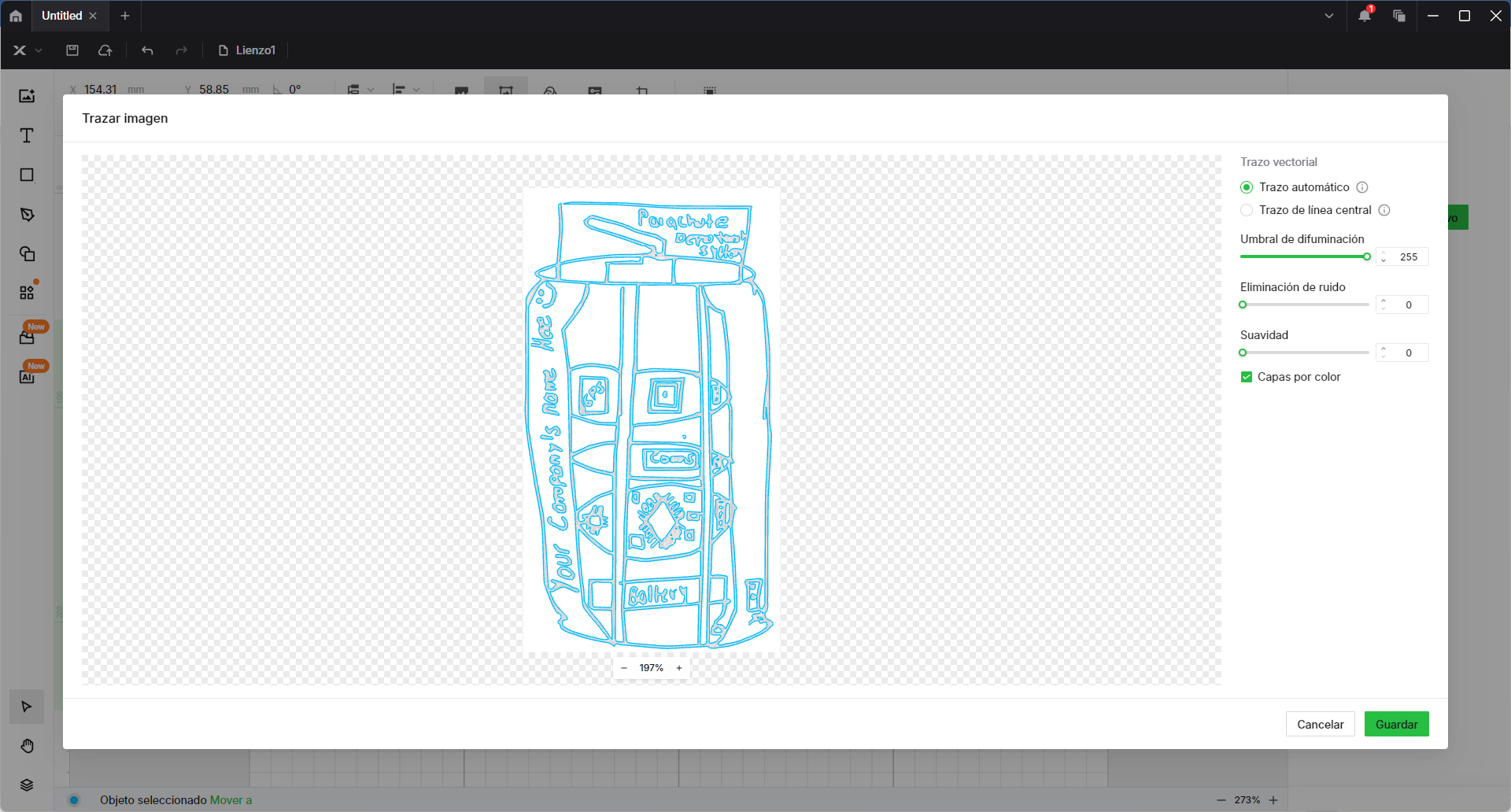
Step 3: Open the Vectorization Tool
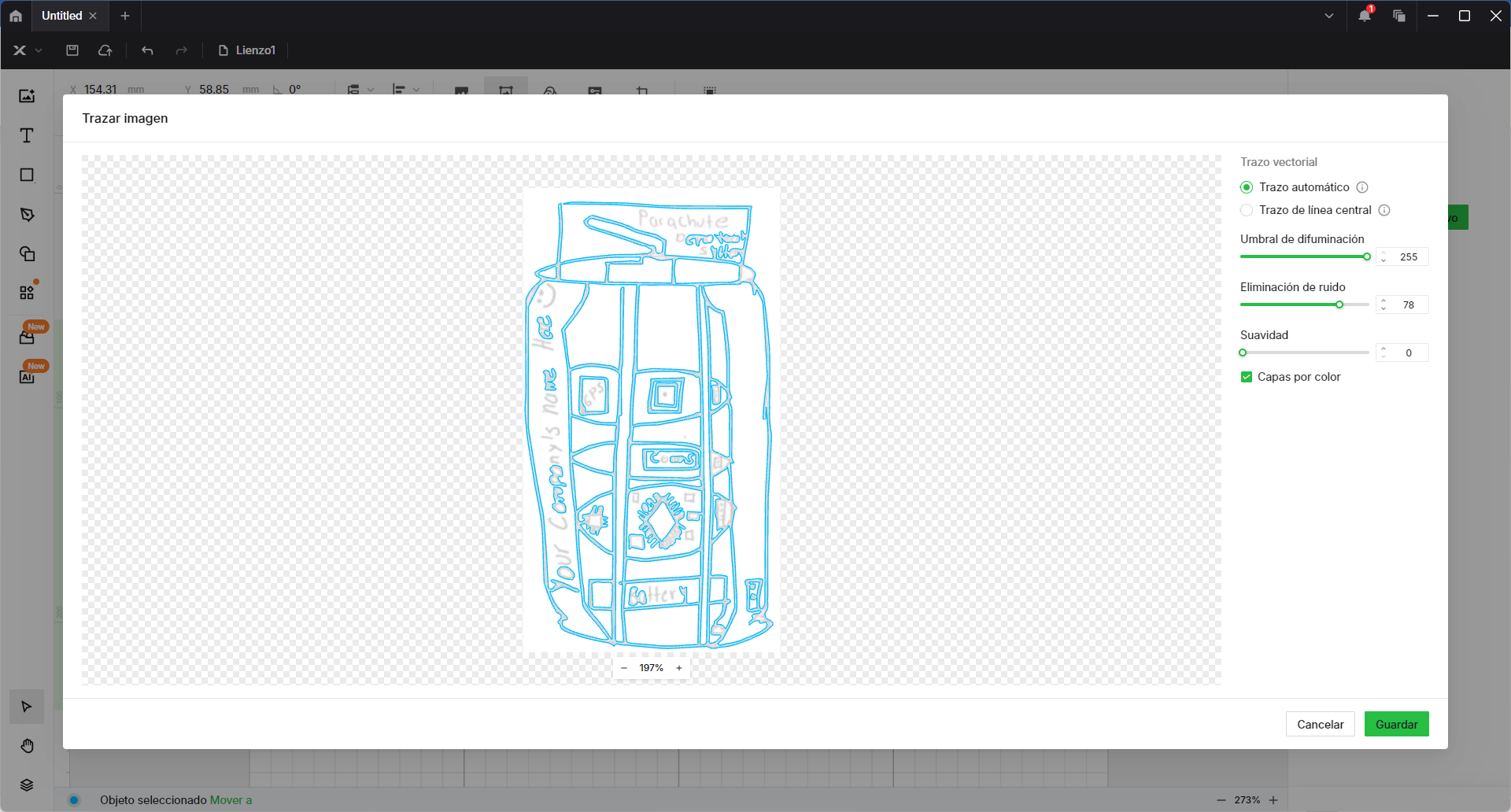
With the image selected, navigate to "Trace Image". This option allows XTool Creative Space to analyze the bitmap image and generate vector outlines.
Step 4: Adjust Vectorization Settings
In the Trace Image panel, you will see different settings that control how the vector paths are generated:
- Blur Threshold: Adjusts how much detail is captured.
- Noise Reduction: Removes unnecessary small details from the vector path.
- Smoothness: Controls the curve interpolation for a cleaner result.
- Layers by Color: Helps separate different parts of the design by color.
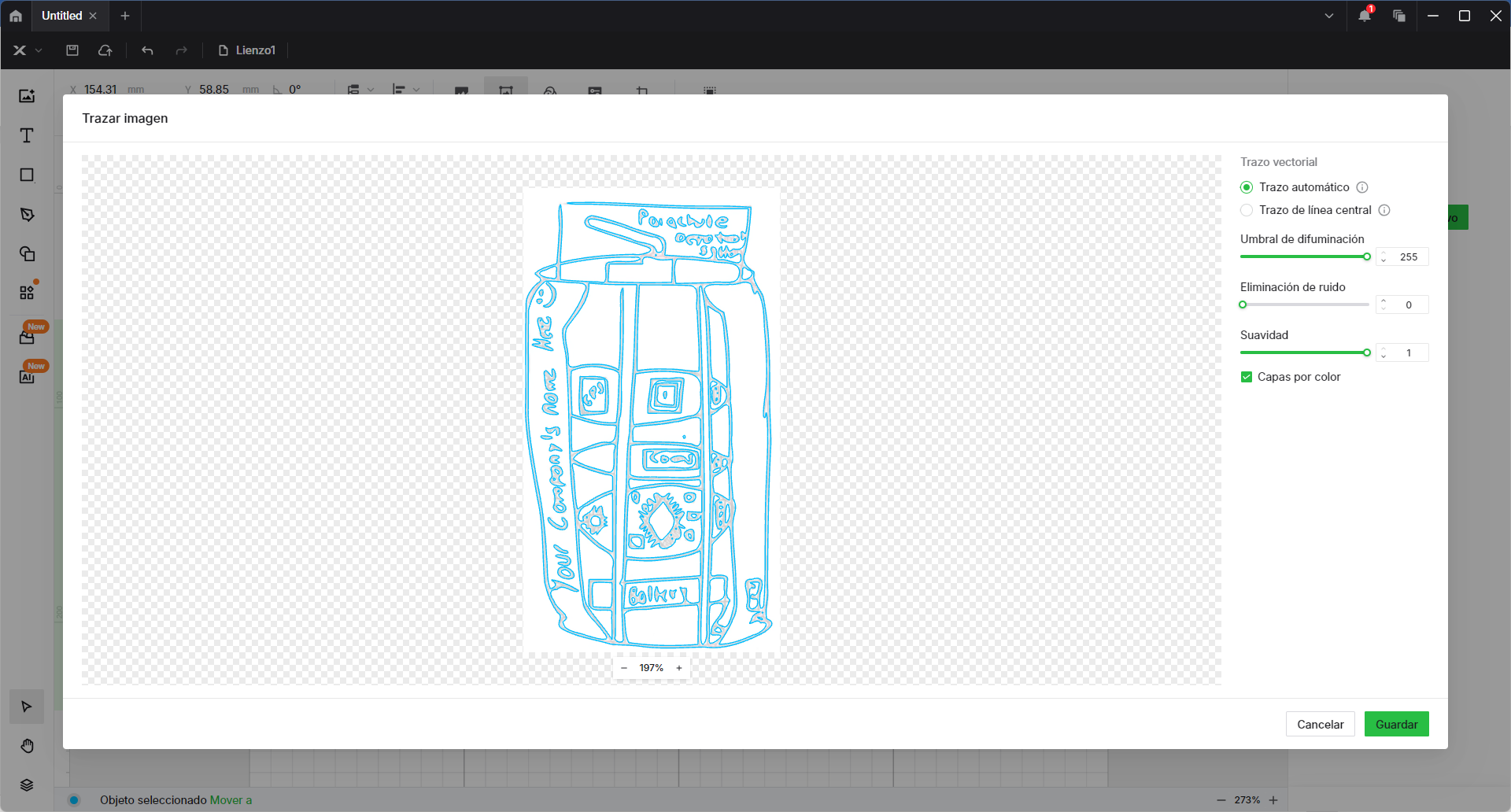
Experiment with different Noise Reduction and Smoothness values to optimize the vector quality. Click Preview to compare how each setting affects the output.
Final Result: Vector vs. Original
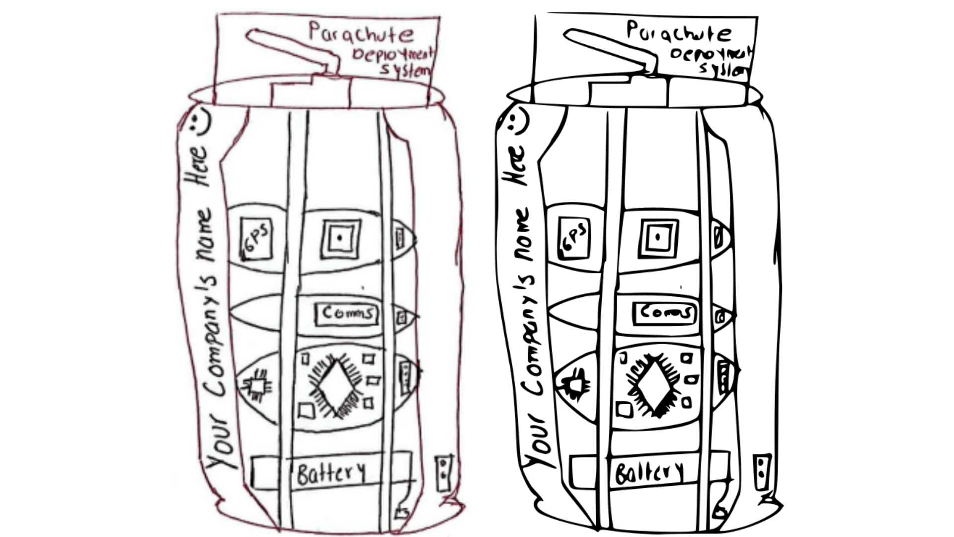
The final output consists of a comparison between the original sketch, the intermediate traced version, and the cleaned vector. This step helps visualize how the hand-drawn sketch has been optimized for fabrication.
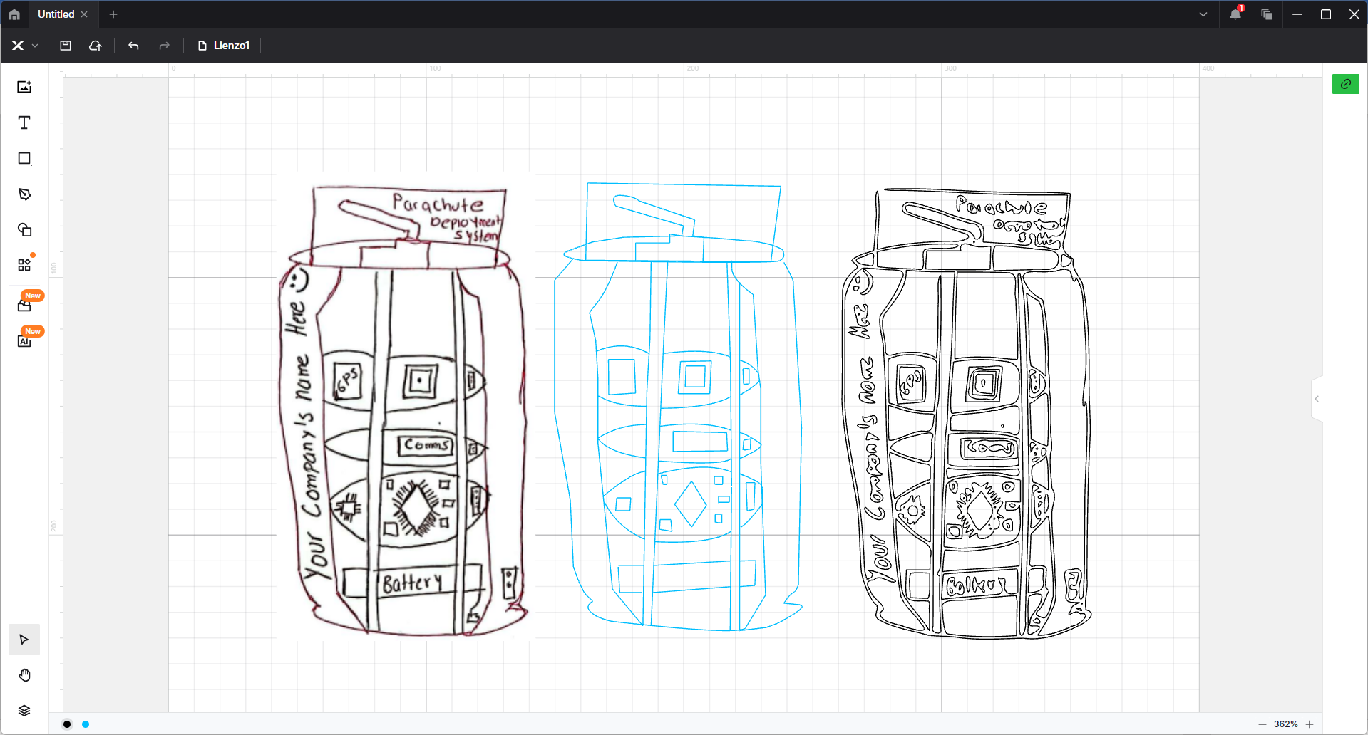
There are several challenges and problems associated with the use of this software, for example, the middle image was built using vector by vector, this functionality is similar to that of inkspace so I do not observe a noticeable difference, however, in the trace made automatically and adjusting the parameters it is observed that the trace is made to double line which makes it difficult to use to build the prototype.
3D Design
Autodesk Fusion 360: Installation and Basic Use
1. Download and Installation
To install Autodesk Fusion 360 for educational purposes, visit the official Autodesk website.
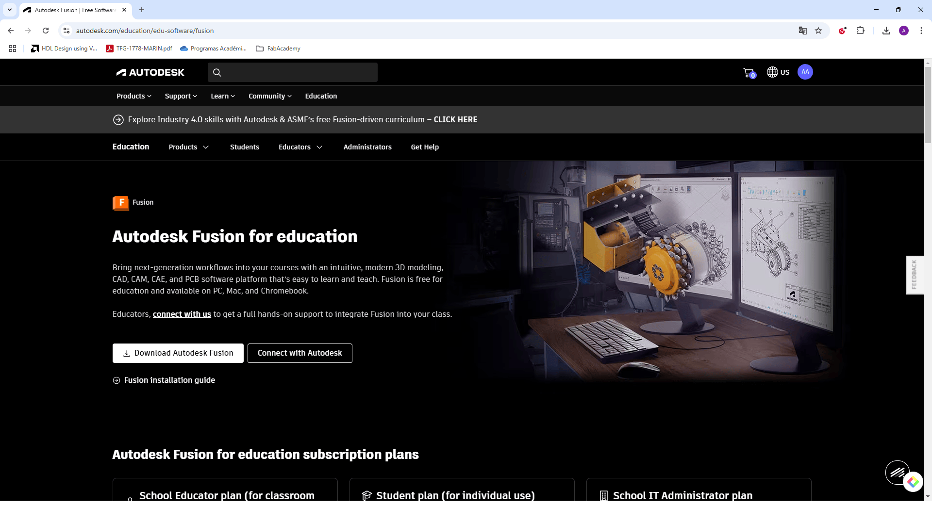
Click on "Download Autodesk Fusion" and follow the installation guide.
2. First Steps in Fusion 360
After launching Fusion 360, you will see a welcome screen with guided instructions.
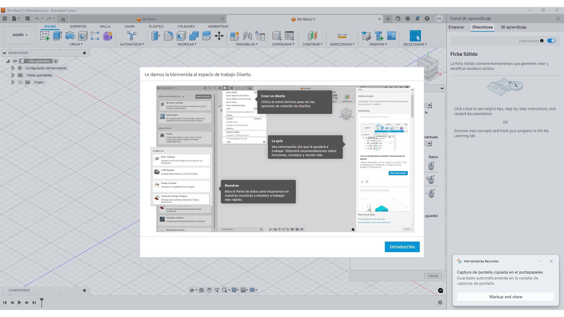
The interface includes options for creating new designs, accessing tutorials, and managing projects.
3. Creating a Basic Sketch
To start a 2D sketch, go to the Sketch tab and select a plane and use the drawing tools to create shapes like circles and lines.
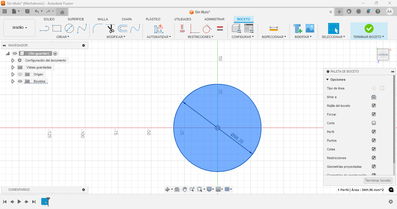
Once the sketch is ready, click Finish Sketch.
4. Extruding the Sketch
To turn a 2D sketch into a 3D model, use the Extrude tool.
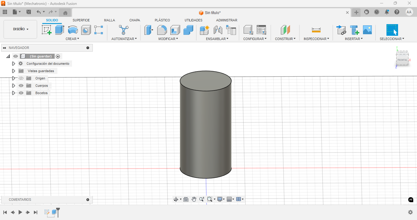
Set the desired depth and confirm the operation.
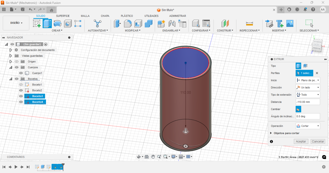
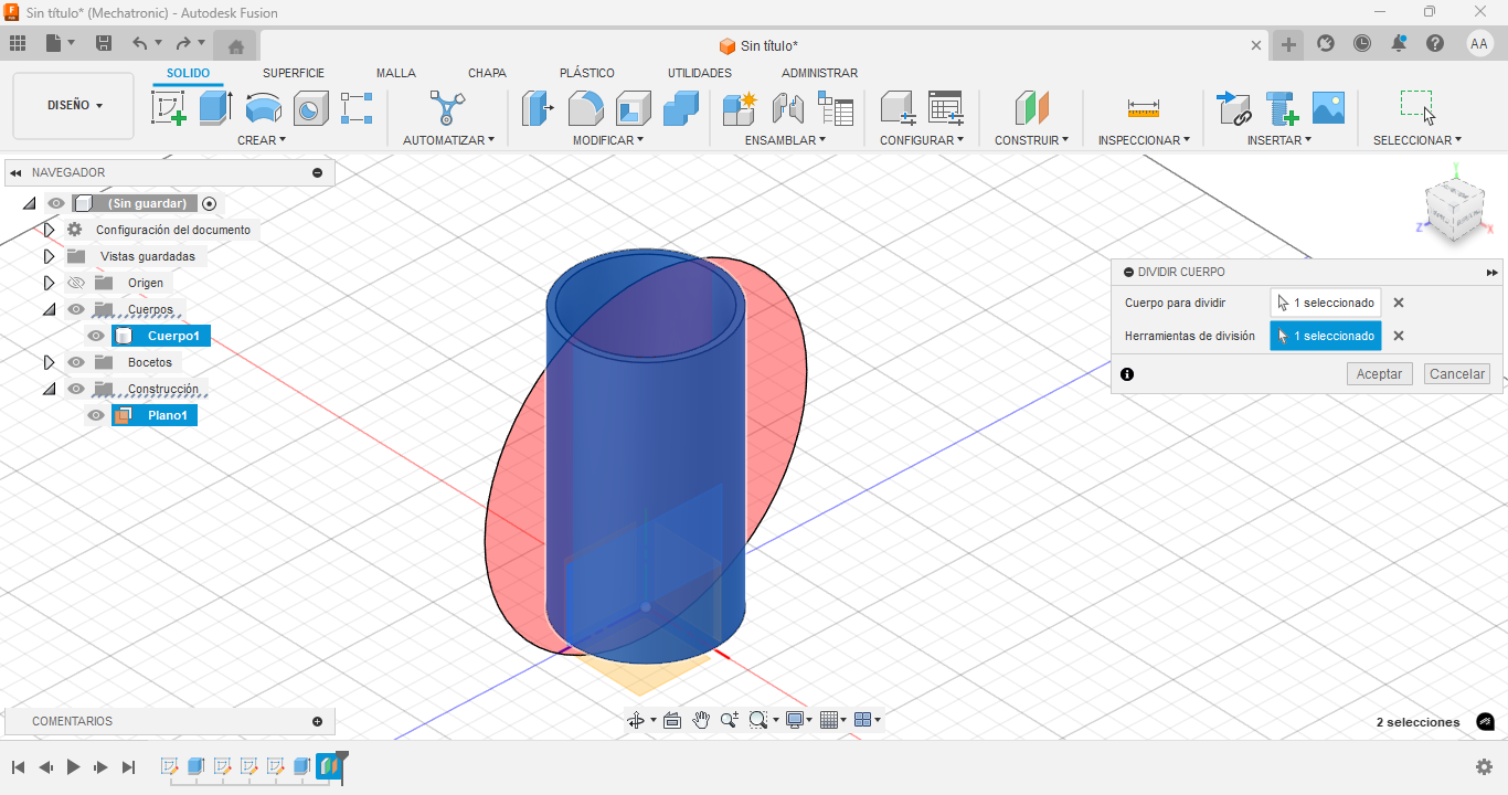
5. Split the Body
Use the Split Body tool to divide the main cylinder using the angled construction plane as the cutting tool.
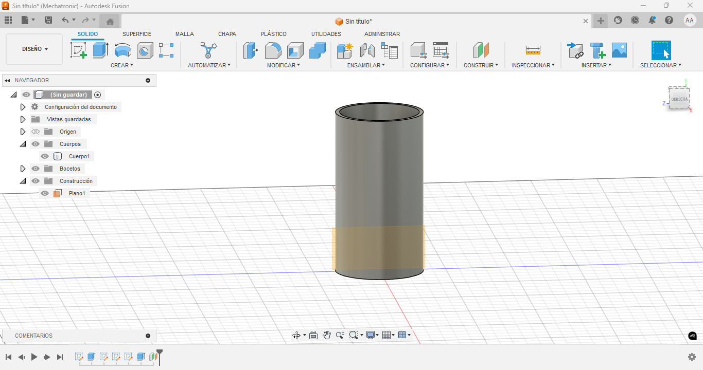
6. Body Separation
After splitting, the body is now divided into two sections. Ensure each part is properly aligned.
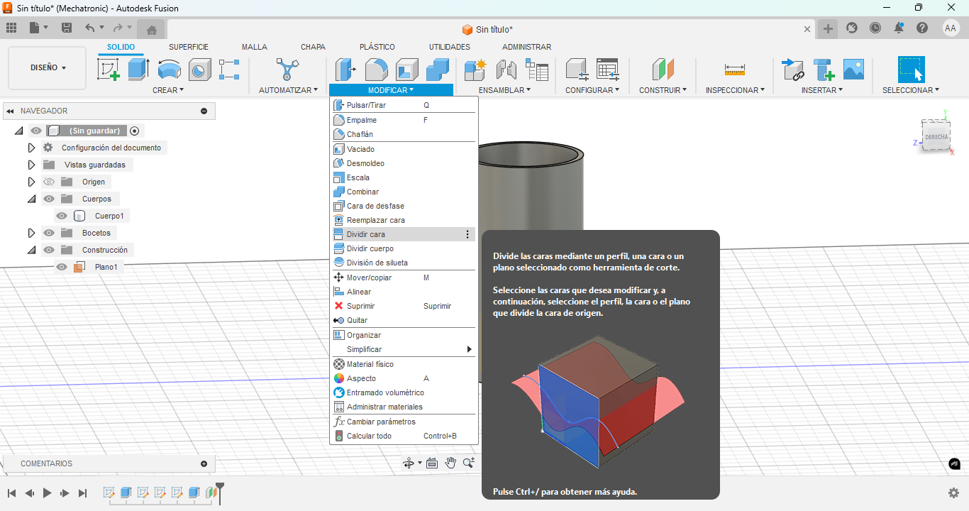
7. Adding Fasteners
Insert bolts or other fasteners into the holes to visualize the final assembly.
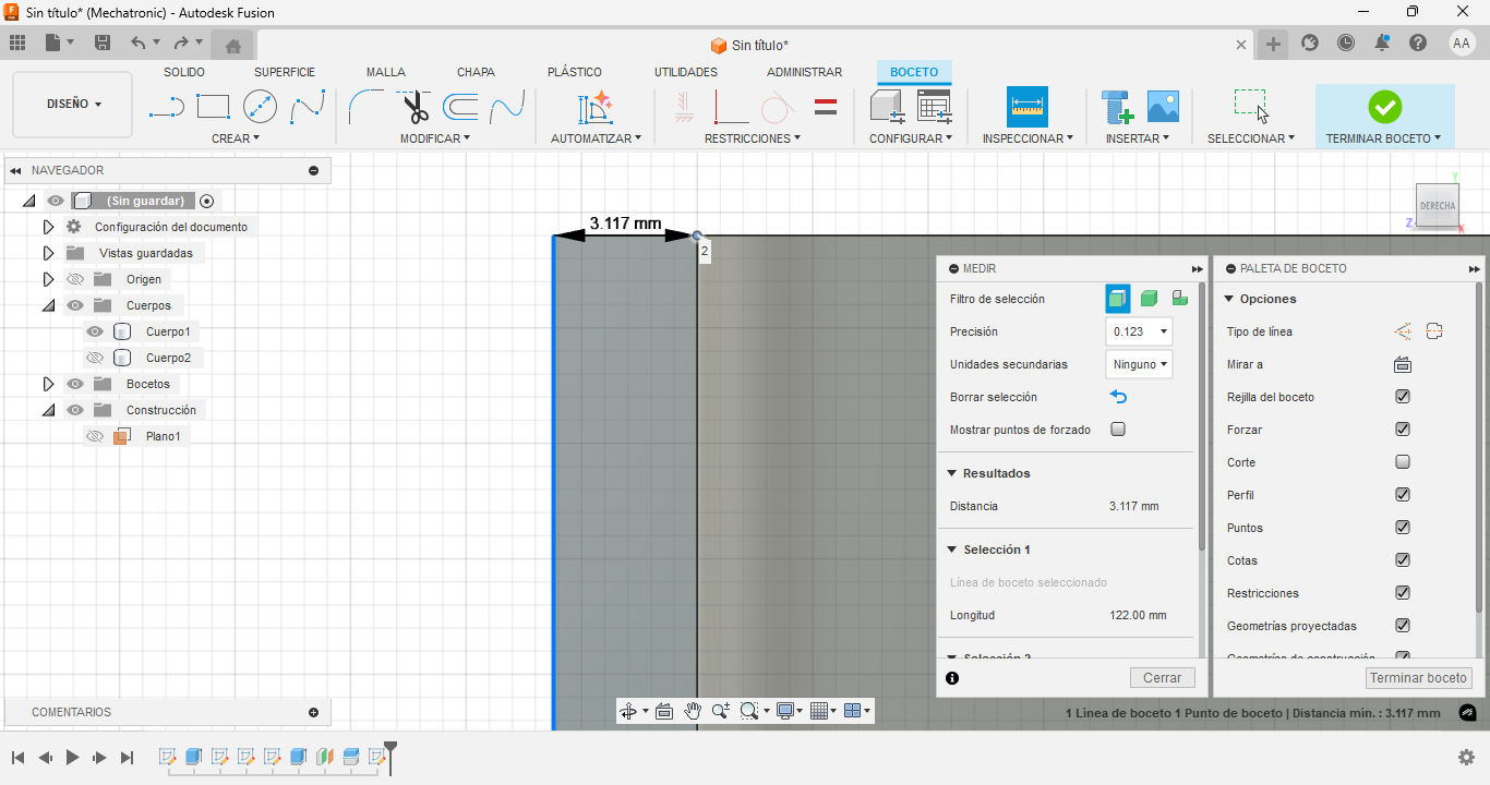
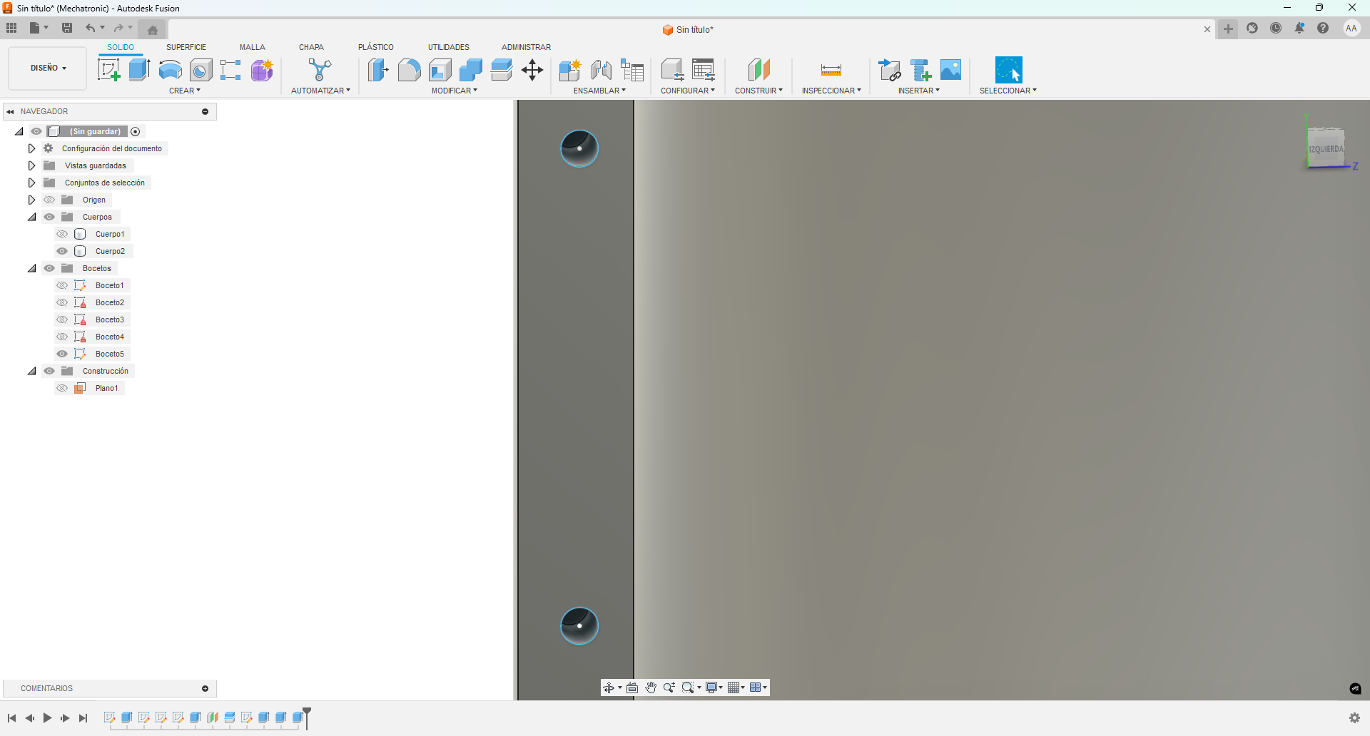
8. Zoomed View of Holes
Inspect the cut holes to ensure correct alignment and size.
9. Using Analysis Tools
Use Fusion 360's analysis tools to check section cuts, curvature, and interferences.
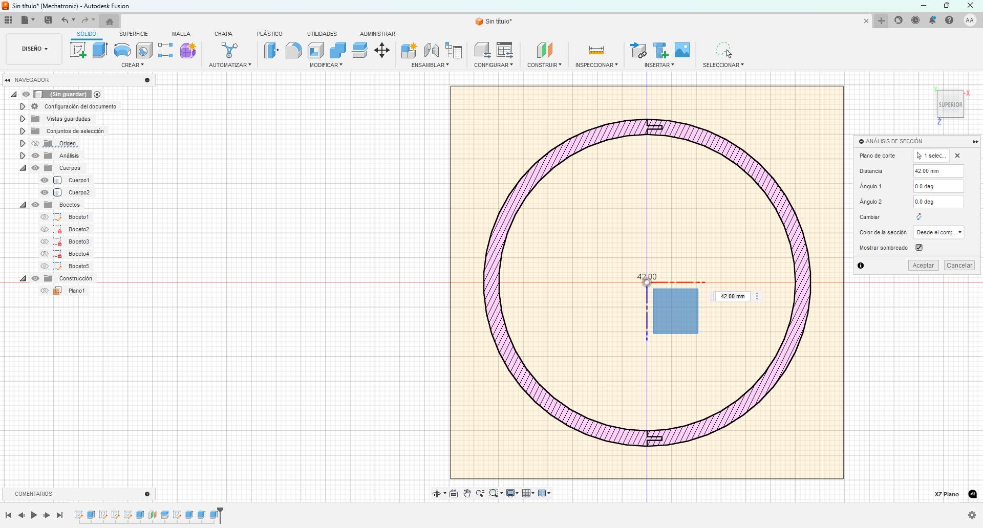
10. Creating Hexagonal Cutouts
Begin the design of hexagonal holes on the opposite side of the cylinder to allow interlocking elements or tightening.
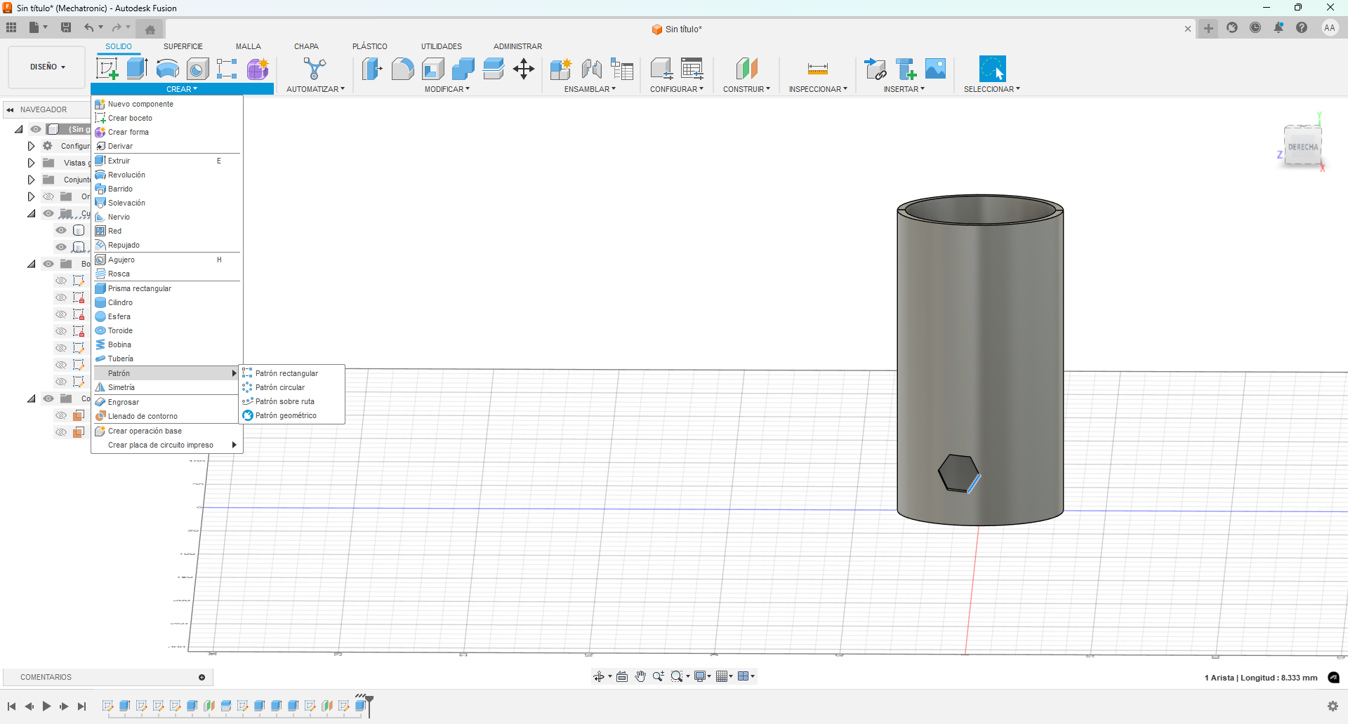
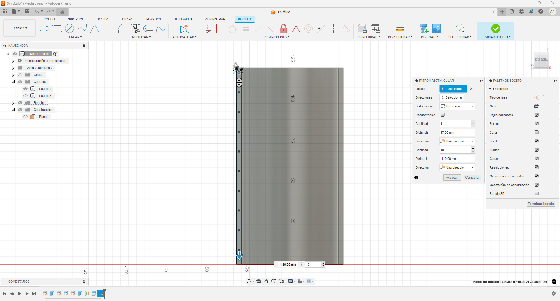
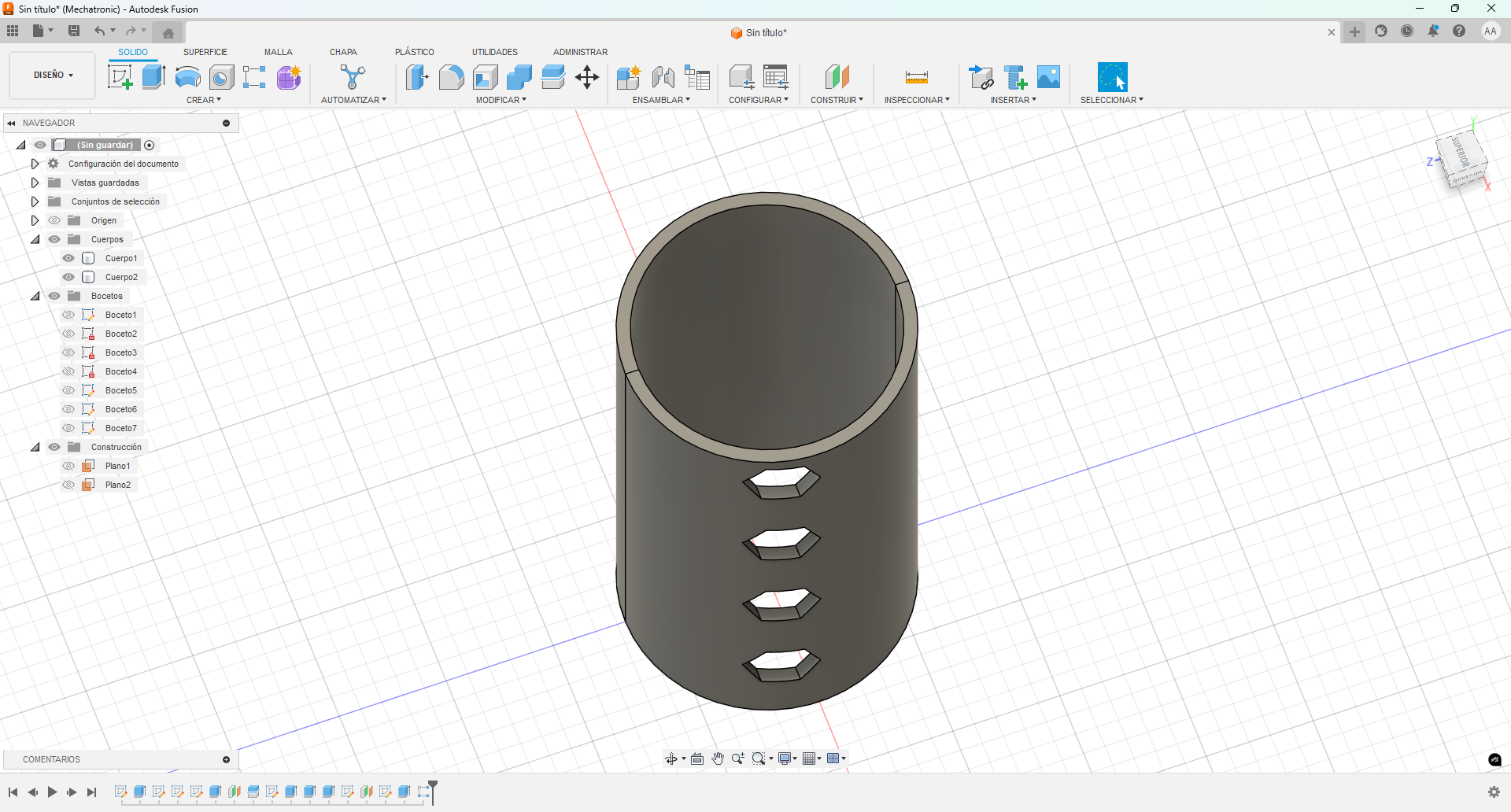
11. Patterning Hexagonal Cut
Use the rectangular pattern tool to duplicate the hex cut in a linear fashion along the body.
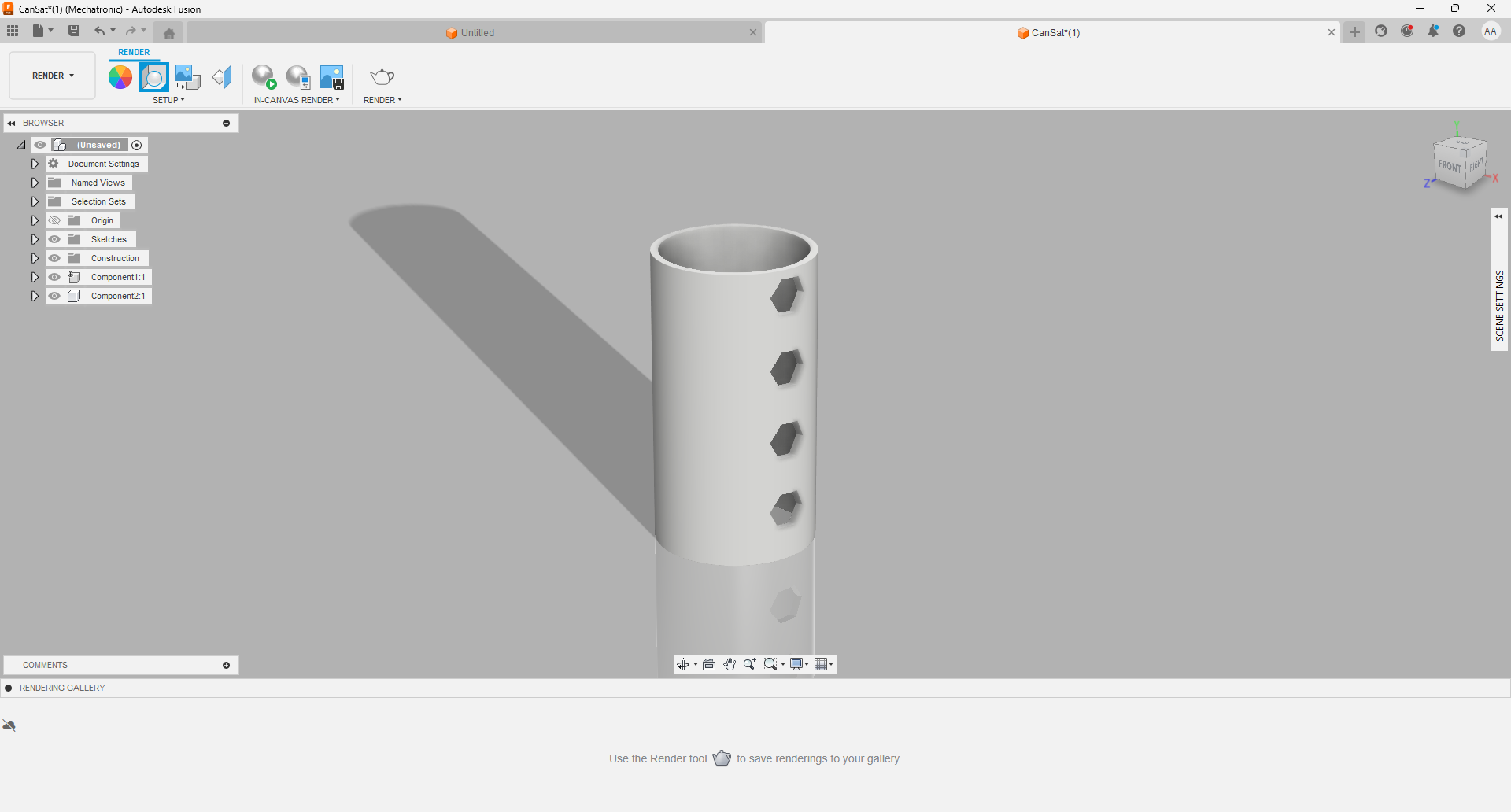
Animated Video
Finally, I rendered in the corresponding section of fusion 360, using a configuration of generating a mirror effect on the floor and a light from right to left on the figure.
Designing the CanSat using Tinkercad
To design the cylindrical structure for my prototype using Tinkercad, I followed the steps below:
Step 1: Accessing Tinkercad
Go to tinkercad.com and log in or create an account if needed. In my case I already had an account created and associated with autodesk since autocad is also from the same company.
Step 2: Opening the design dashboard
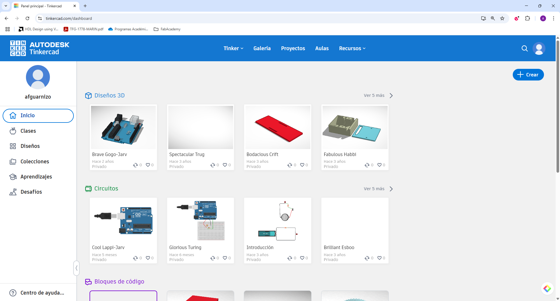
Once logged in, you can access to all 3D designs or start a new one. I had already built several previous designs related to arduino and with some boxes that served as support for the servomotors of some fixed wing drones.
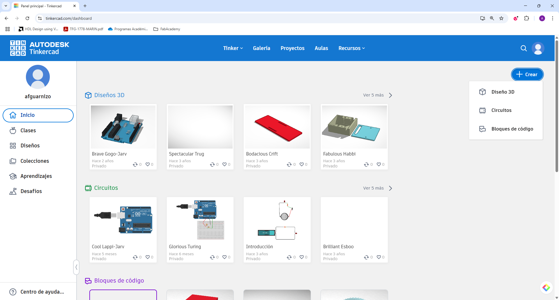
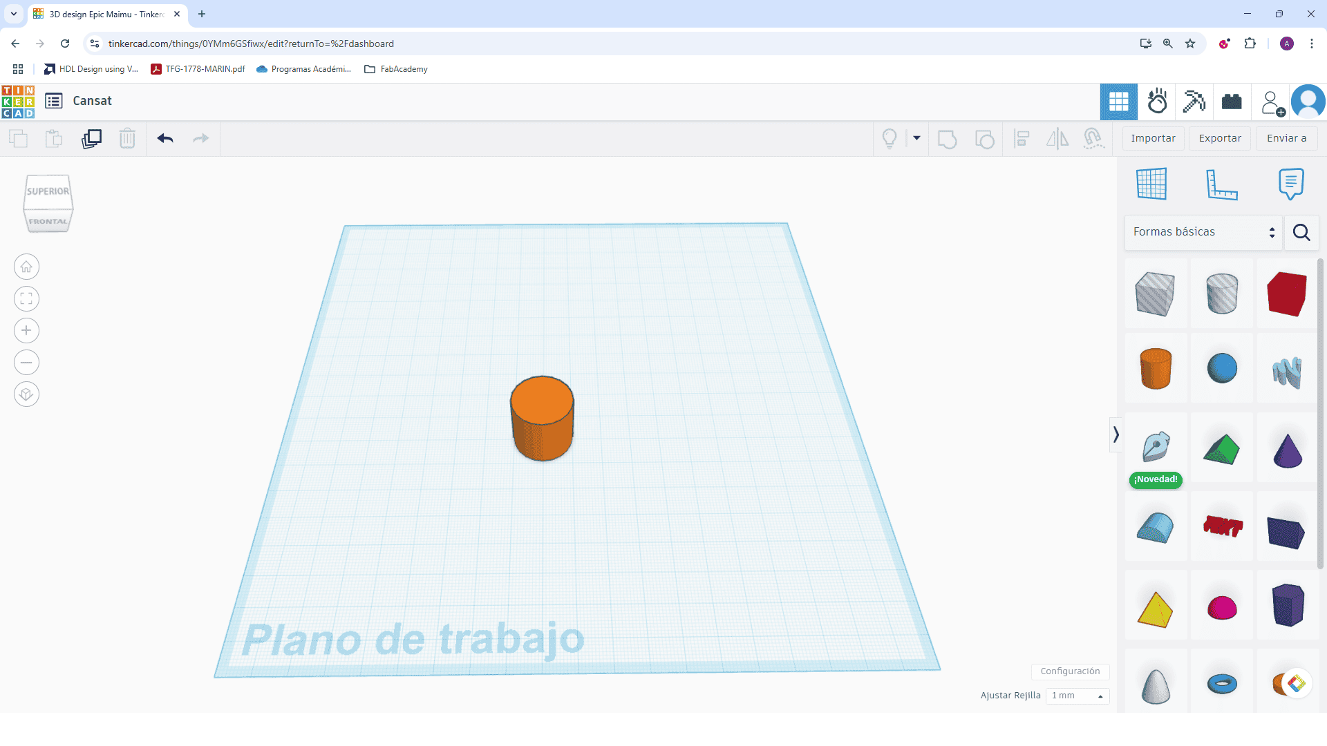
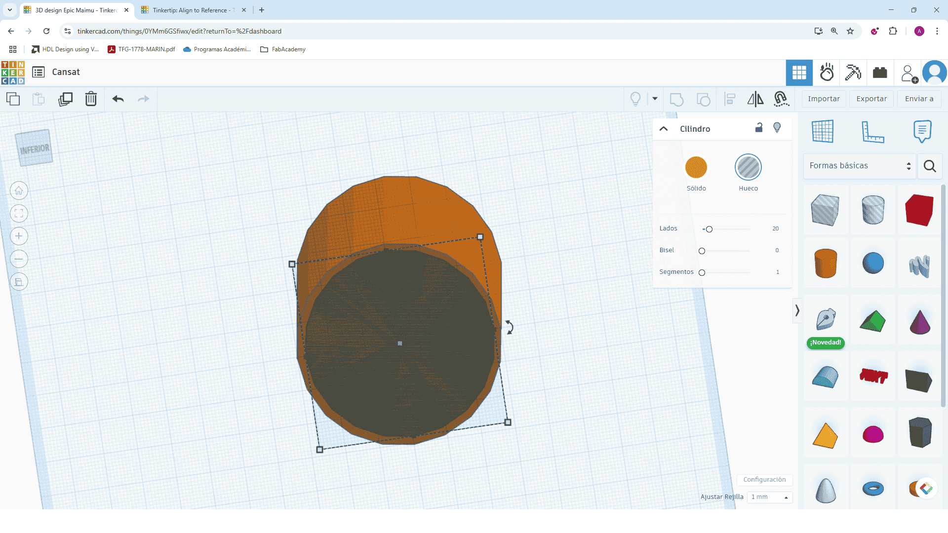
Step 3: Creating a cylinder
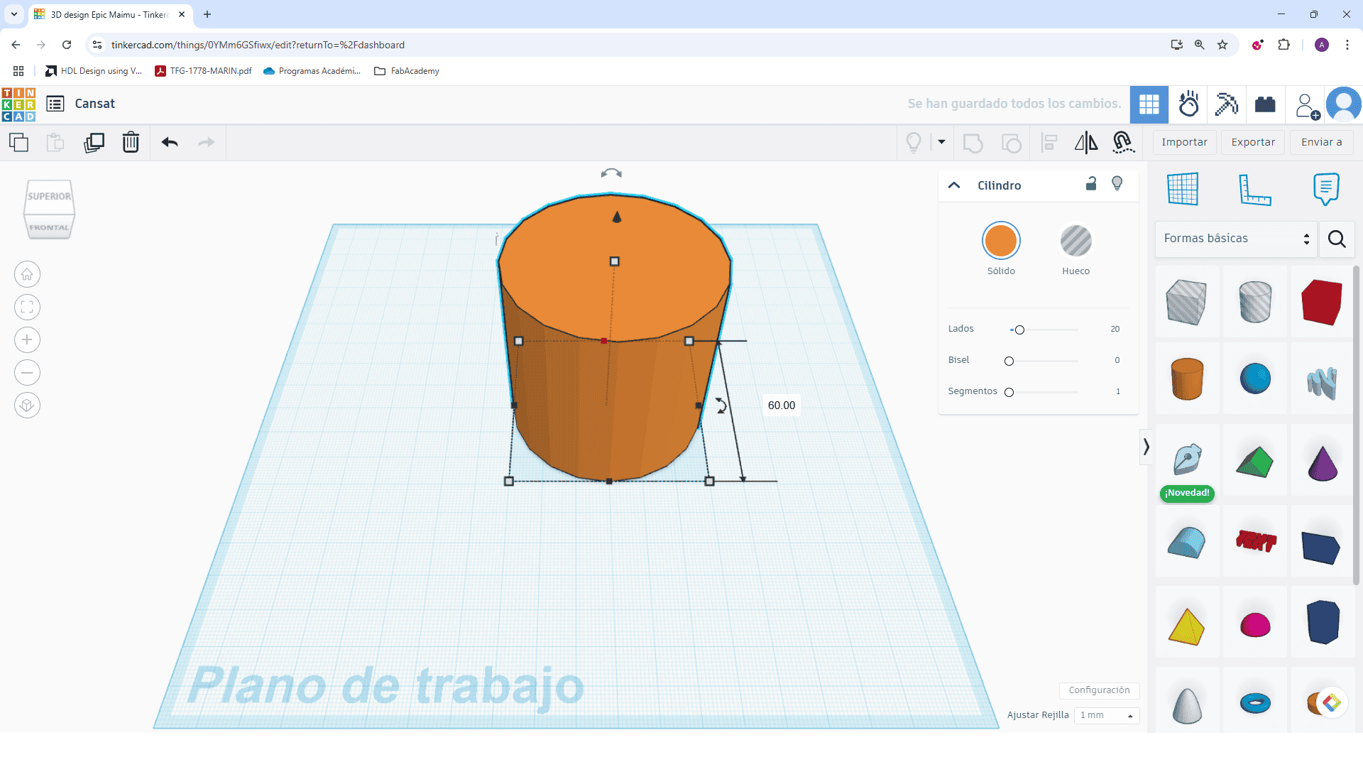
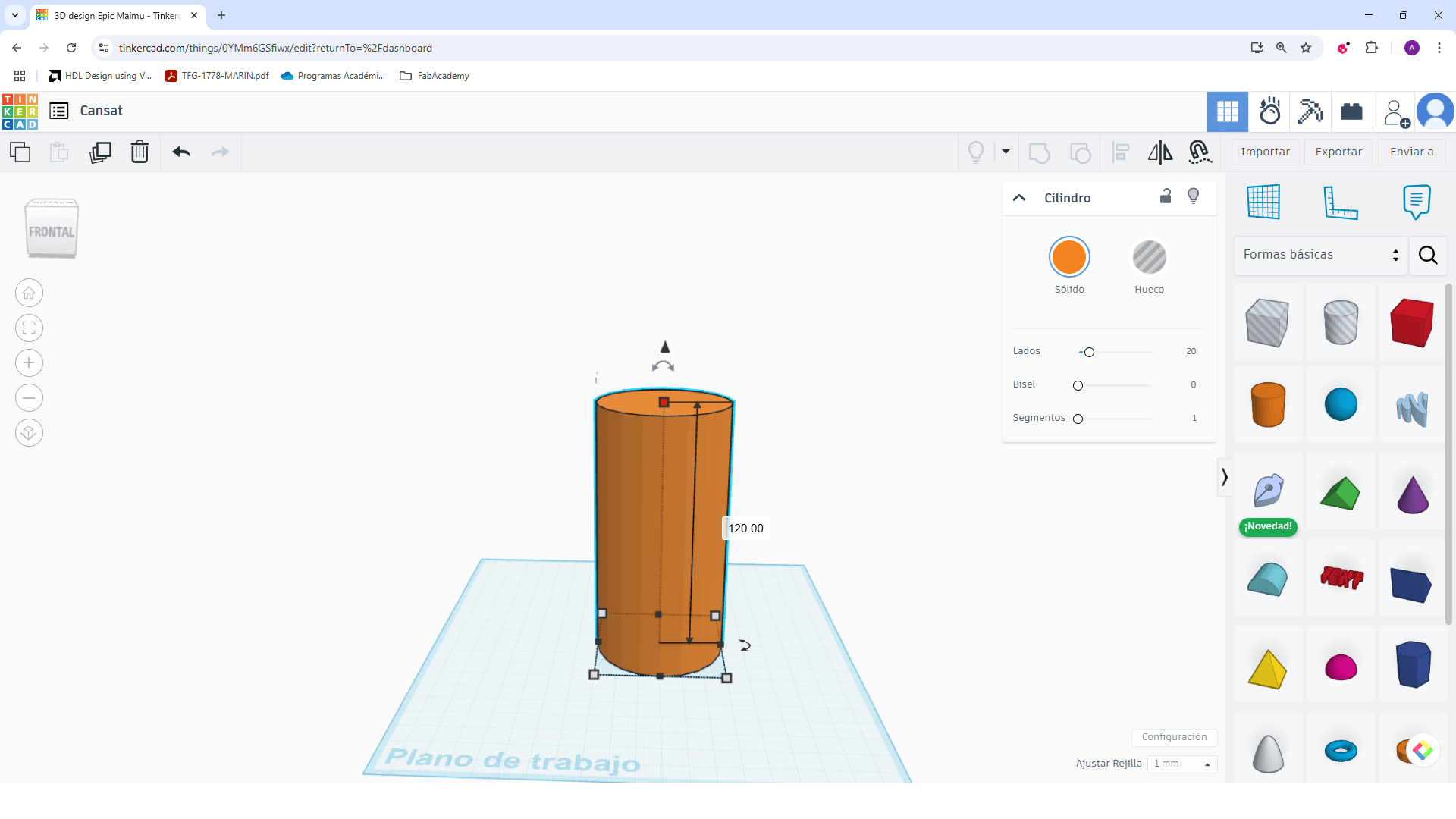
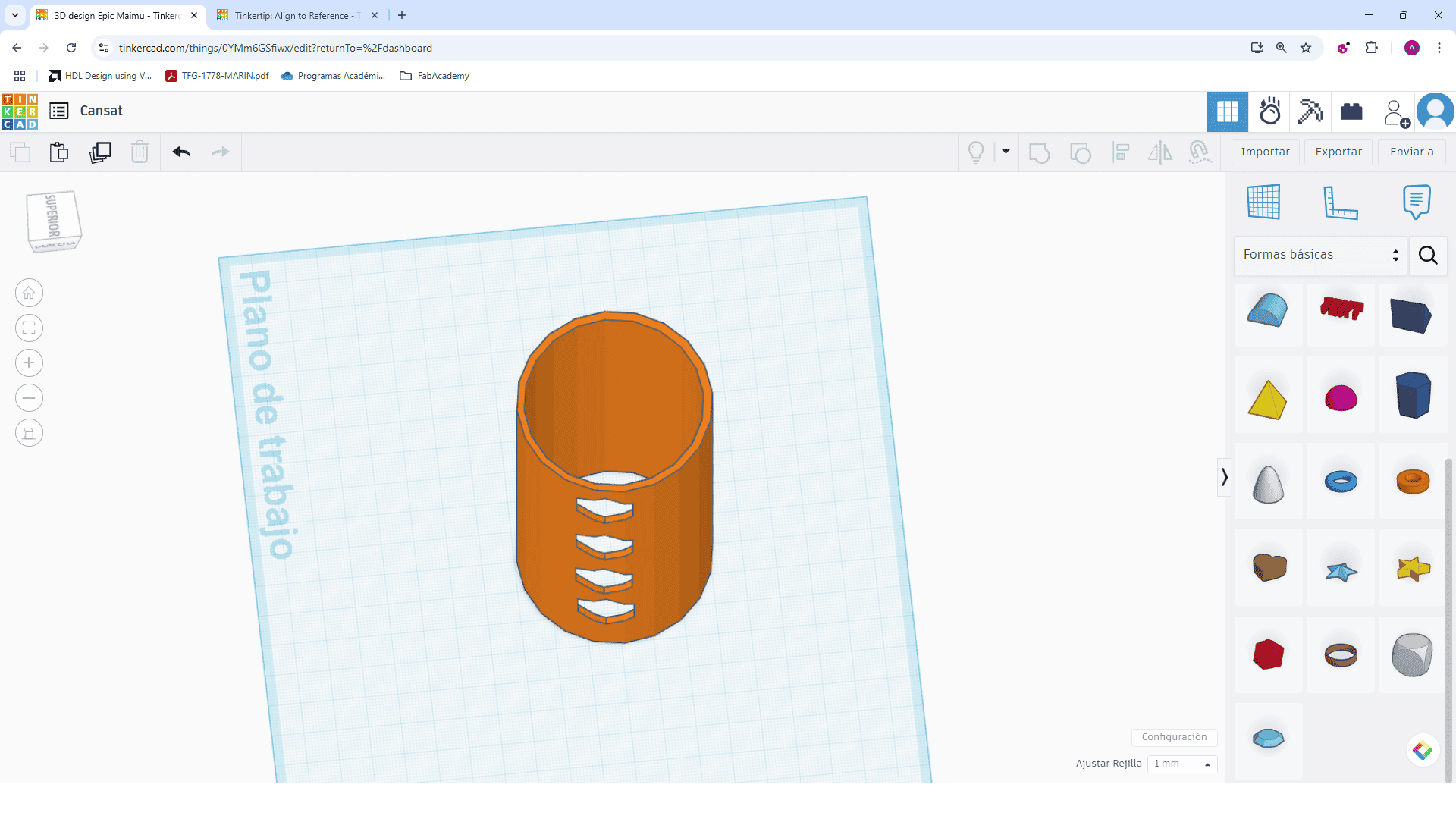
Drag a solid cylinder from the basic shapes menu onto the workplane and adjust the dimensions (diameter to 60 mm and height to 120 mm)
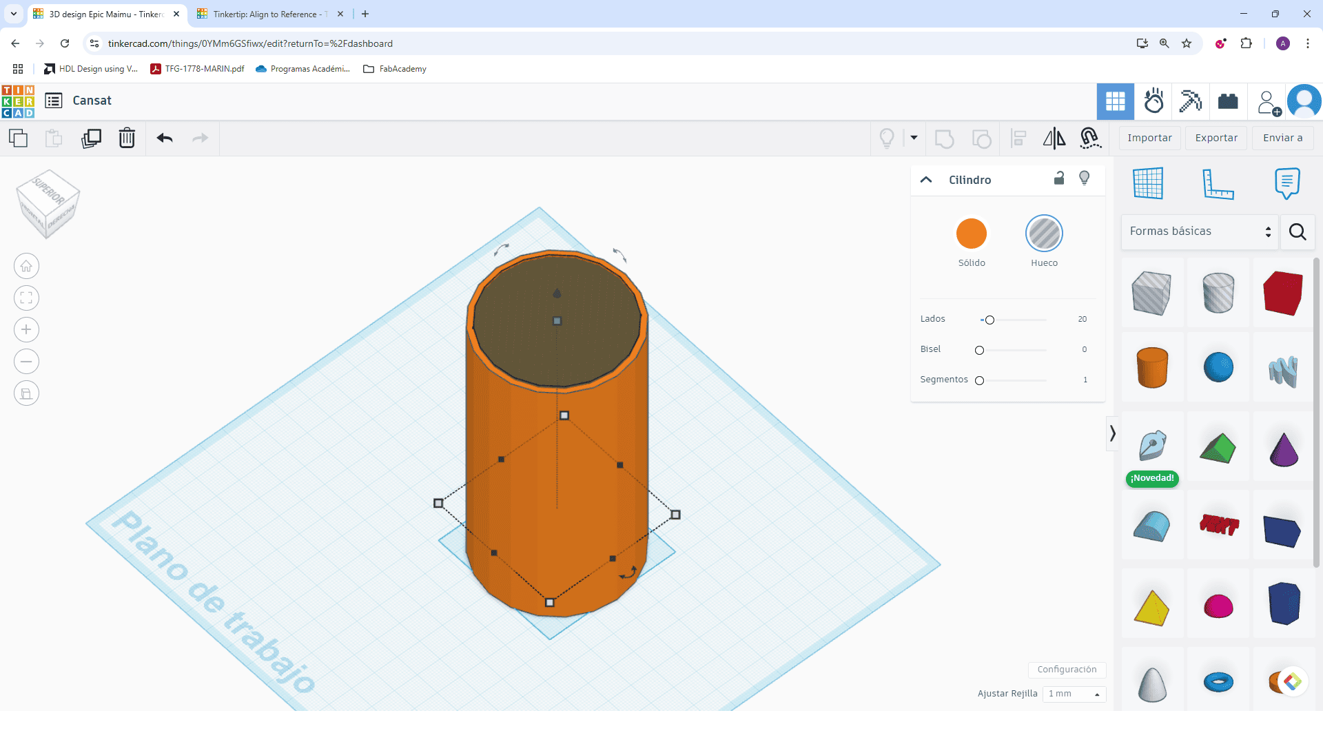
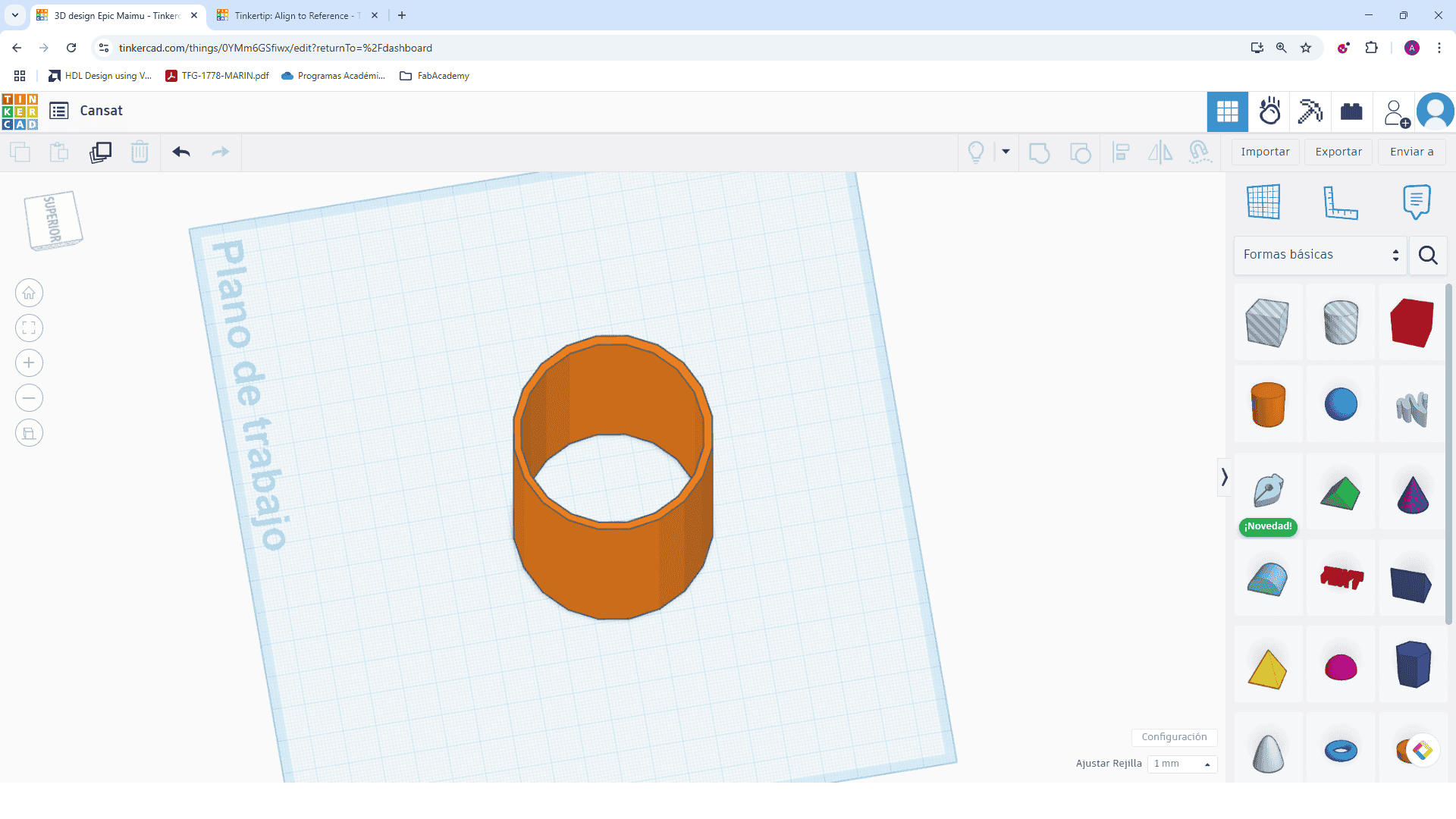
Step 4: Creating the inner hollow
Drag another cylinder, set it to "Hole", and align it concentrically with the solid one. Then group them to make the hollow.
Step 5: Insert hexagonal hole
From the shapes menu, drag a hexagon and set it as a hole. Position it near the cylinder wall.
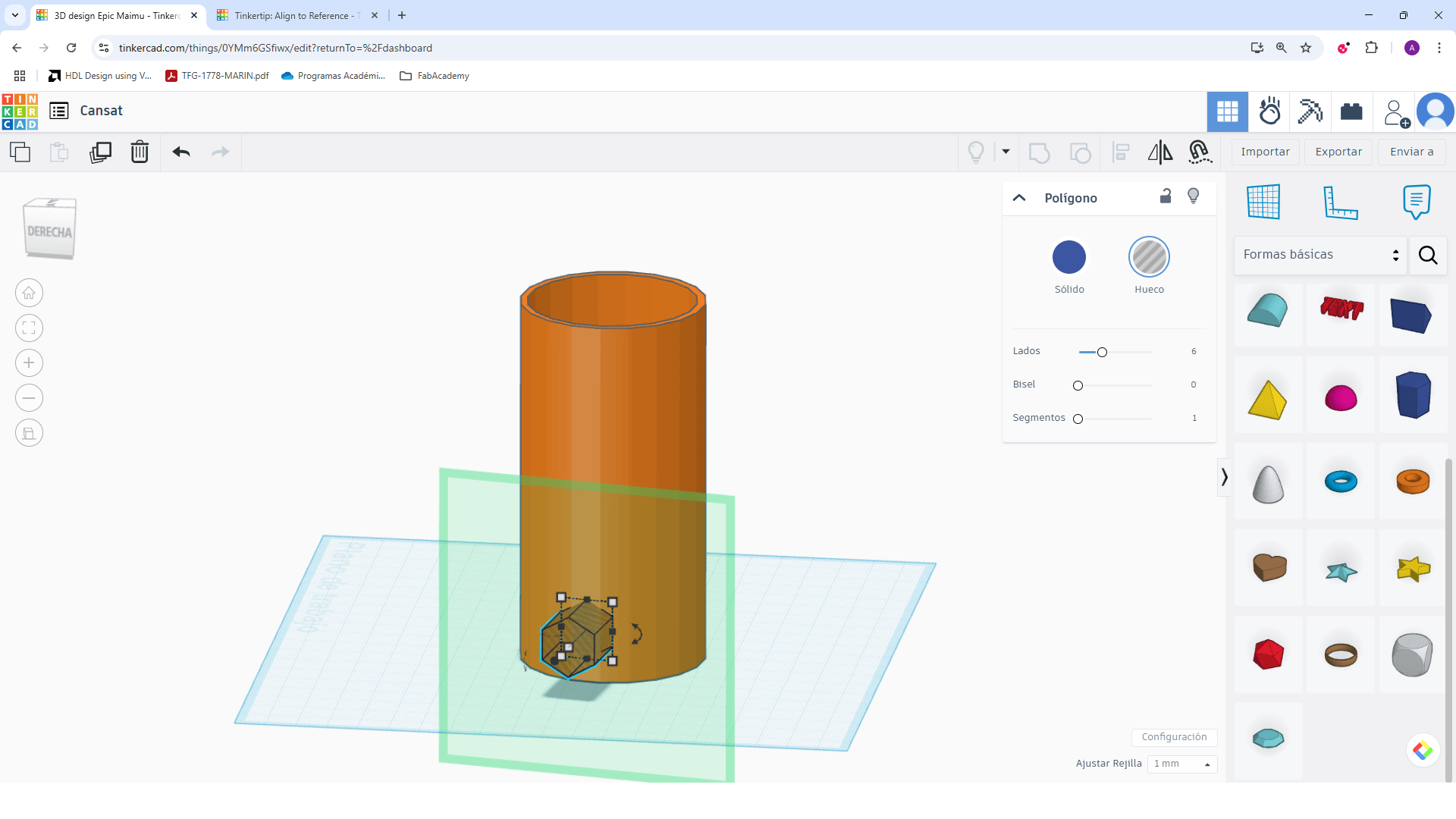
Step 6: Align the hexagon with the cylinder
Use the align tool to center the hexagon on one side of the cylinder.
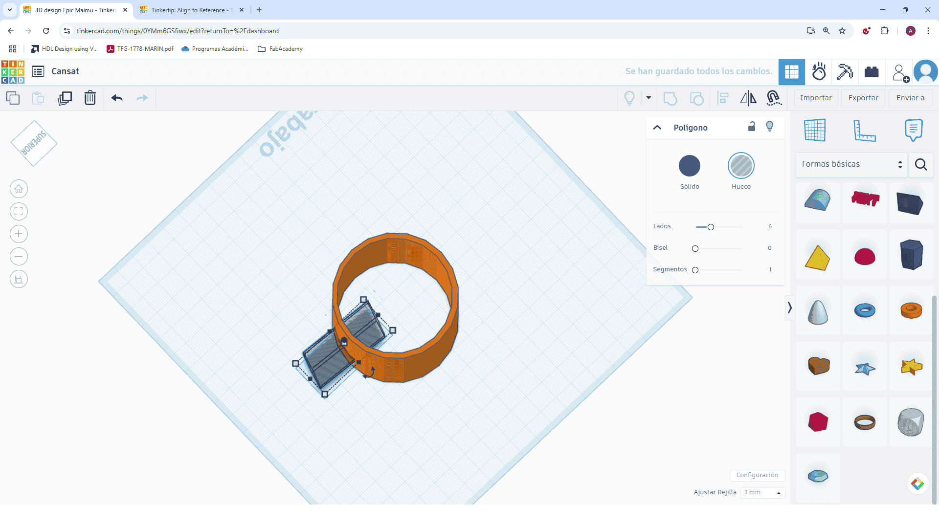
Step 7: Group to make the hole
Select both shapes and group them. This will subtract the hexagon from the cylinder.
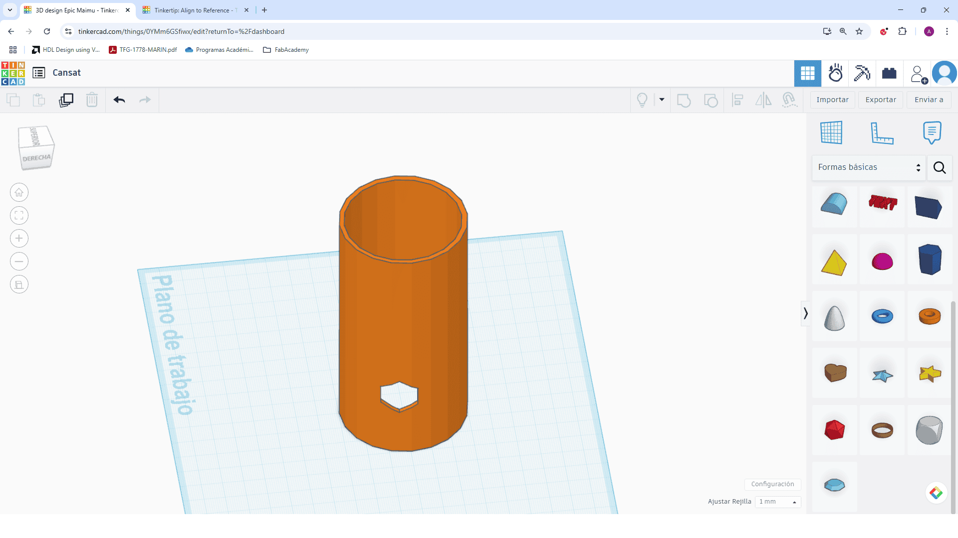
Step 8: Duplicate the hexagon hole
Duplicate and move the hexagon downward. Repeat this process to form a vertical array.
Demonstrating Image and Video Compression
1. Image Compression
To reduce the file size of an image, I used two tools:
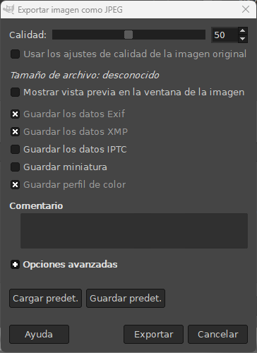
- GIMP: I opened a high-resolution image, exported it as JPG and adjusted the quality to 50%.
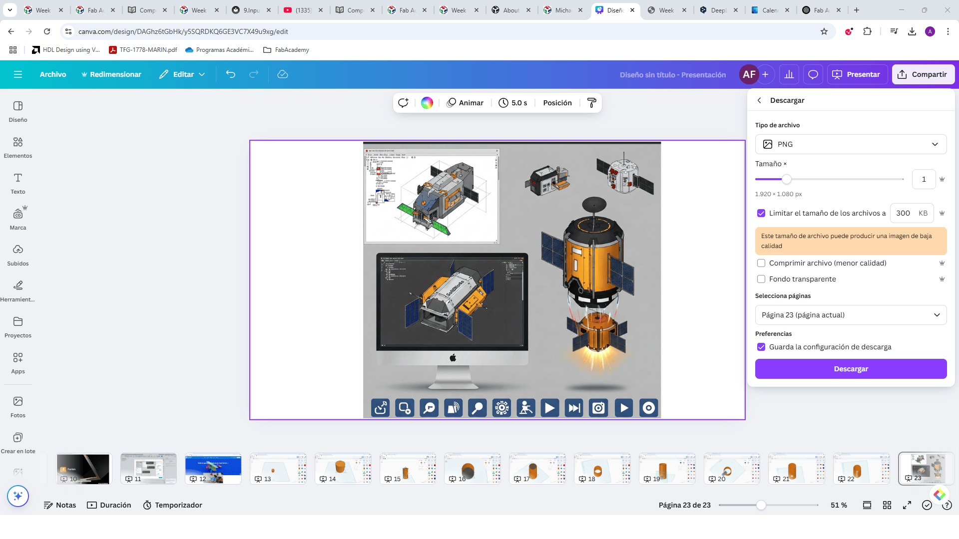
- Canva: I uploaded the original image, then exported it in PNG format at low resolution.
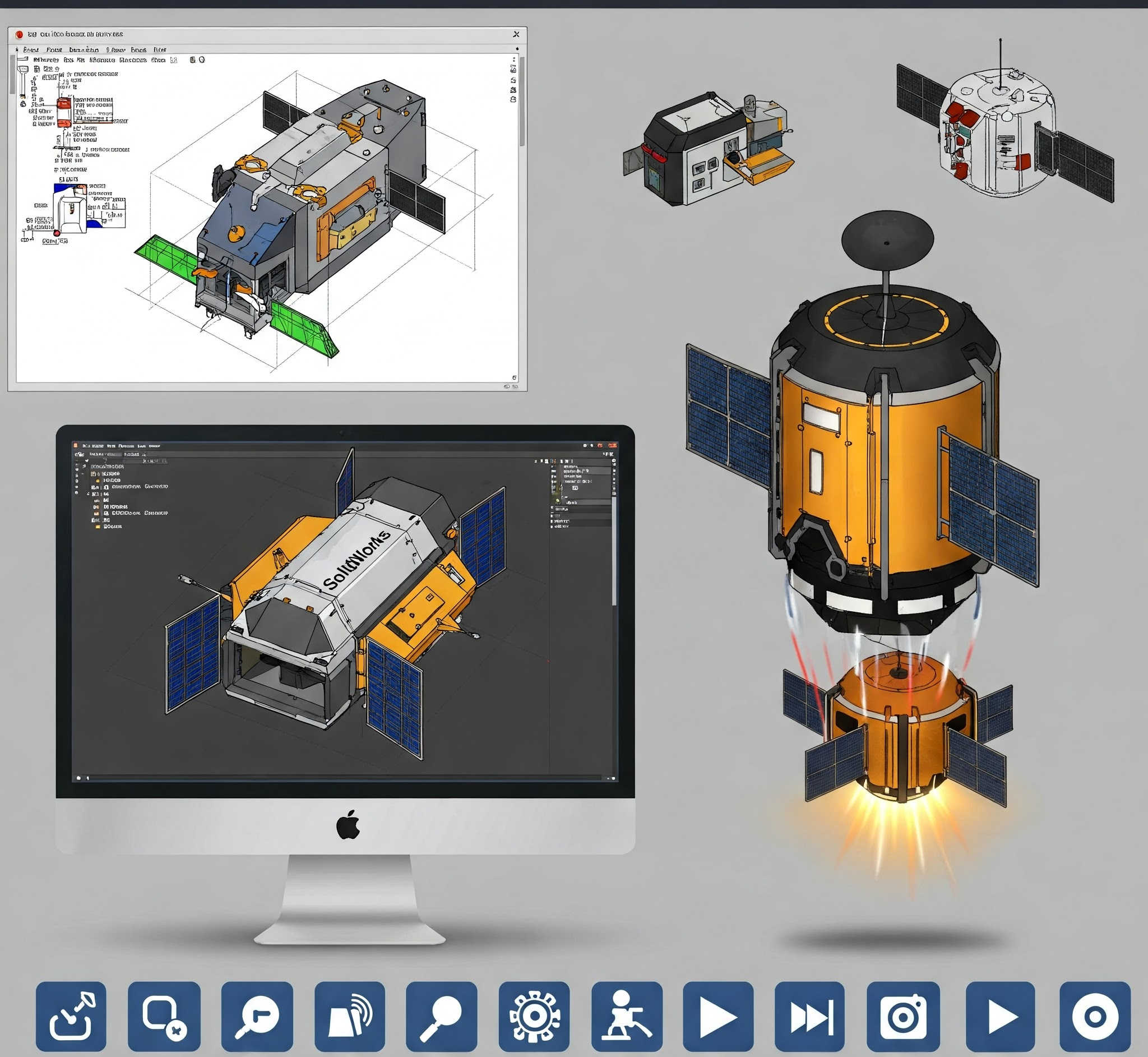
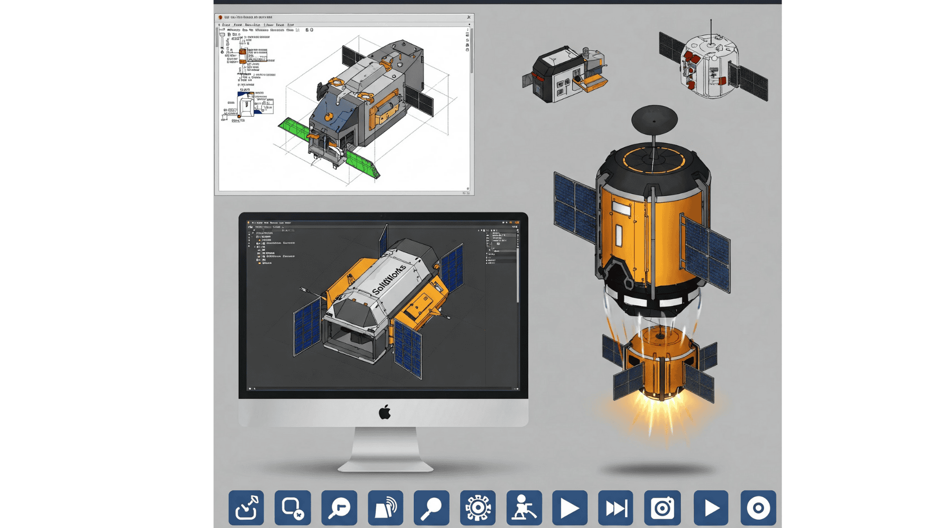
Below I compare the original image with the compressed versions:
Original Image (High resolution, Gemini generated image, size: 2.65 MB)
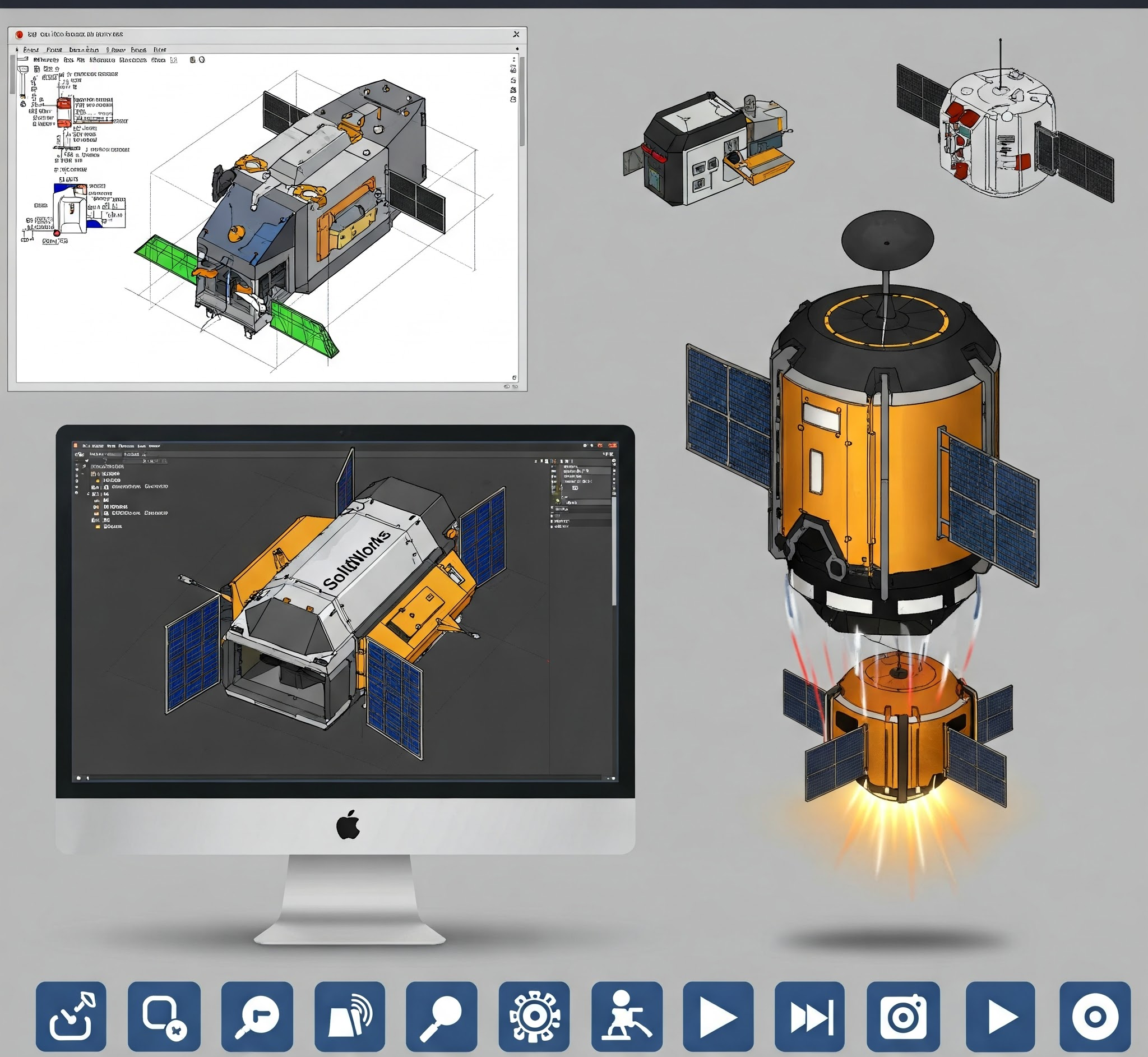
Compressed with GIMP (JPG, quality 50%, size: 278 KB)
Compressed with Canva (PNG, reduced resolution size: 299 KB)
PNG is better for preserving details and transparency. However, JPG is more efficient for web usage when file size matters. Depending on the goal, both methods can be effective.
Video Compression Using CapCut
To demonstrate video compression, I used CapCut, a free and easy-to-use video editor. Here are the basic steps I followed to export a compressed video in MP4 format:
- Open CapCut and create a new project.
- Import your video by clicking the "+" button and selecting the file you want to compress.
- Trim or edit your video if needed (I cut the video from 22 seconds to 5 seconds).
- Click on the "Export" button located in the upper-right corner of the screen.
- In the export settings, make sure the Format is set to
MP4. - Adjust the Resolution (e.g., 720p) and Bitrate (e.g., Medium or Low) to reduce file size.
- Click "Export" again to compress and save the final video.
This method reduced my video size significantly while maintaining acceptable visual quality.
Edited video MP4
Original video: technology
Comparative Table of Software Tools Used
| Software | Type | Strengths | Selected | Reason |
|---|---|---|---|---|
| Inkscape | 2D Design | Open source, precise vector editing, SVG support, compatible with xTool | Yes | It enabled clean vector paths and integration with xTool for accurate laser cutting. |
| xTool Creative Space | 2D Laser Software | Intuitive interface for laser cutting and engraving, supports SVG and DXF, quick preview | No | Useful for execution, but depends on pre-made vectors from other tools like Inkscape. |
| Tinkercad | 3D Design | Beginner-friendly, browser-based, easy to manipulate basic shapes | No | Good for initial prototypes, but lacks precision and depth for advanced designs. |
| Fusion 360 | 3D Design | Parametric modeling, simulation, assemblies, CAM tools, collaborative environment | Yes | Best suited for detailed, functional, and professional modeling needs. |
| GIMP | Image Compression | High control over compression quality, open source, supports layers and batch editing | Yes | Excellent for image manipulation, transparency control, and exporting in custom formats. |
| Canva | Image Compression | Fast and simple, online platform, allows export with resolution settings | Yes | Useful when working quickly online, with good balance between size and quality. |

