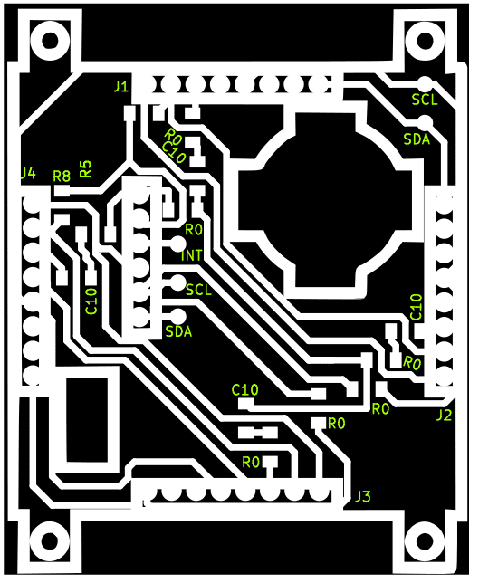
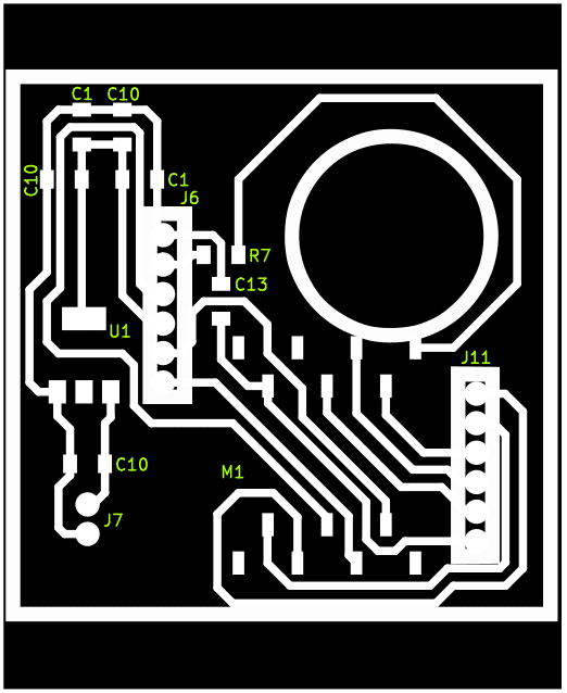
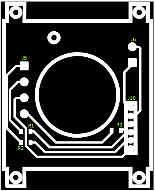
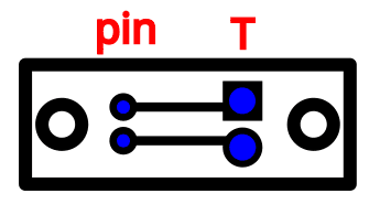
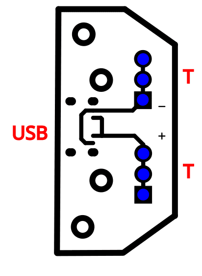
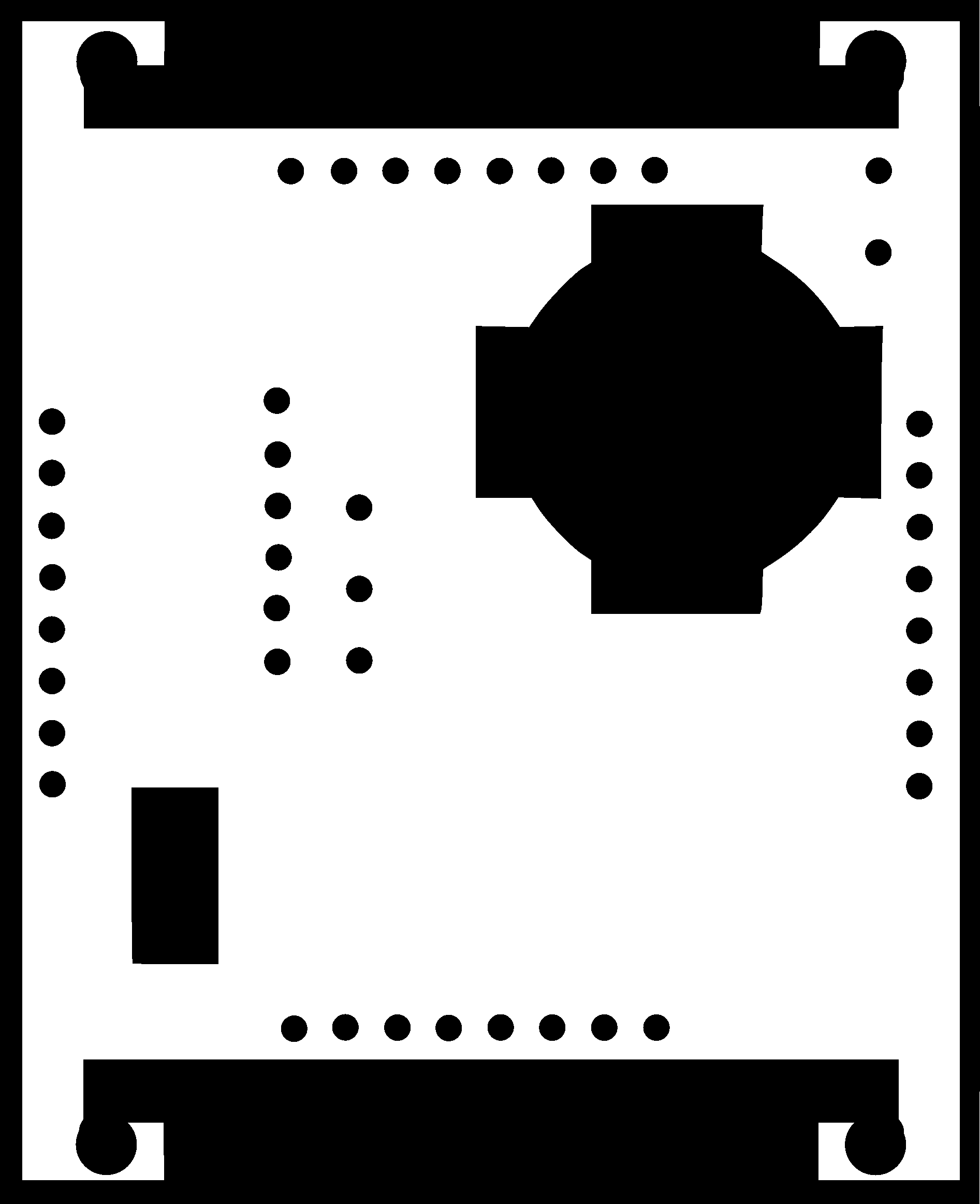
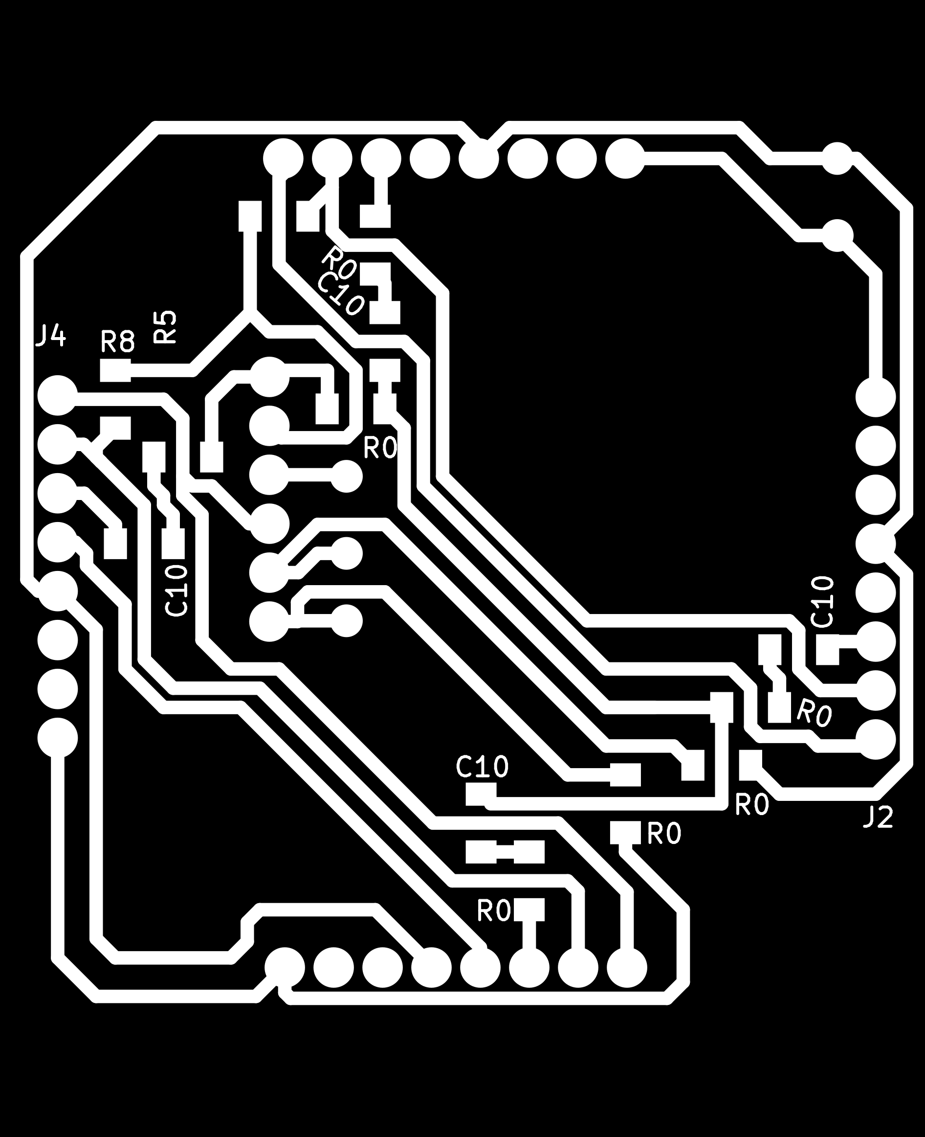
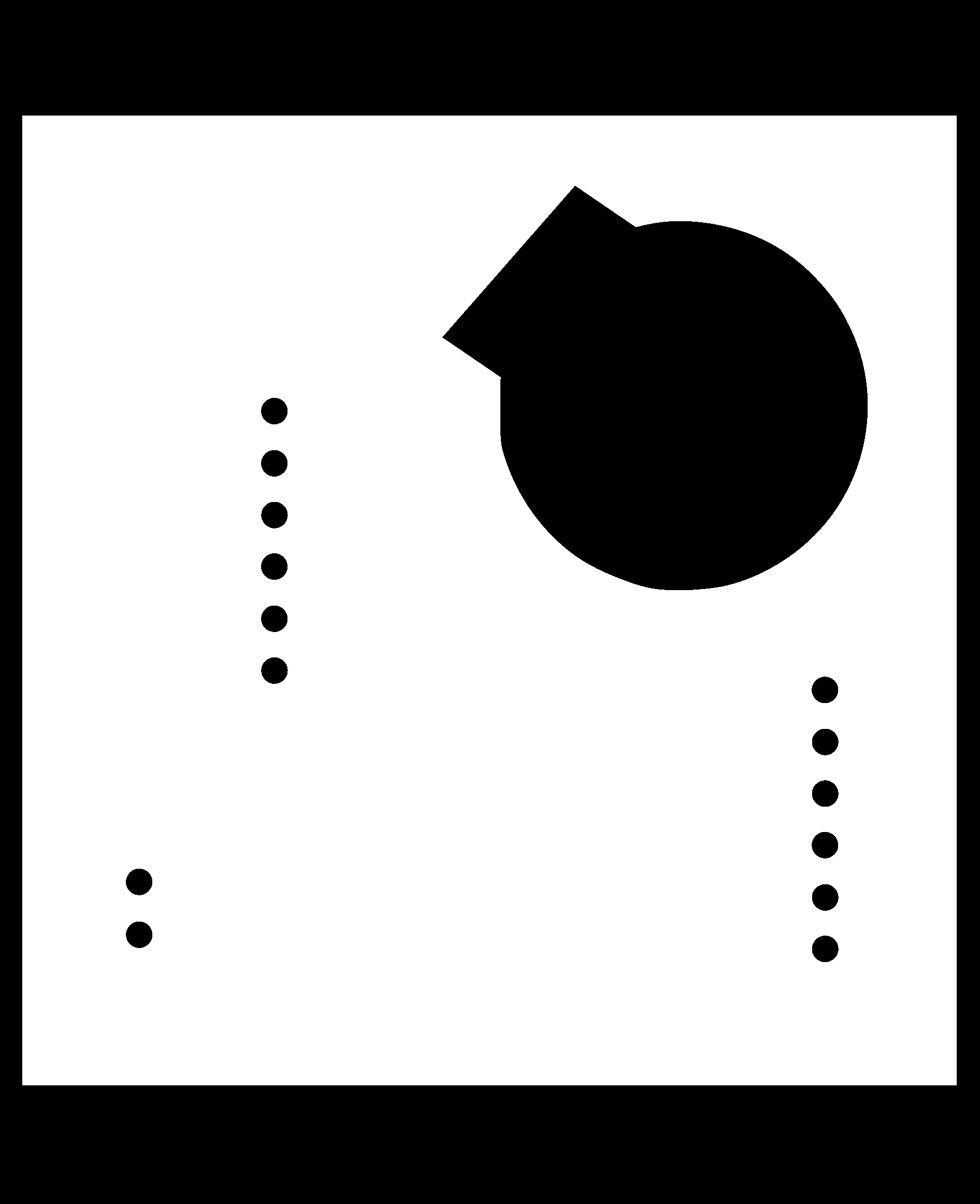
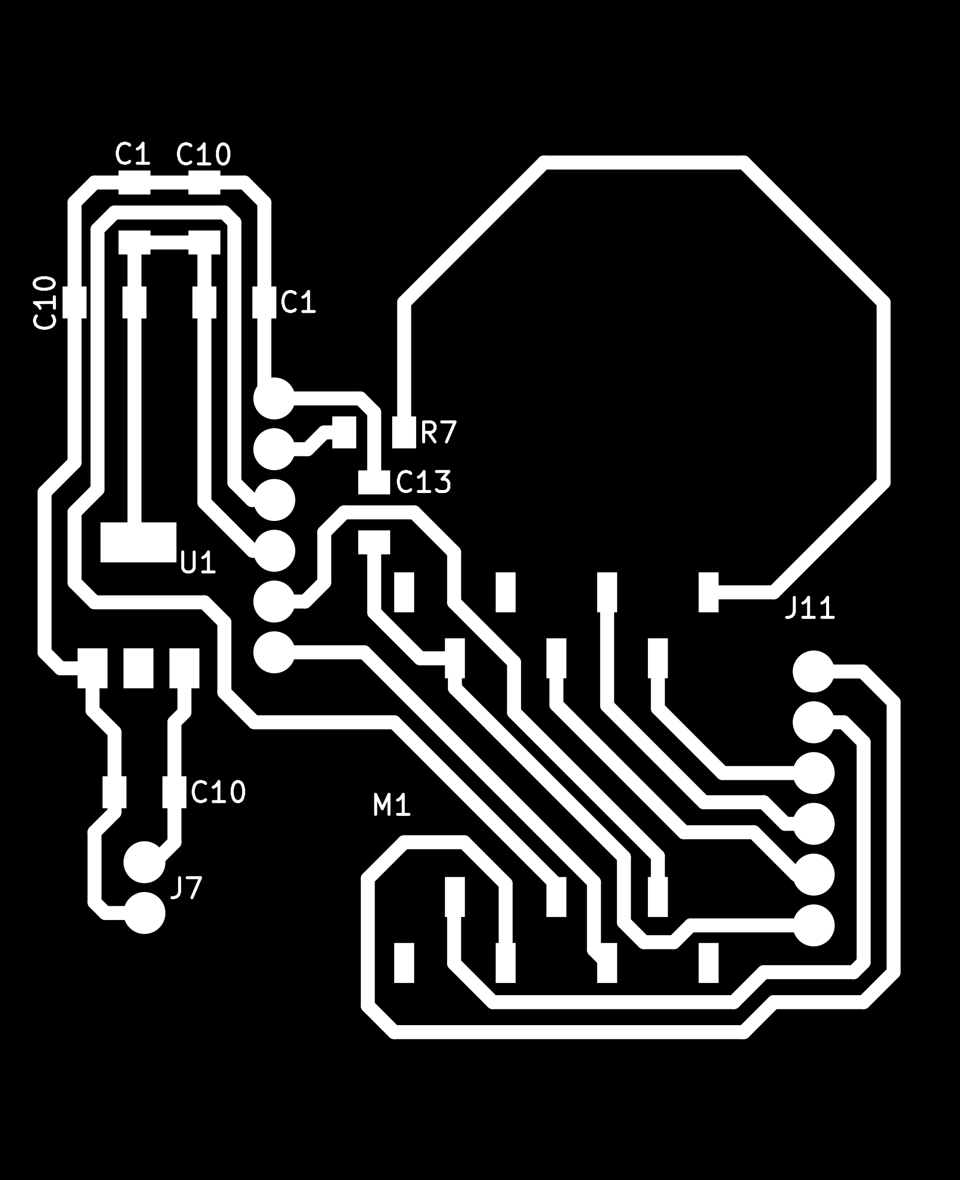
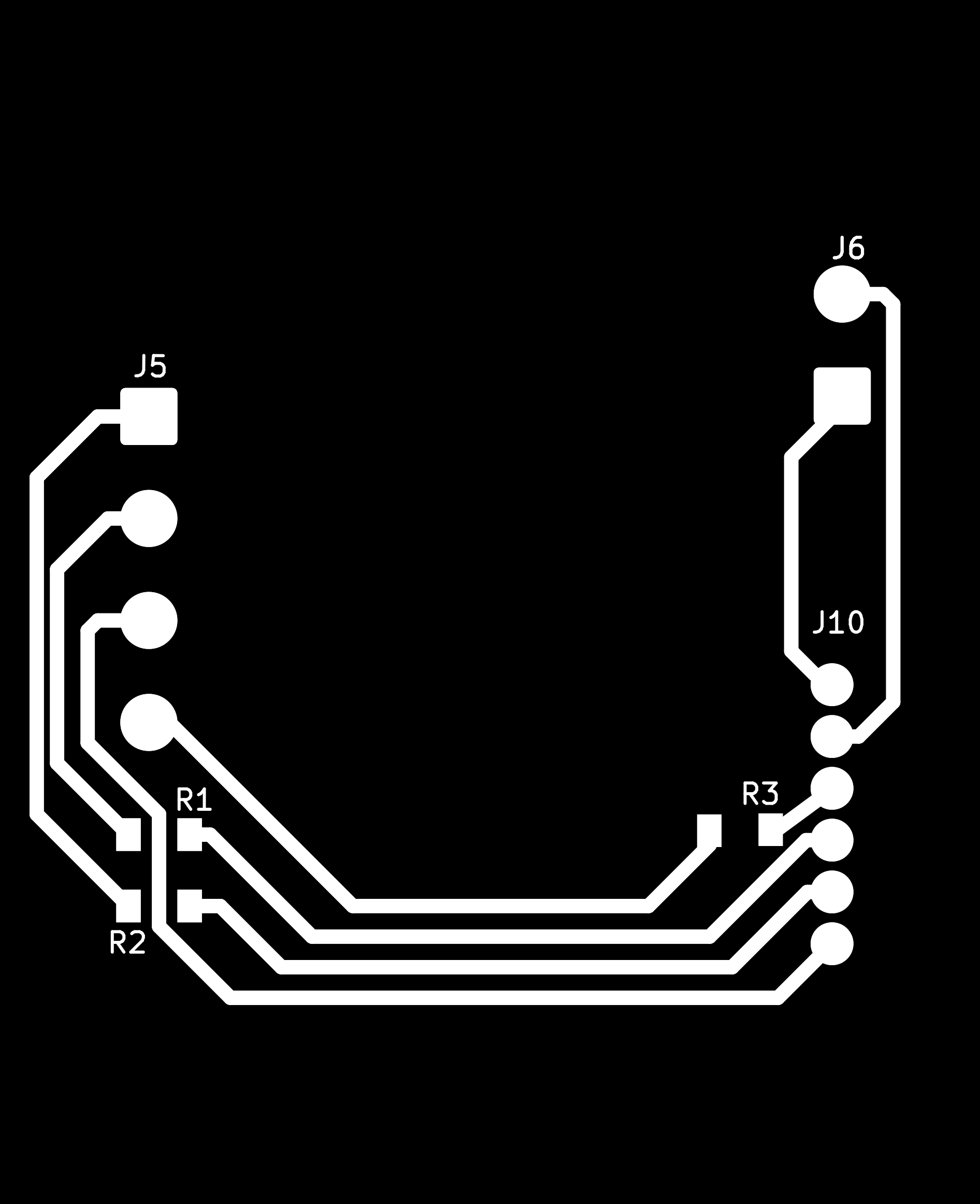
Solder the PCBs. Here is a picture on where each component is supposed to go:
Left to right: Top Layer, Middle Layer, Bottom Layer
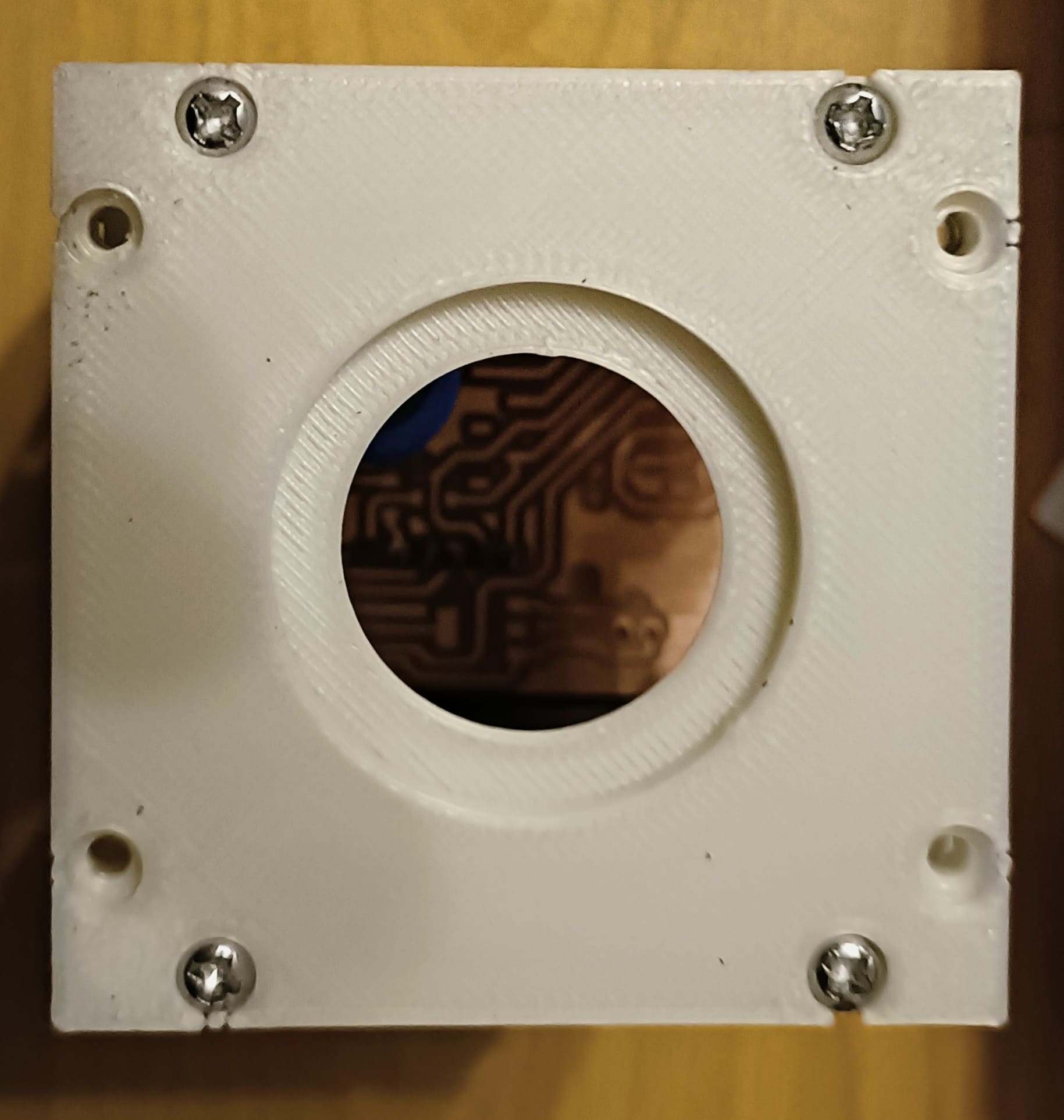
Align the two halfs by turning one of them upside down. Connect them by screwing on the bottom plate.
Only do the 4 screws shown in the picture below. Before you do that, put the nuts into their respective holes. Use the 8mm long screws.
Screw in the 4 screws in this manner.
Do the same thing with the top piece of the robot.
Insert all the nuts into their respective holes behind the screws that are facing to the center of the cube.
Repeat the same with the holes facing to the center of the cube on the other side of the halfs.
Insert the nuts and insert the screws with the 20mm length in the final 4 holes in the bottom piece. Only screw it in until the tip of the screw starts showing.
Attach a vibration dimming spacers to the tip of those screws. Screw in the screws deeper until the tip is visible under the anti vibration spacers.
Insert the bottom Layer underneath the lower RFID module holders. Make sure the battery and charger holes are aligned. Gently push it on the screws.
Screw the screws in so that the tip is visible.
Insert another anti vibration spacer onto the screws. Complexly tighten the screws from underneath the bottom piece.
Place the rfid modules from the top into the sides to place them in a way to connect the pins into the bottom layer from the bottom. Solder the male pins to the rfid module.
Insert the middle layer through the top and connect it to the bottom layer using the pin headers.
Insert the screw into the hole in the top layer.
Repeat the same mounting strategy for the top piece and top layer. The screws to mount the top piece should be on the same sides as the ones from the bottom piece.
Attach the charging module holder to the screw from the top layer by turning the nut within the mount.
Insert the pieces of the button without the switch through the top layer and top piece.
Mount the battery into the battery lid by putting it between the battery lid's spikes and isolate the cables.
Build the rest of the button as shown below and put it in place into the upper part of the button.
Instruction to build up the lower part of the button
Insert the battery lid with the battery into the bottom piece, bottom layer, and middle layer.
Attach the side plates to the sides of the cube with each of the same facing each other.
Assembly instruction for a charging box for 6 puzzling robots
.jpg)