Computer controlled cutting
Tasks
- Group assignment:
- ✔ Test the design rules for your 3D printer(s)
- Individual assignment:
- In Process: Design and 3D print an object (small, few cm3, limited by printer time) that could not be made substantively
- X 3D scan an object (and optionally print it)
Design sth subtractable
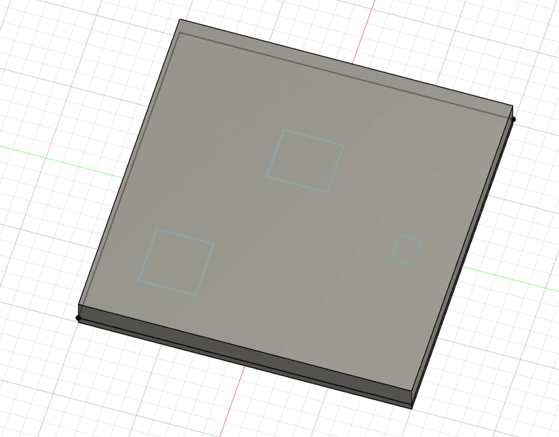
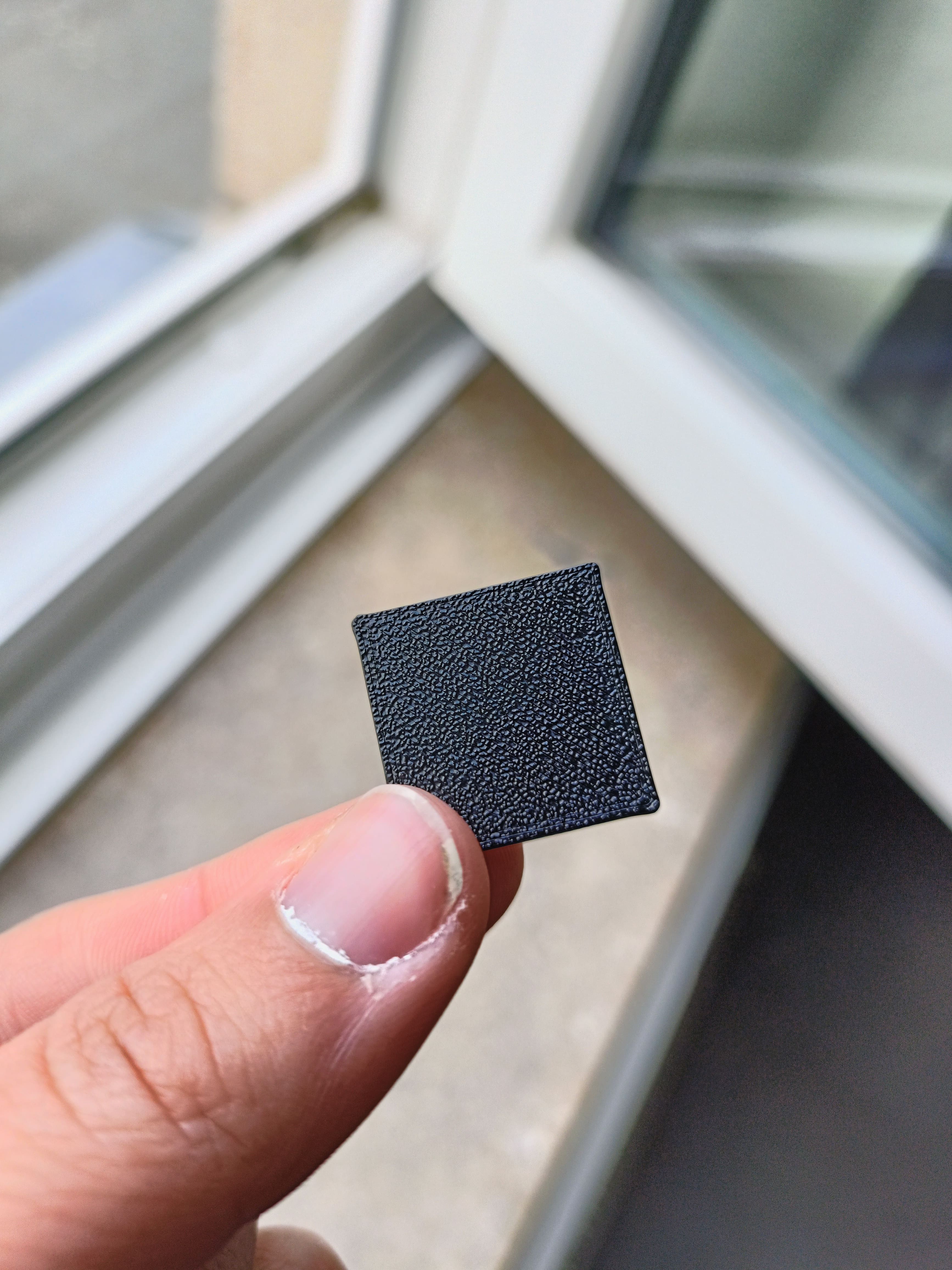
This piece is not subtractable bc it is impossible to get these holes into the cube at the same location every time. It is also not possible to keep them there fixed because there is no connection to the outside.
You'll find the download files in the cloud to keep this page in minimal size.
3D design puzzRob pieces
For more information and pictures please visit the final project page.
Download link files:
- Download: Half a puzzlingRobot assembled FCStd
- Download: Modular cornerInner design V4 FCStd
- Download: Modular cornerOuter design V4 STL
- Download: Modular cornerInner design V4 STEP
- Download: Modular cornerOuter design V4 STEP
- Download: all corner pieces GCODE prusa MK4
These could also be made substantively but are necessary for the final project.
Design ideas:
- Easy electronics mounting by adding pieces step-by-step
- Designed around the RFID module
- Make them as small as possible from above to fit more of them on a table/ floor
- If changes in size are required, only half a set of corners has to be printed. Thus, saving recourses and time as well as reducing the environmental impact.
Product description:
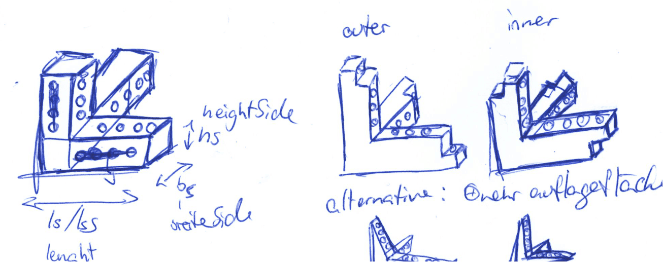
- There are 2 types of corners: Inner (longer side towards the middle) and Outer (longer side away from the robot).
- Each corner consists of 3 linearly independent fingers.
- One finger is longer. It is meant as the height and goes parallel to the longer side of the RFID module.
Assembly of robot:
- Print 4 corners of each type (Inner and Outer). Get the other required components.
- Start screwing the lower half of the robot. An Inner goes next to an Outer and so on.
- Program,attach, and electronics to the base. More detailed information tba.
- Finish attaching the upper half of the puzzRob including the button. Above each Outer goes another Outer. Same for the Inner.
- Charge if necessary.
- All set, enjoy :)
Group Assignment
Link to group assignment in lab
Theory:
- To print sth. the 3D-file needs to be in either a .stl or .step format
- Infills: Measure (in %) of how much filament is used inside the print. There are different structures, for example: honeycombs (very stable), cubic (fast-print, stressful).
- Placement and orientation determines the angles that can support higher or lower stress. Turn accordingly.
- Brin: Extend first layer. Adds stability. Use when adhesion problems or slim first layer.
- Draft: Brim but all over the shadow ground area of object.
- Layer height: height that the tip of the printer nozzle goes up after finishing on each layer. High layer height makes it faster but the result is less fine. 0.2mm is standard.
- Standard filament: PLA, PETG, TPU (if it has to bend, requires special settings).
- Once the slicing is completed, a gcode will be created. Copy it onto a USB, insert in printer, make sure the right filament is inserted, go!
- The print might stick to heat bed. usually heat bed is attached magnetically. Therefore, it can be removed, bent carefully and the piece should snap off.
Test results:
Using 0.4mm nozzle, 0.2mm layer height, structural preset, Official Prusa recommended programs otherwise.
Files:
- Link to Thingyverse: general testing plate
- Download: Clearance test STL
- Download: Overhang test STL
- Download: Min. width test STL
Hero Shots:
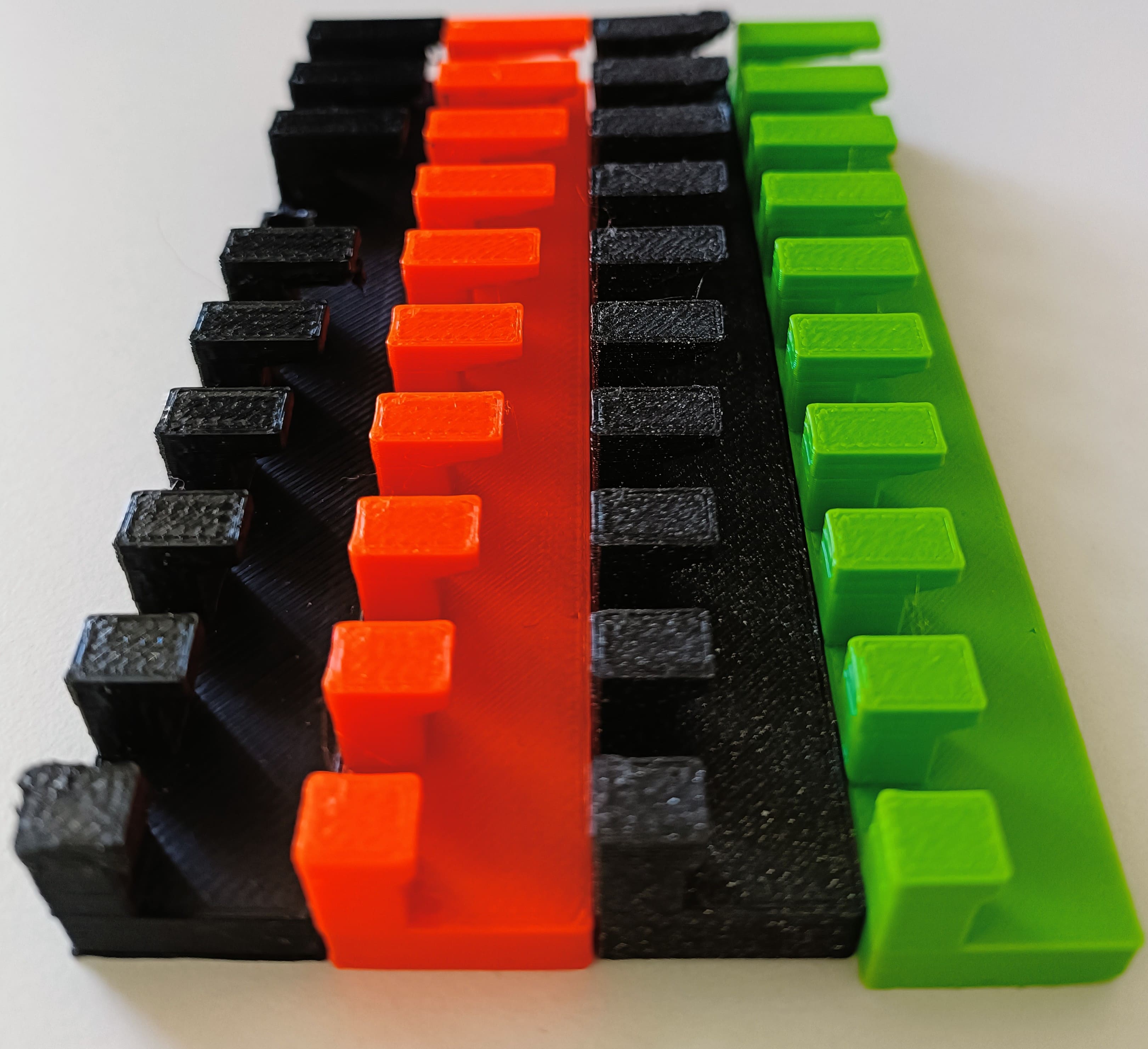
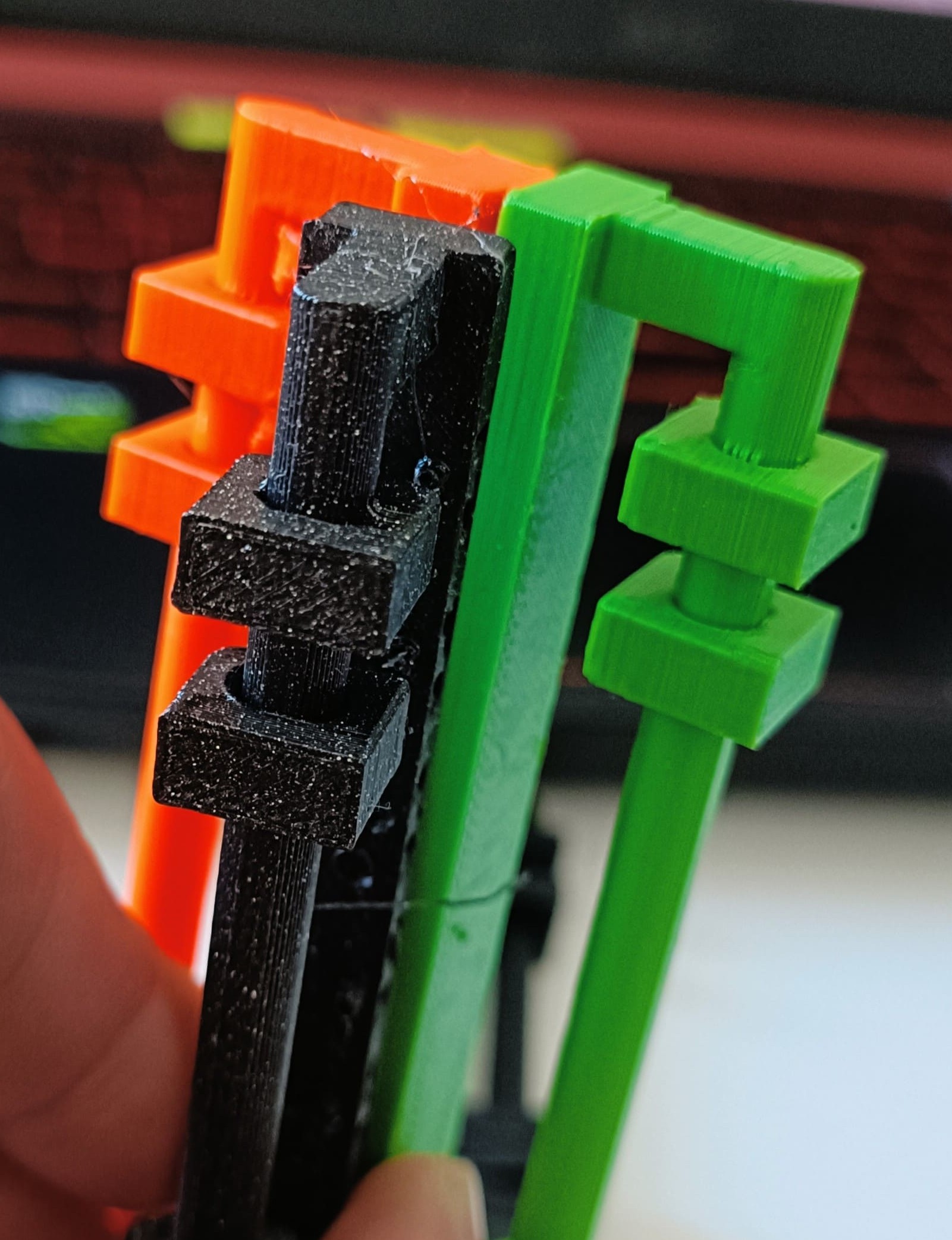
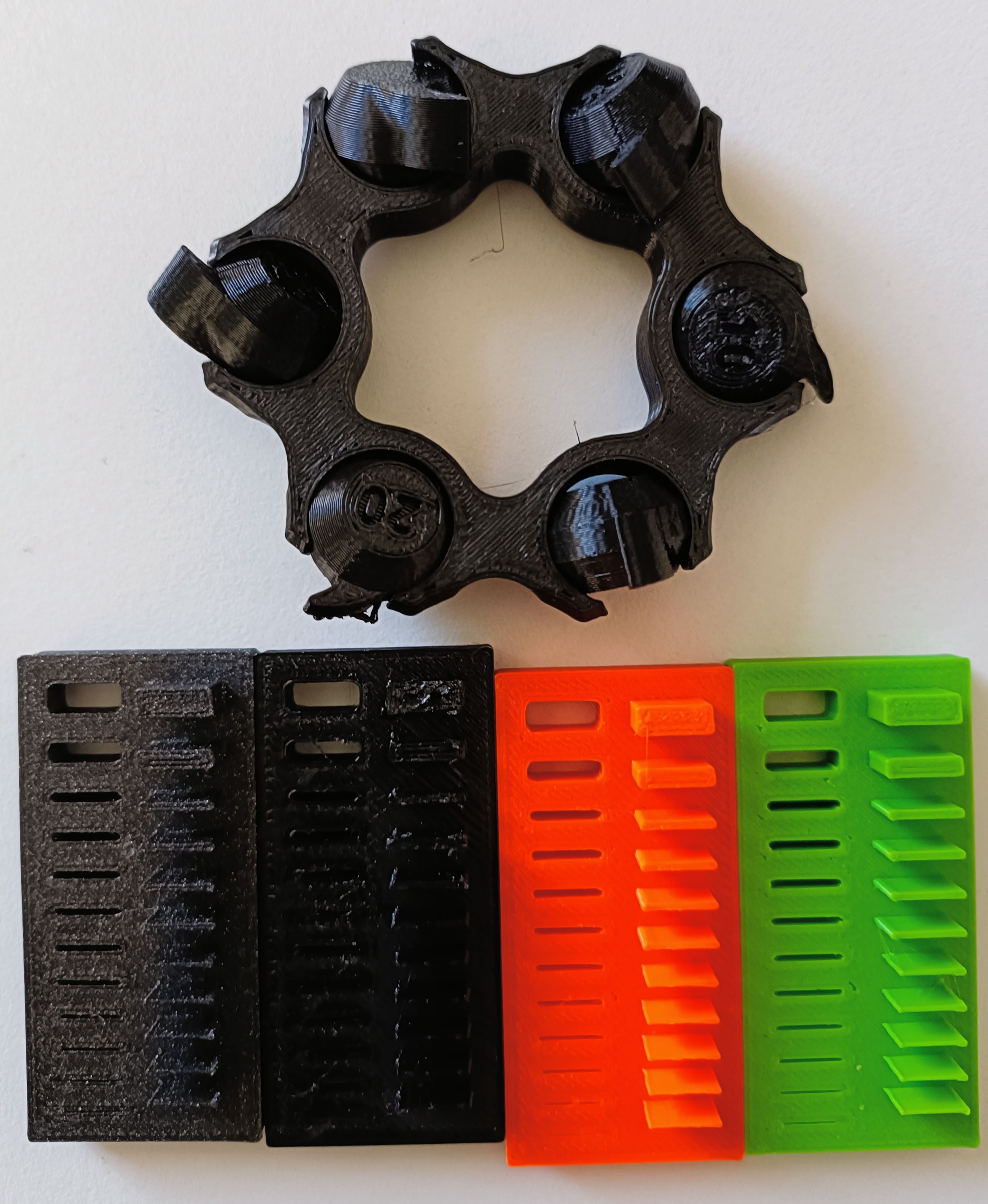
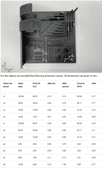
Findings:
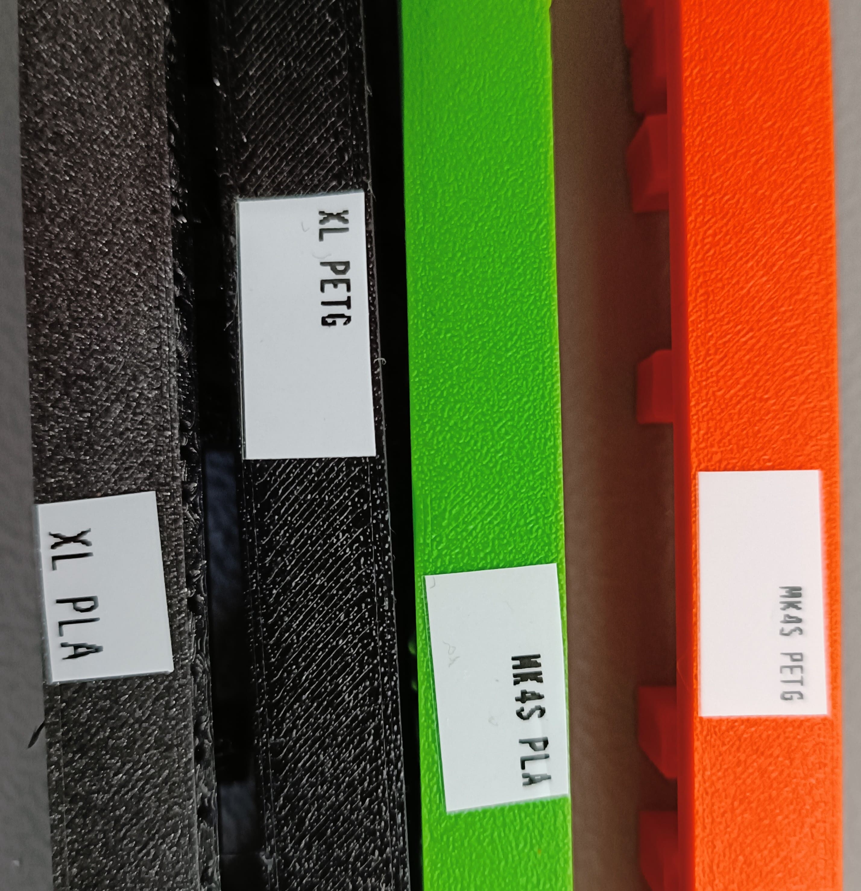
The test were done with the Prusa XL and MK4. Results from these test highly fluctuate when tested on other printers.
- The differences are about 0.2mm.
- The bigger the object, the bigger the differences. Prusa XL PETG was off
- Steep printing without support: 30deg recommended, up to 50deg precise, 60deg with tolerances.
- Bridges without support: 25mm (maximum test length) works splendidly.
- Surface finish looks goo on every angle.
- Min. limit on wall thickness: 0.34mm to 0.37 depending on printer and filament.
- Try to avoid 90deg overhang in any length.
- Tolerance: Min. 0.3mm if it should move. 0.2mm for semi strong connections. 0.1mm if the connection should be tight.
Comparison slicing software:
I wanted to know which software (and printer family) is the best from the ones I have access to: Orca (Flashforge), Prusa (Prusa), or Cura (Ultimaker)
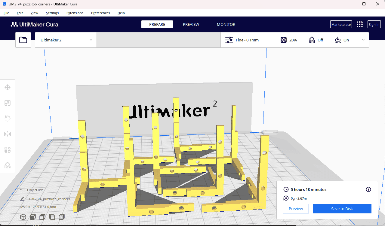
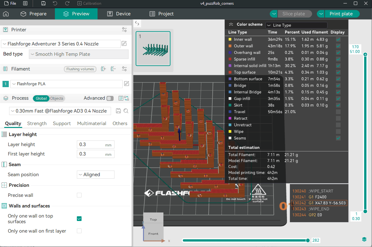
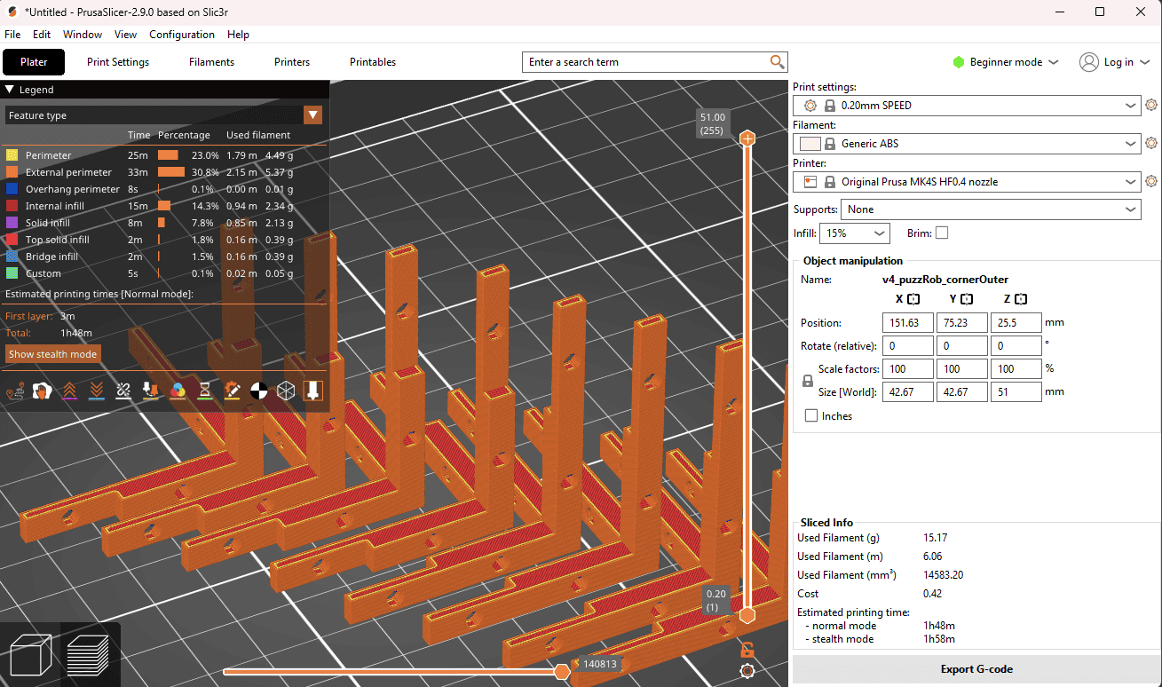
I tested with the same model and same parameters (as much as I could). Cura refused to print in the formation shown in the other 2 examples. It was also the only one that could not deal with the closeness of the parts. Orca also threw a warning but allowed exporting the gcode nonetheless.
3D Scanning
We decided to fix the broken lab glasses for one of the glasses of a befriended lab.
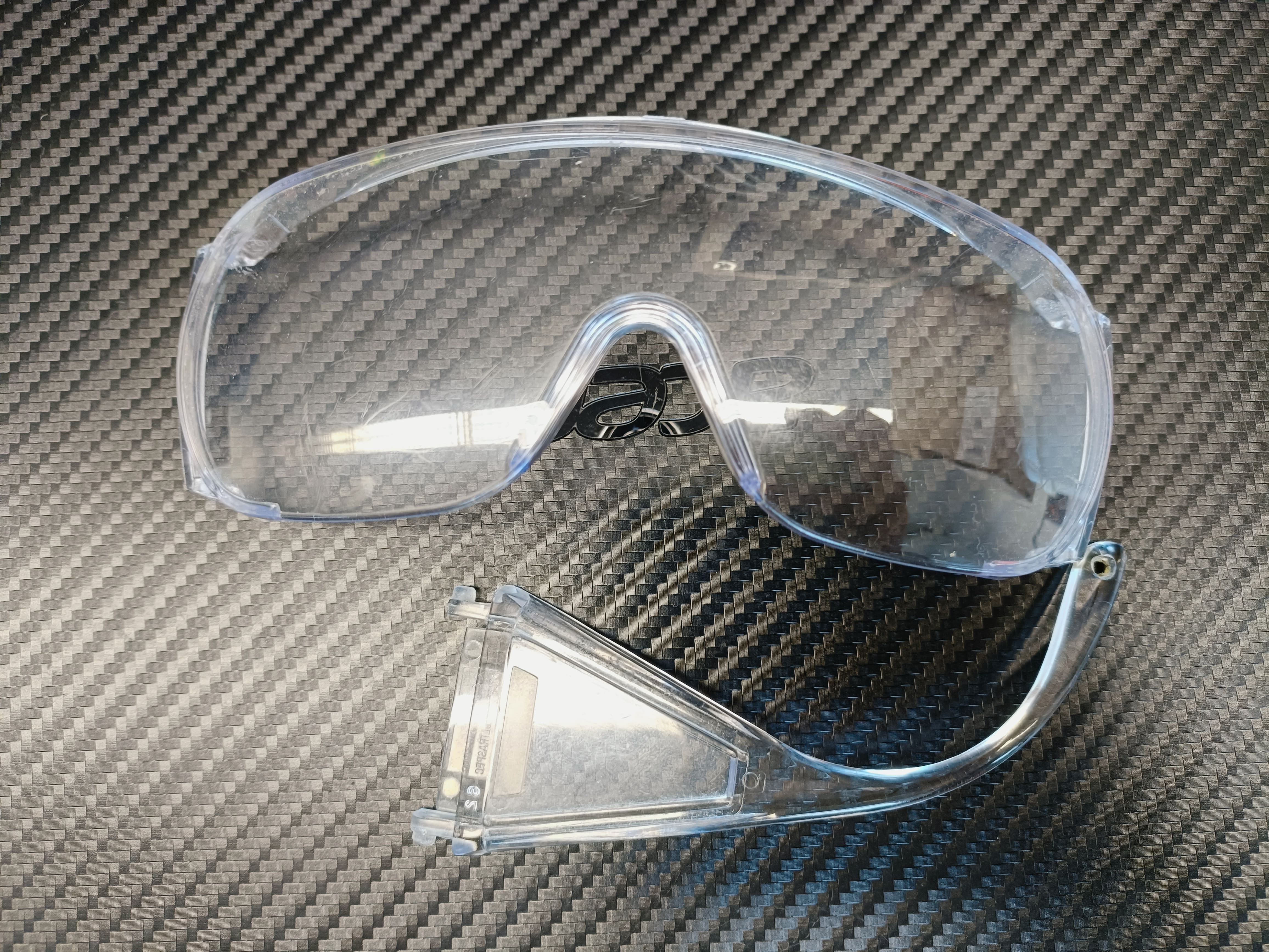
- The glasses were see-through. This would have caused issues with the scanner, so we sprayed it with specialized scan paint.
After letting them dry for a day, they were ready to be scanned. Unfortunately, whenever one touches the glasses,
the spray color comes off.
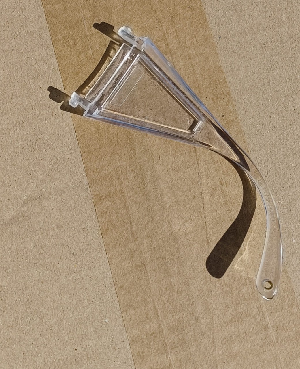
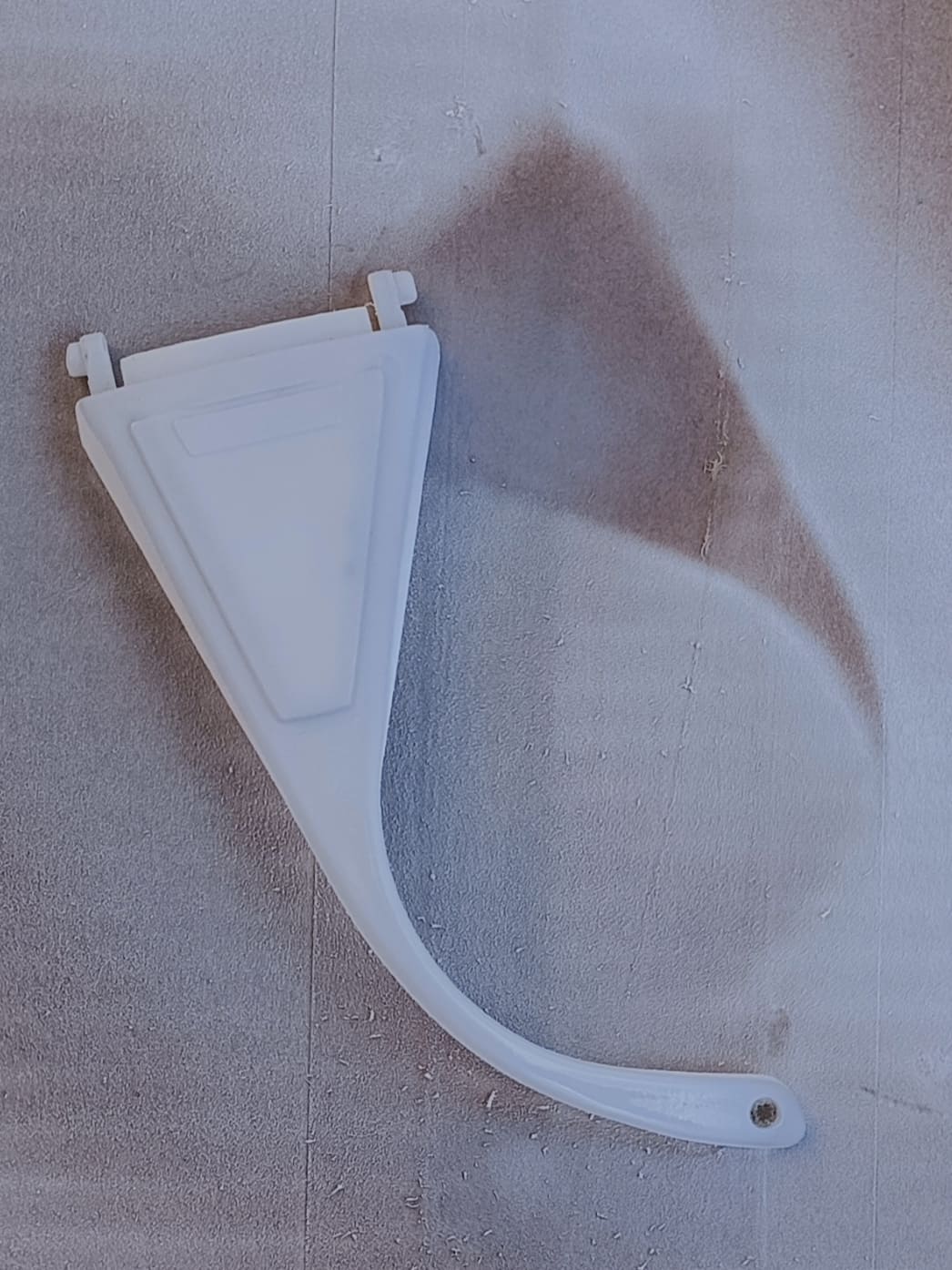
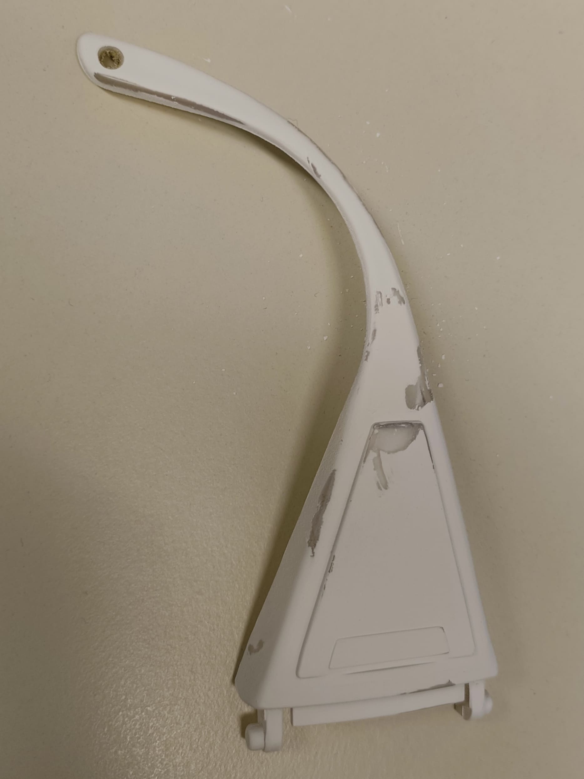
Left: See-through broken lab glasses piece. Middle: result after painting. Right: the color comes off wherever its touched. - We went ahead with it anyway. We then placed the beacons in a wy that at least 4 black dots can be seen from every direction
just like in the picture below. In case the scanner can not see enough beacons at any time, the scanning process is paused.
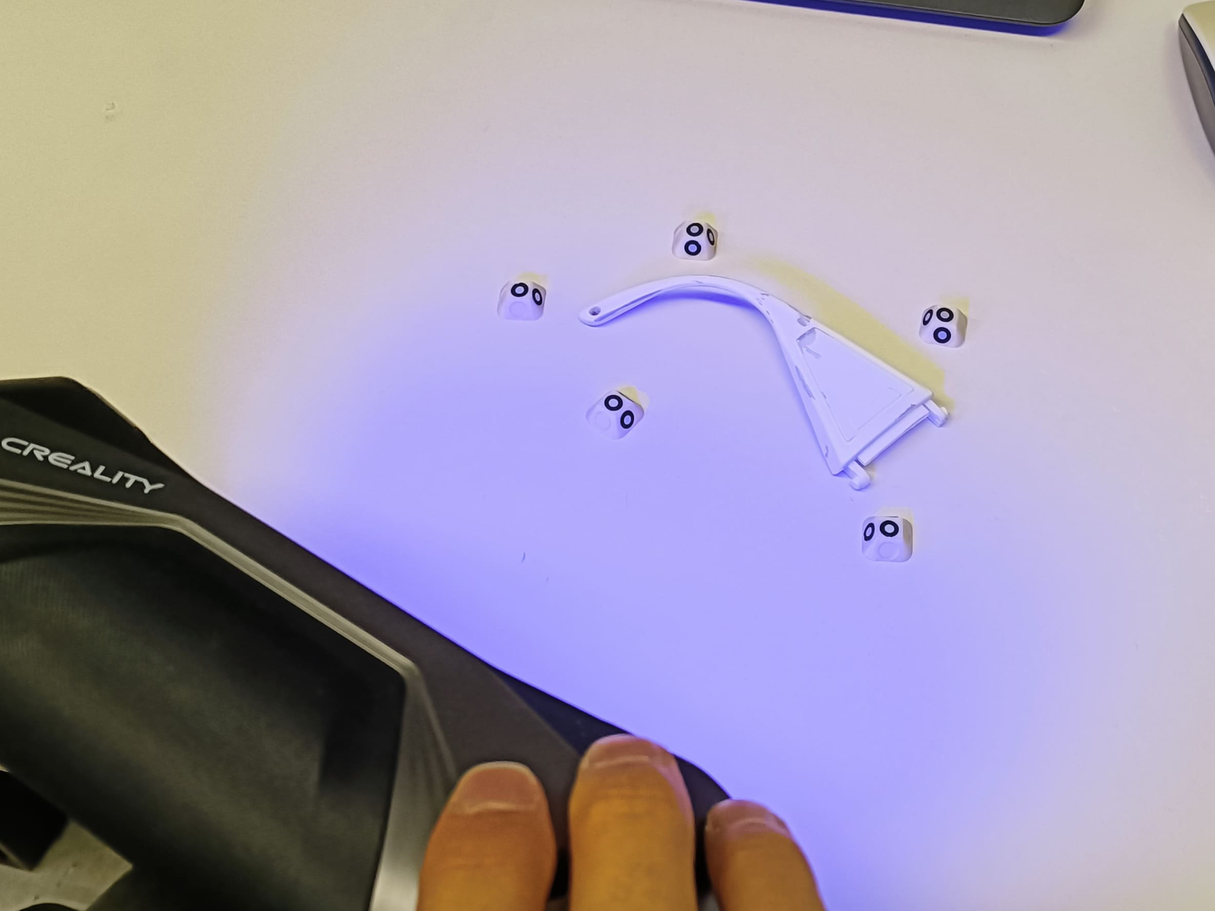
Positioning the beacons in a way that there are at least 4 black points always pointing in every direction. - The software were using is the Creality Scan
and the the device a Creality Raptor.
To connect the scanner to the computer, connect the power supply to the power and the USB to the computer.
In our computer, it has to be on the first USB slot, otherwise the scanner is not recognized.
The connection to the glasses are achieved by plugging in the micro hdmi to the glasses and screwing it close just lie in the picture:
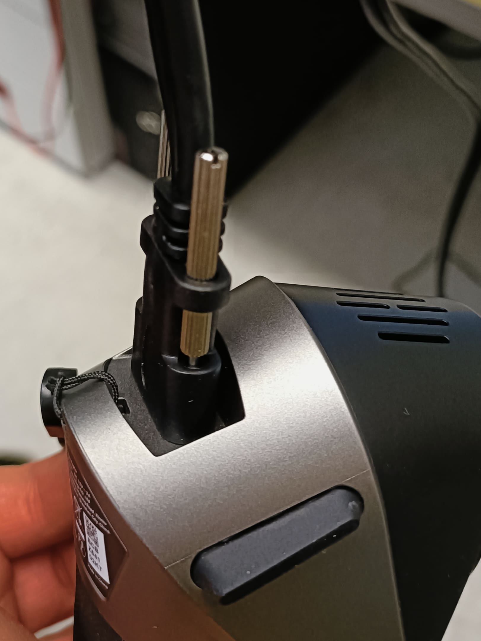
Right way to plug in the 3D scanner - In the software you will be greeted with 2 options: Blue light (BL) and Infrared (IR):
- IR
- Structured light scanner
- Can do textures
- Only black and white
- Used for big, unprecise objects
- BL
- Time of flight laser scanner
- No optic tracking, orientation only through beacons
- Creates a 3D mesh
- Use for small, precise objects
We used BL with the settings geometry and flat base off. However, leaving the flat base on does not change anything.
- When ready, press the "play" button on the camera and gently move the scanner around the object.
Try to always maintain the same angle. Whatever happens, the software will tell you what to do.
Once you're done scanning the entire picture, it will look a bit like this:
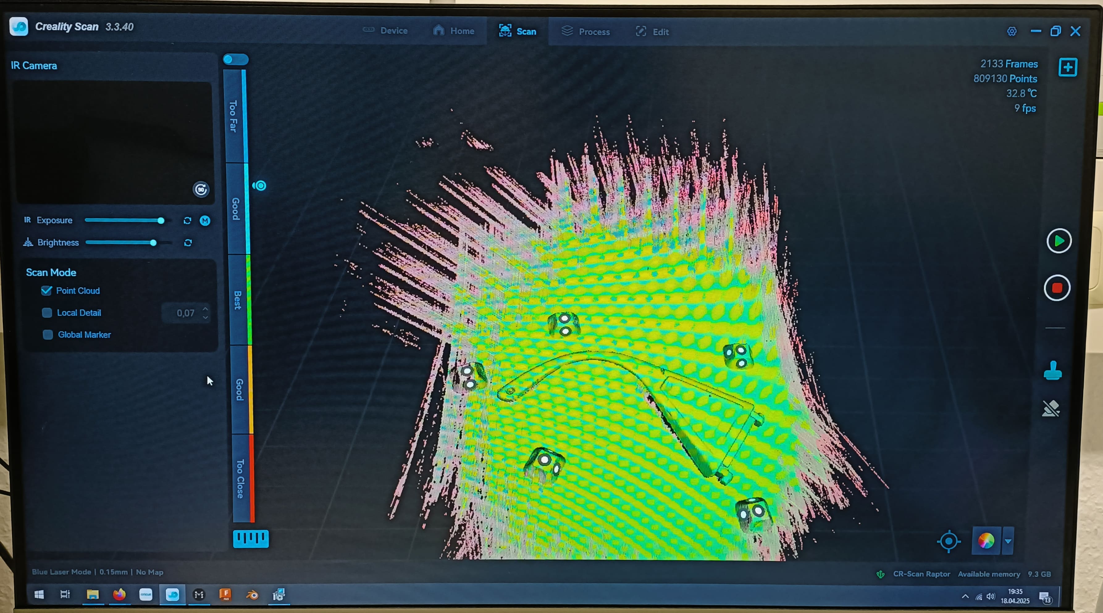
Scanning menu Warning: you have to be very patient.
- In the menu on the left side click on the uppermost option. This will be for initial processing.
Once the computer finished computing, the image will look like in the picture below. You can now cut away all
the scanning surfaces that are not part of the object using the magic lasso.
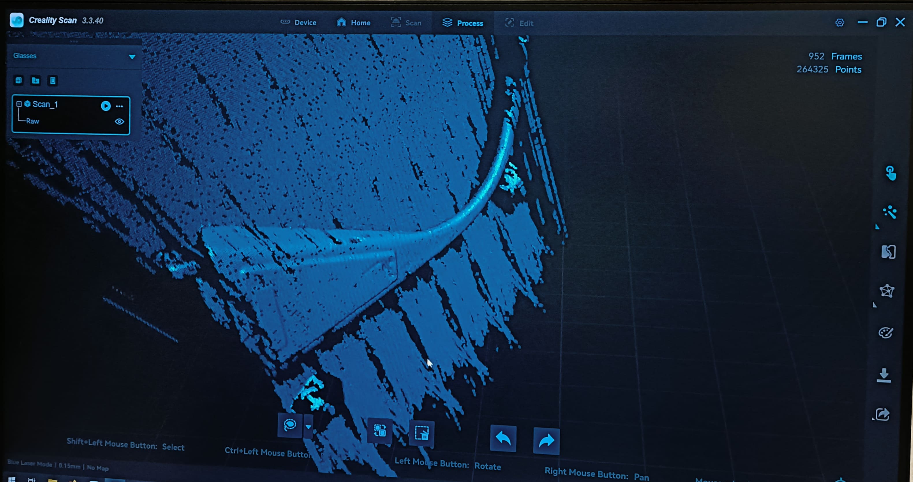
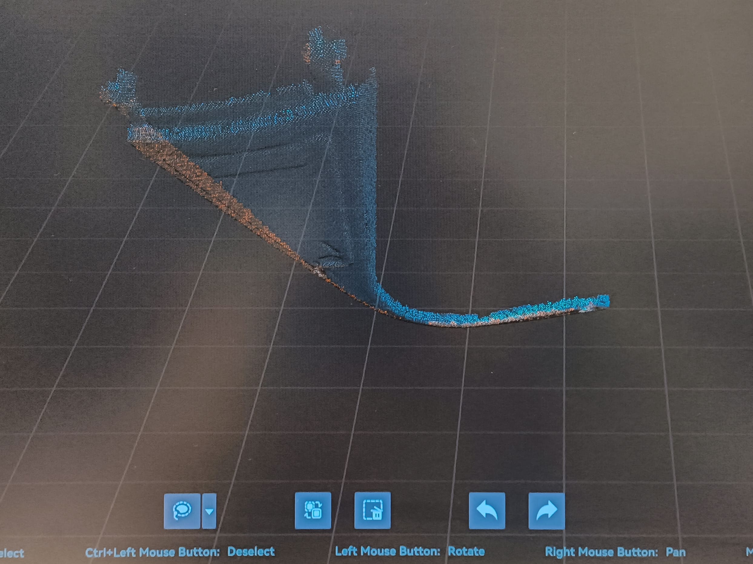
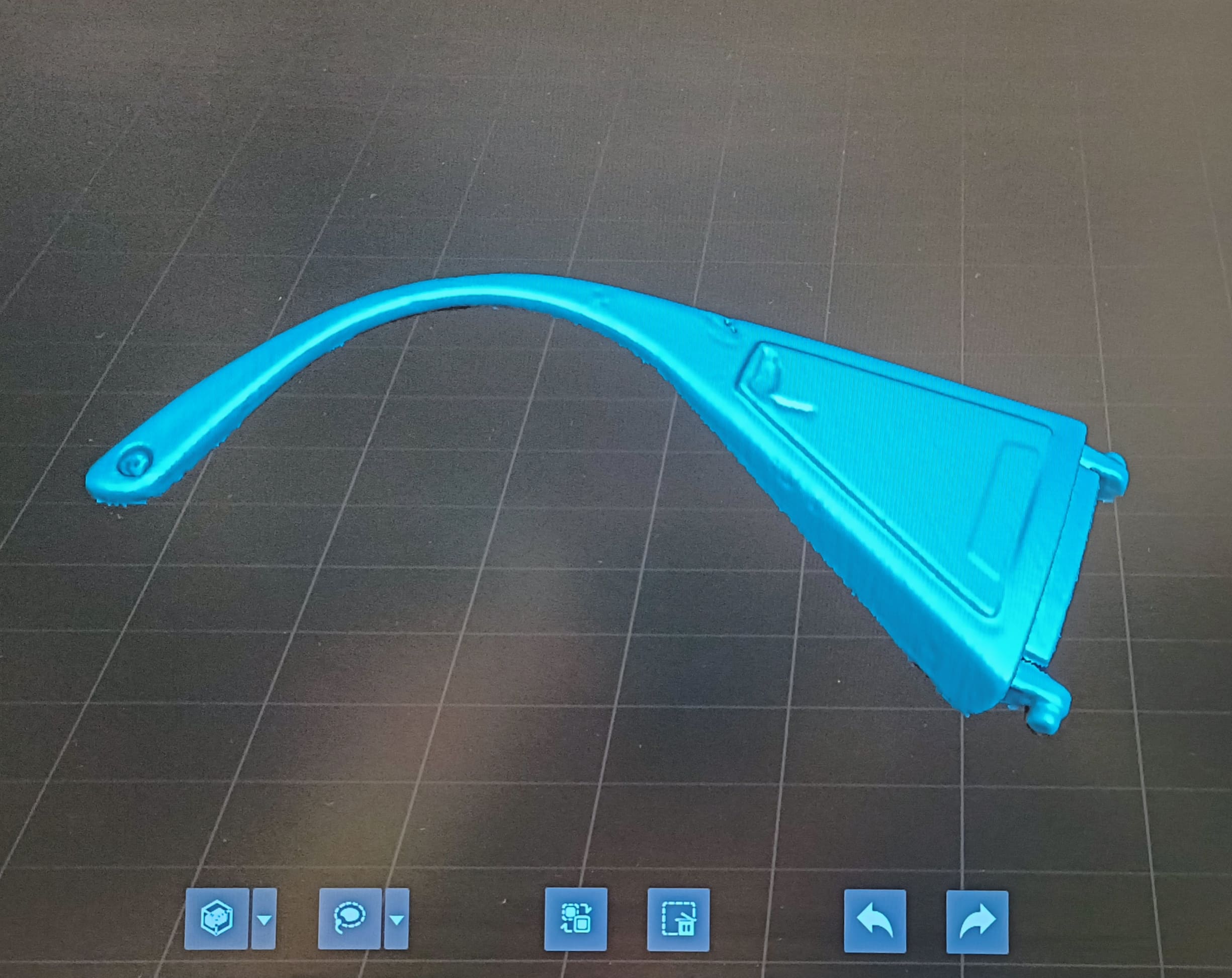
From left to right: processing chain - On the button directly underneath the "create mesh" one there is an export button. It will prompt you to select a location
where to save it to. You have the option to export it as a stl, obj, or ply file. This is mine:
Note: keep in mind that the permission to save the file to a directory on your computer is very limited. As a result, the file might not show up in the file explorer. Just save it somewhere else until your computer allows accessing it.