Tasks
- ✔ Model (raster, vector, 2D, 3D, render, animate, simulate, ...) a possible final project.
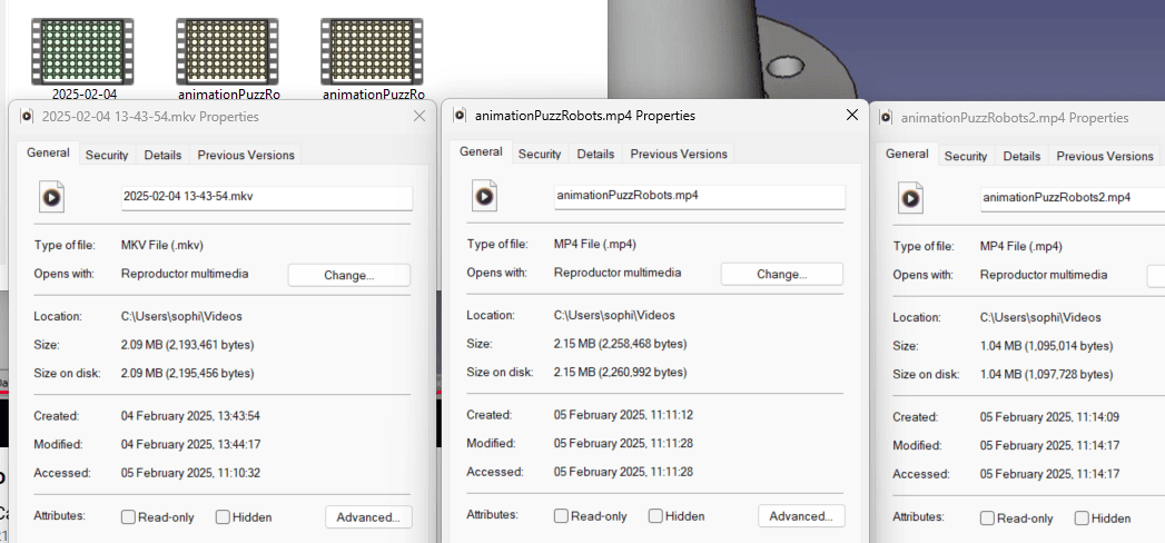
- ✔ Compress your images and videos.
- ✔ Post a description with your design files on your class page.
- ✔ Test as many different software as possible.
Conclusion
CAD files (.3mf) for download:
Issue: Duplicate a component and assembly in FreeCAD
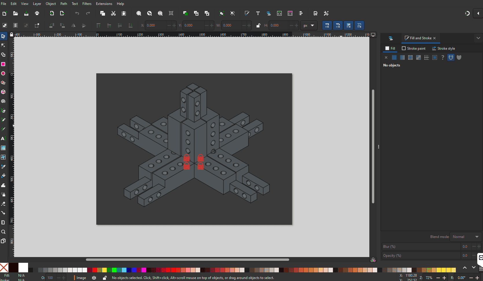
Initially, I designed only one side of the modular corner. I copied that body and rotated it accordingly to achieve that pyramidal/ 3-finger-rule shape. When I tried inserting that part into the assembly workbench in FreeCAD, I was surprised that only the initial part of the pyramid was inserted. I tried the following things to duplicate it:
- Copy/paste the shape. Chaos ensued.
- First create a solid body out of the 3 fingers and then insert that into the assembly. Kind works but not really.
- Manually insert 3 fingers and then copy that using the "Draft" workbench. Kinda worked.
Only the third option kinda worked. The difficulty lies in finding the right center to rotate it around. It would have been ideal if I could I have inputted the values from the spreadsheet. That did not seem possible though. Still working on finding a viable solution.
For now, the assembly (v1) I have right now already helped me find an issues with the current design:
- The holes in the wide part need to be towards the outside to attach the connector walls to it.
- The connector finger to the next modular corner can be wider to maximize stability.
Making digital design on FreeCAD
Before this week, I I hadn't used FreeCAD before. However, being experiences with Autodesk Inventor and Fusion 360, it was a very natural workflow.
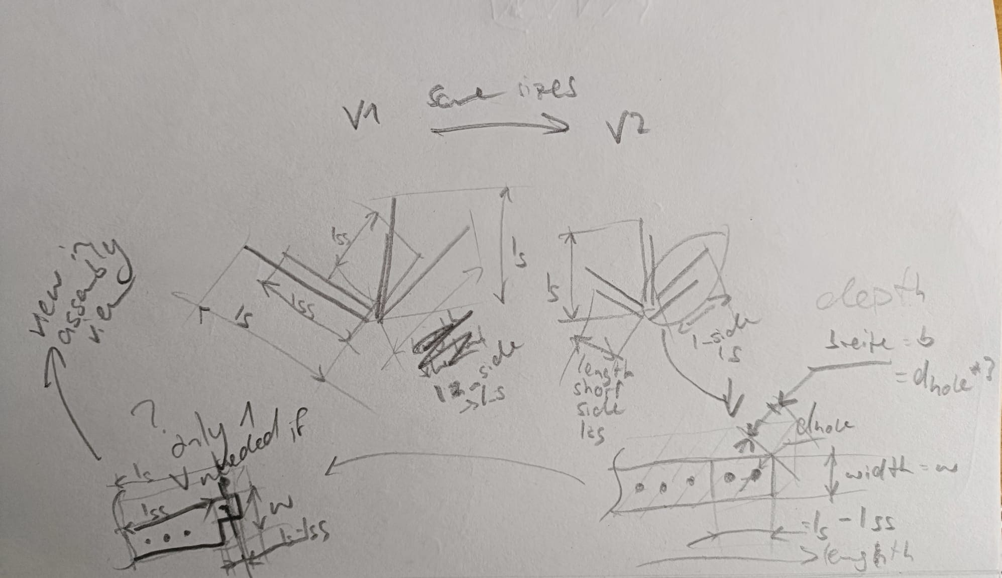
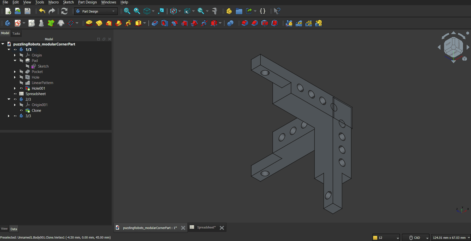
The final outer shape of each puzzling robot will be a cube with a button on top. I decided to have modular, parametric corners that I can alter in length and width according to what I see fit. I will be adding the outer wall and connection mechanisms during a later assignment. The holes fit screw nuts to later connect the pieces with standard norm screws.
The following tutorials have helped me at some point during the design process:
- FreeCAD Spreadsheet
- Constraints between sketches of different bodies
- FreeCAD linear pattern tool
- Difference between FreeCAD Clone and Link tool
- FreeCAD multi clone workflow
- Introduction to FreeCAD part 2
- Topological naming problem FreeCAD
- Export FreeCAD to STP file
Some of these videos contained general advice on 3D modeling. Though I had already been doing most of them, I never wrote down rules for it. I found them really useful and will incorporate into my designs from now on.
-
2mm walls for stability
, Source -
The goal is to have every sketch fully constraint
, Source -
To comfortably insert the SD cards, add 1mm to the measured sides
, Source
Finally, these are the CAD models from FreeCAD. I compressed them exporting them as .3mf files.
Due to some fixes needed in the design, its version will keep being updated on the final project page.
Alternative Designs
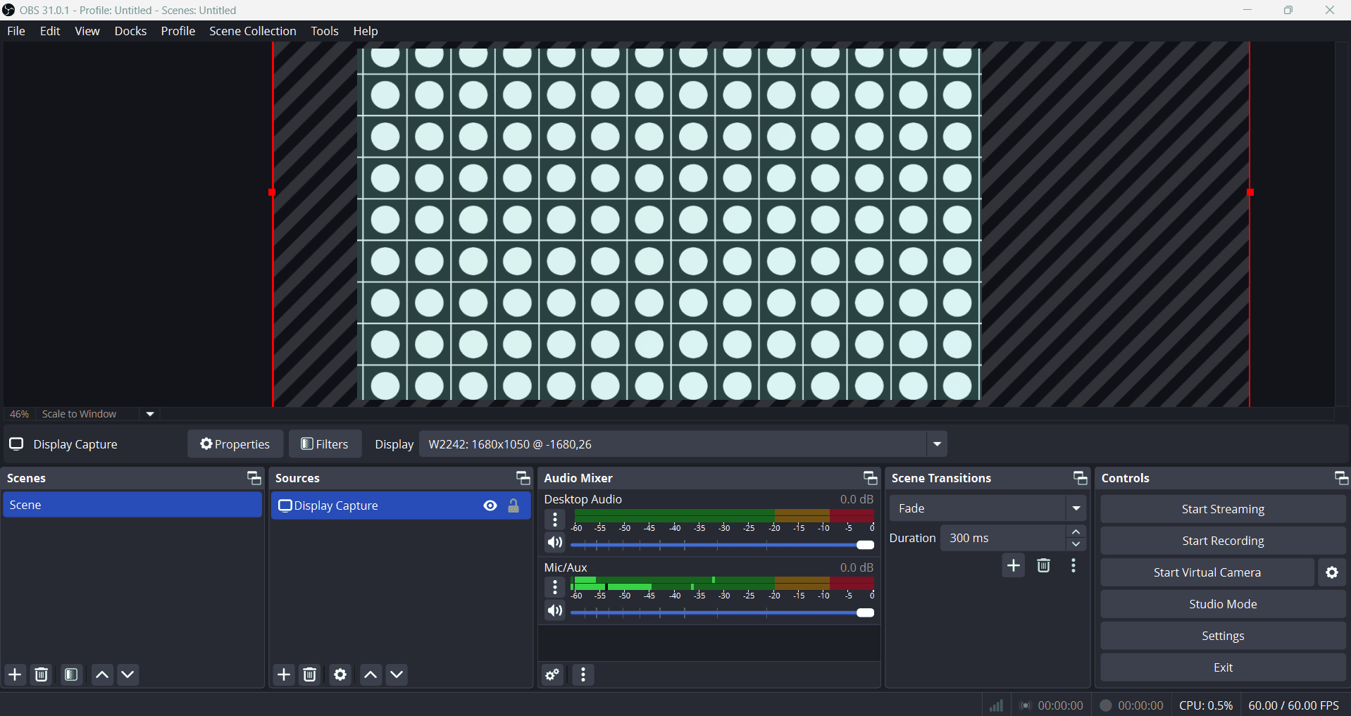
I wanted a vision on how the separate robots will look when combined. Because I already had the vision last week I made it using html, css, and JavaScript. The initial image was created using Krita and this Codepen tutorial showed me how to do the animation. As always, I used Visual Studio Code to program it and Live Server for previews. This time I recorded the animation using OBS Studio and compressed it using HandBrake and this tutorial. The screenshot was taken using Snippet Tool and all images were compressed using this website.
What I want to improve next week
- Get started earlier
- Focus on actual task
- Website: get navbar working properly, change font (to Roboto)
- Nice to have: Do proper documentation on design of puzzling robots modular (possibly even in Latex)