1. Computer Controlled Machining
This week, I designed a bookshelf using FreeCAD and fabricated it using CNC machining. The process involved careful planning, modeling, and execution to ensure precision and structural integrity. By following a structured workflow, I was able to successfully manufacture a functional bookshelf with interlocking joints and artistic design elements.
1.1 Safety Protocol
Ensuring safety is the first and most critical step before operating any CNC machine. The following precautions were taken:
- Completion of CNC machine safety certification training to understand machine operations and potential hazards.
- Reviewing emergency stop procedures and machine operating guidelines to handle any unforeseen issues effectively.
- Wearing appropriate personal protective equipment (PPE), including safety glasses, hearing protection, and closed-toe shoes, to minimize risks during the machining process.
1.2 Bookshelf Design (FreeCAD Workflow)
The design process involved breaking down the bookshelf into individual components, each carefully modeled in FreeCAD. The workflow ensured that all parts fit together seamlessly while maintaining a balance between aesthetics and functionality.
1.2.1 Backboard Assembly
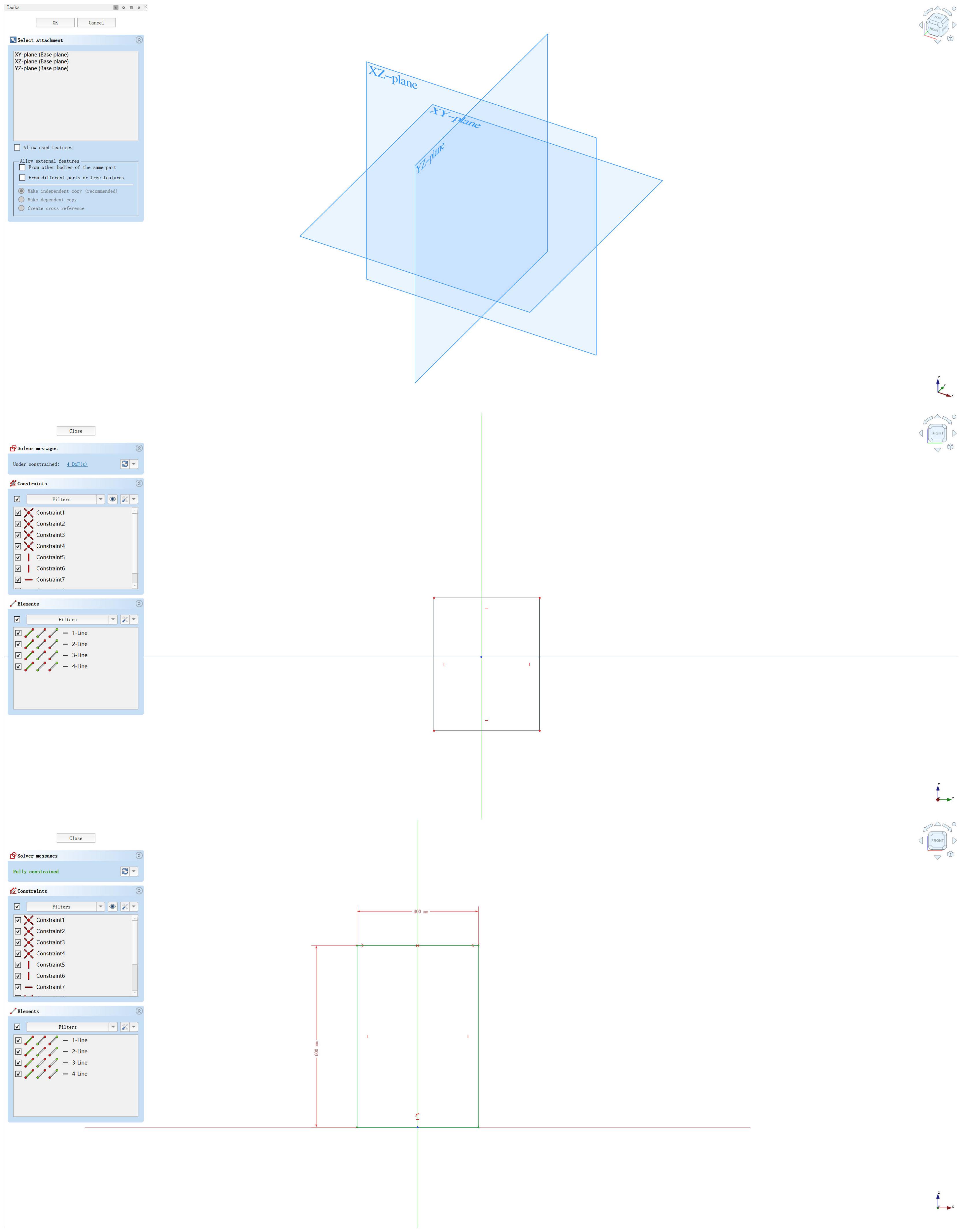
- Sketch Development
- A base sketch was created in the PartDesign workbench with precise dimensions (600 × 400 mm).
- Finger joint connections were incorporated to enhance the structural stability of the bookshelf.
- 3D Modeling
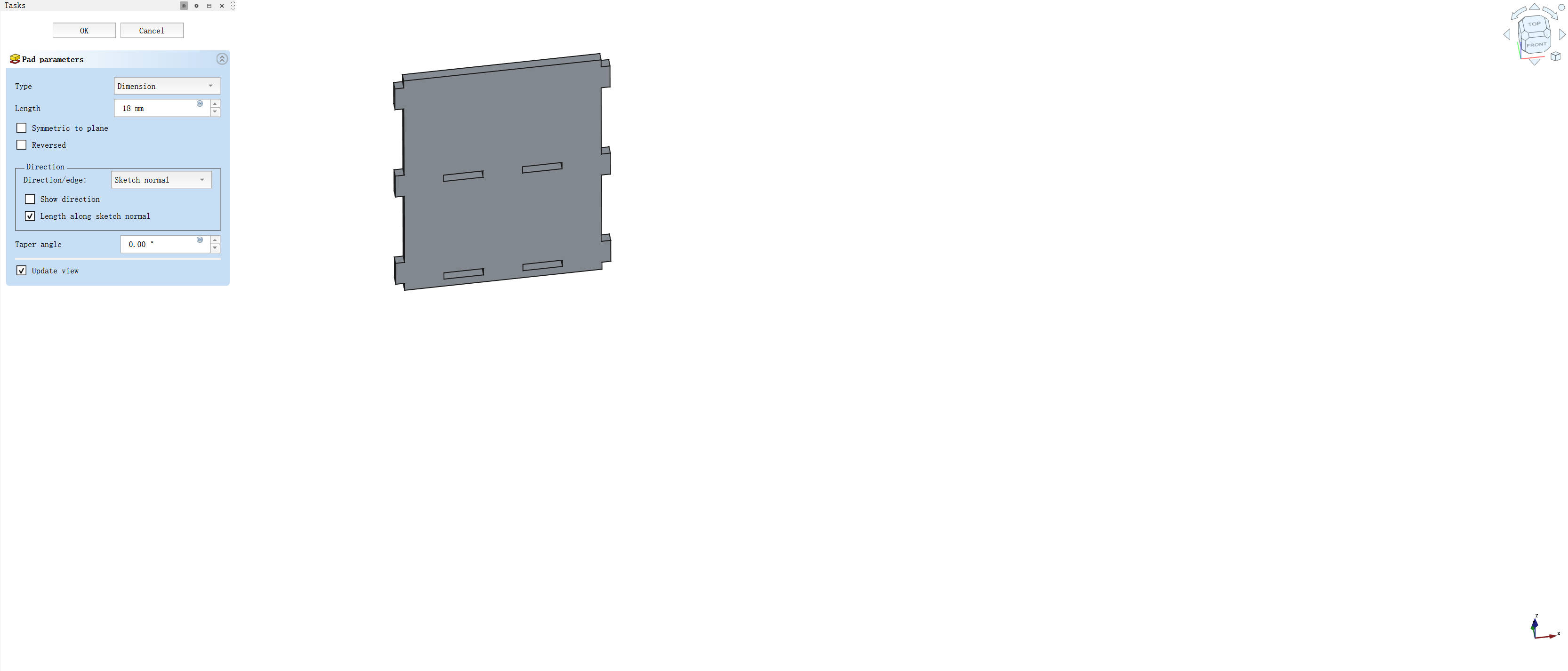
- The sketch was extruded to a thickness of 18 mm, representing the plywood sheet used in fabrication.
- Fillet edges with a 3 mm radius were added for a smooth and safe finish.
1.2.2 Side Panels
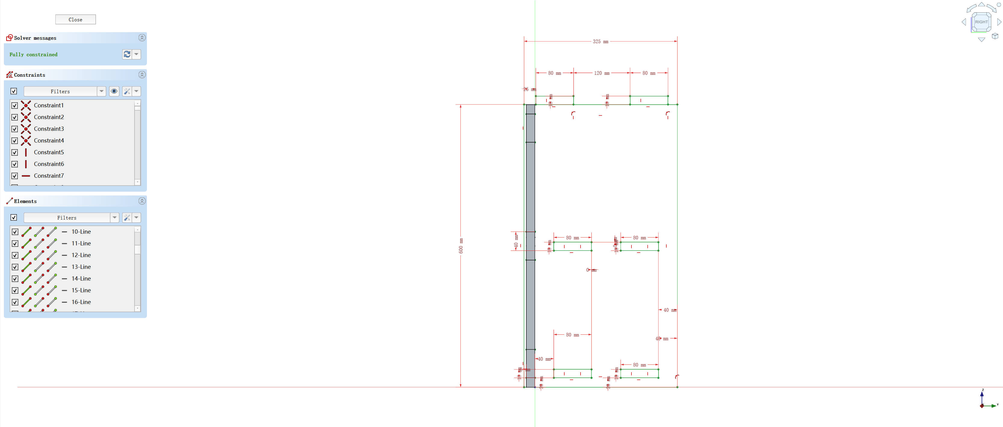
- Profile Creation
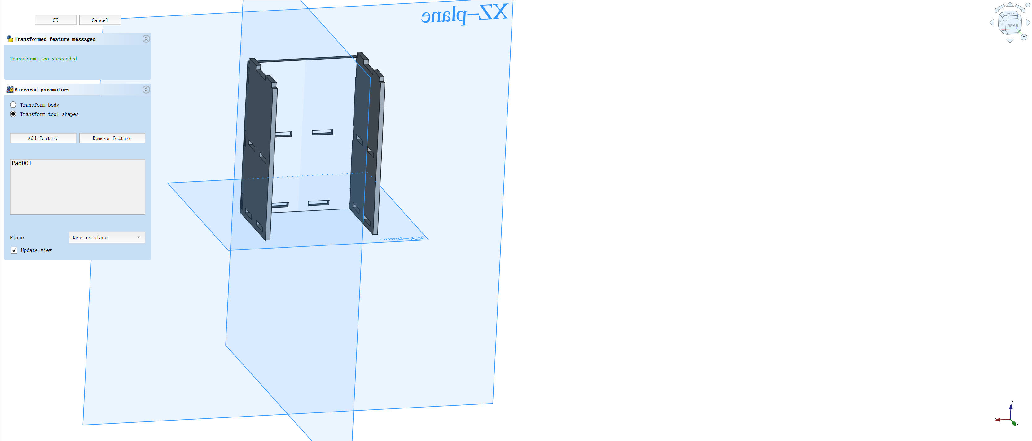
- The side panels were designed as mirrored sketches (600 × 300 mm) to ensure symmetry.
- Interlocking tabs were incorporated to improve the rigidity of the bookshelf.
- Model Generation
- The sketches were extruded to a thickness of 18 mm to match the material.
- Each panel was positioned alongside the backboard, aligning with the connection points.
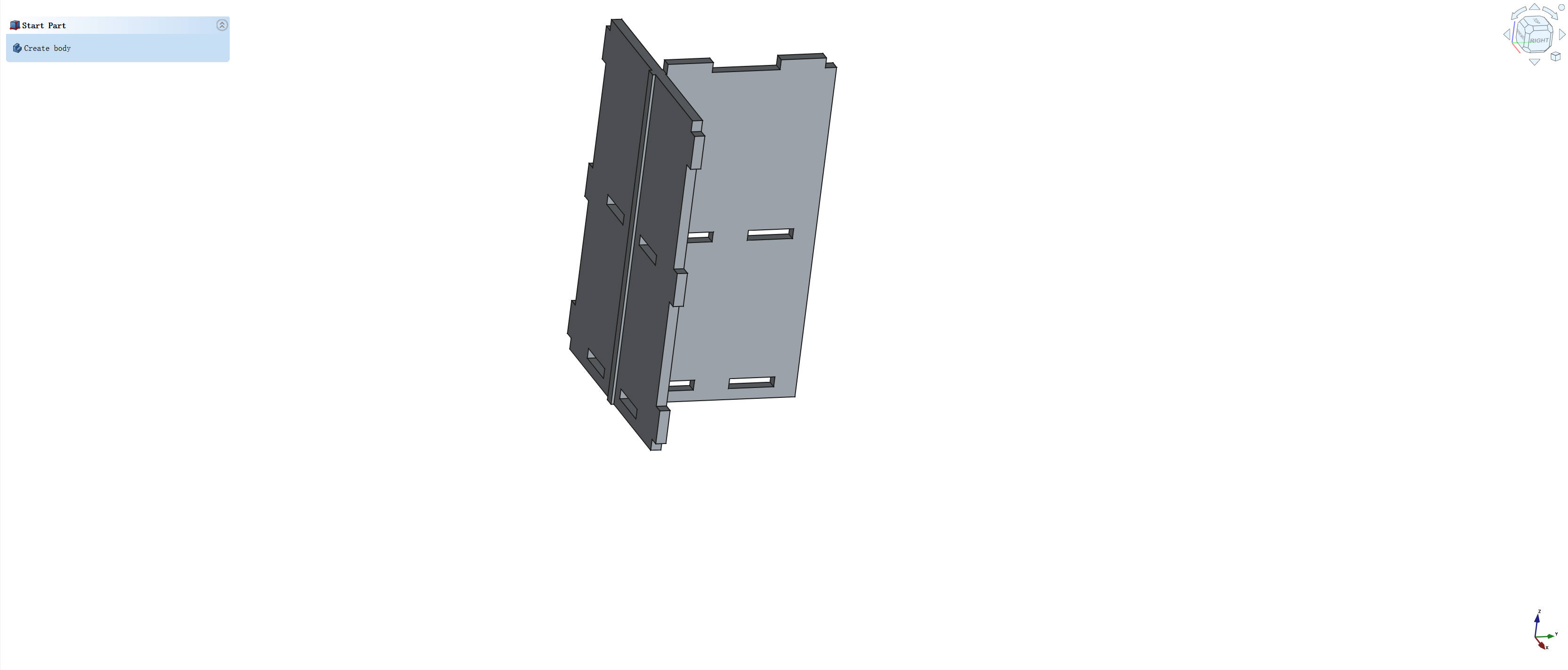
- The Mirror tool was used to create an identical symmetrical pair.
1.2.3 Top Plate
- Sketch Design
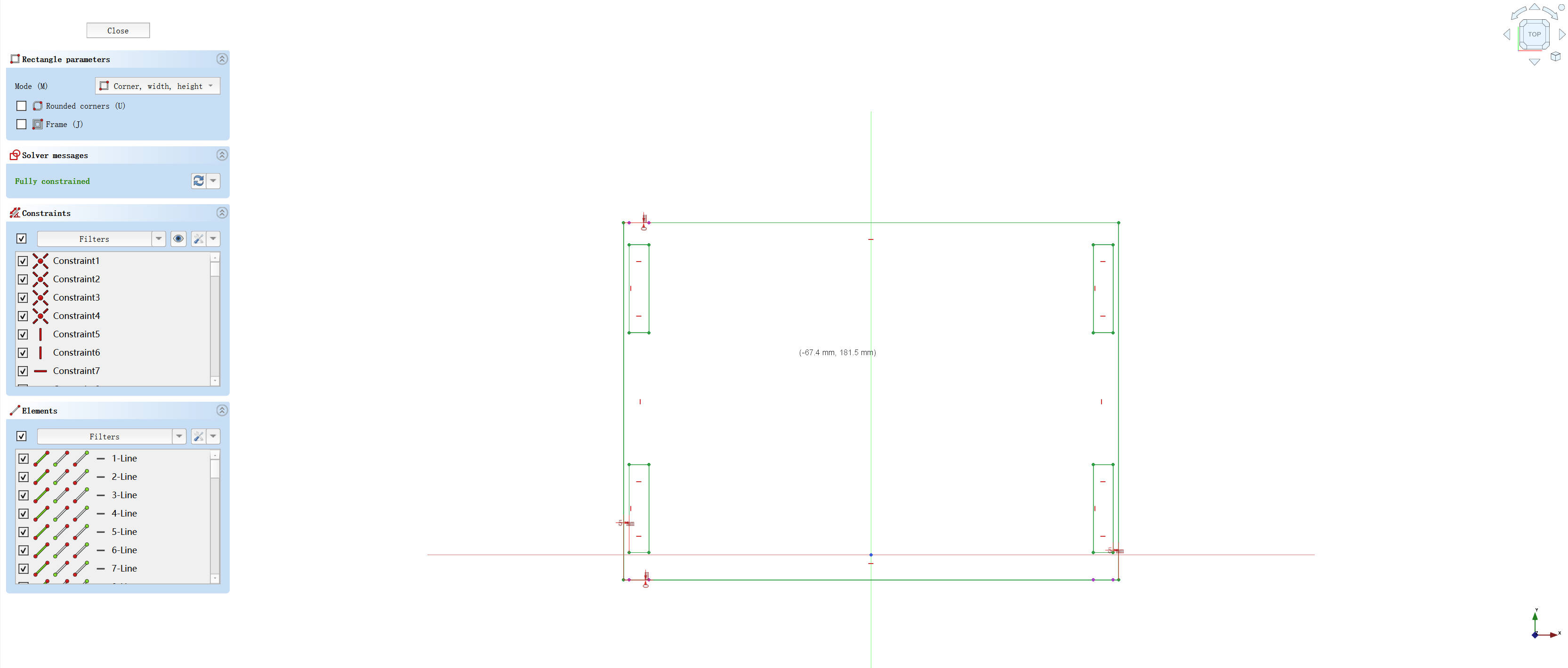
- The top plate dimensions were set to 325 × 400 mm to fit seamlessly with the side panels.
- Dado joint features were added to provide a secure and stable connection with the bookshelf structure.
- 3D Conversion
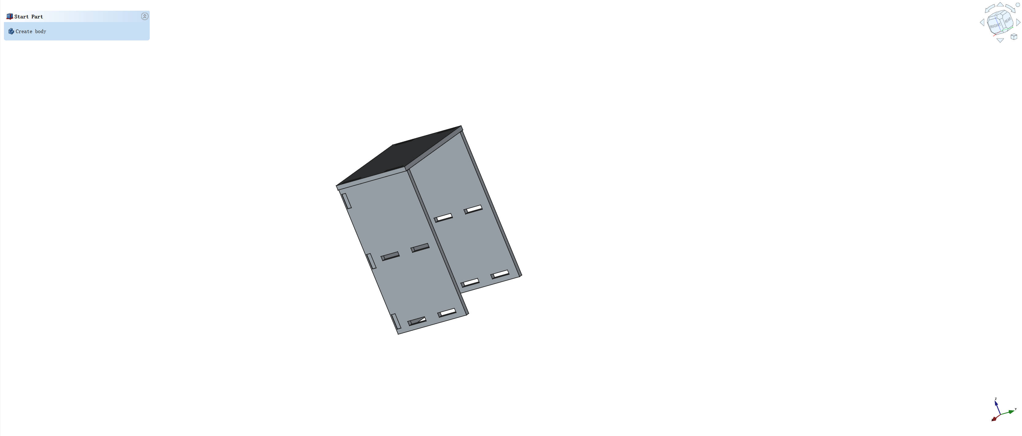
- The design was extruded to 18 mm thickness, maintaining consistency with other components.
- Pilot holes were added for easy hardware installation if needed.
1.2.4 Art Designs
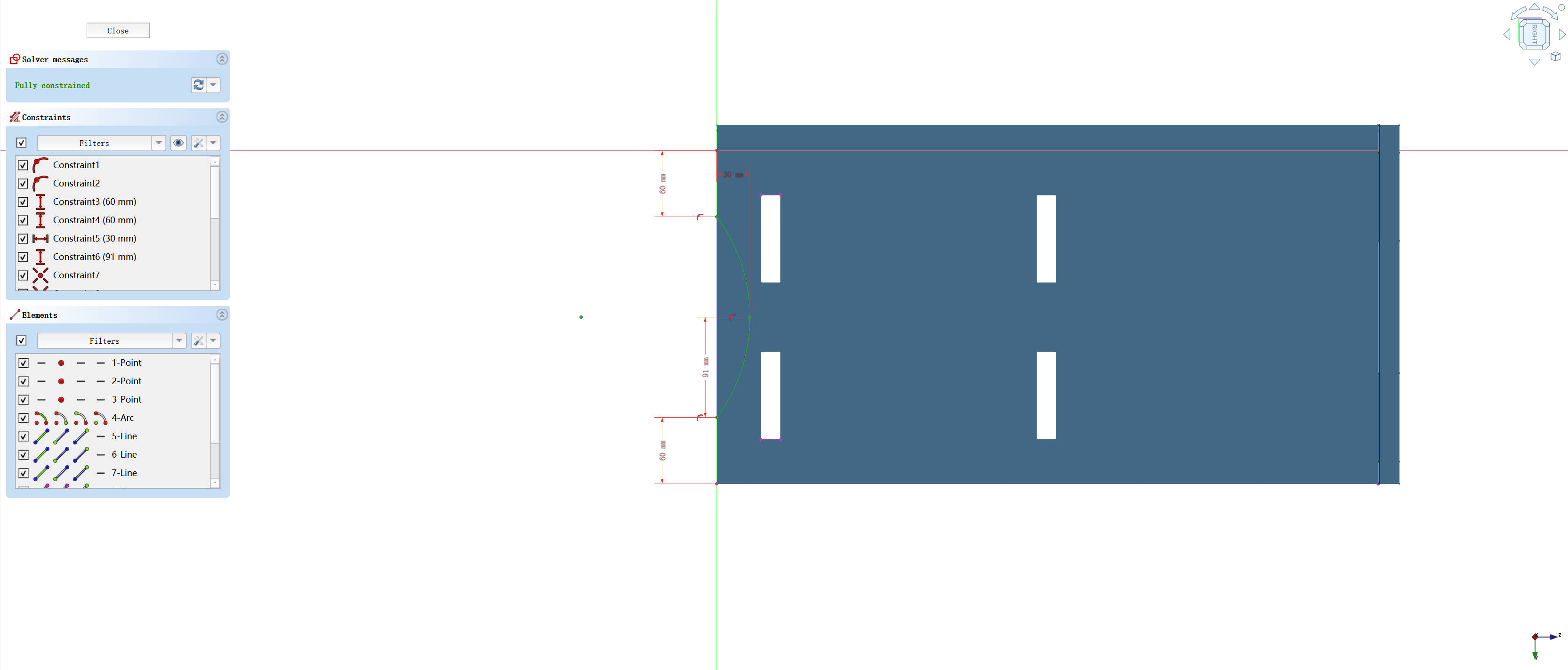
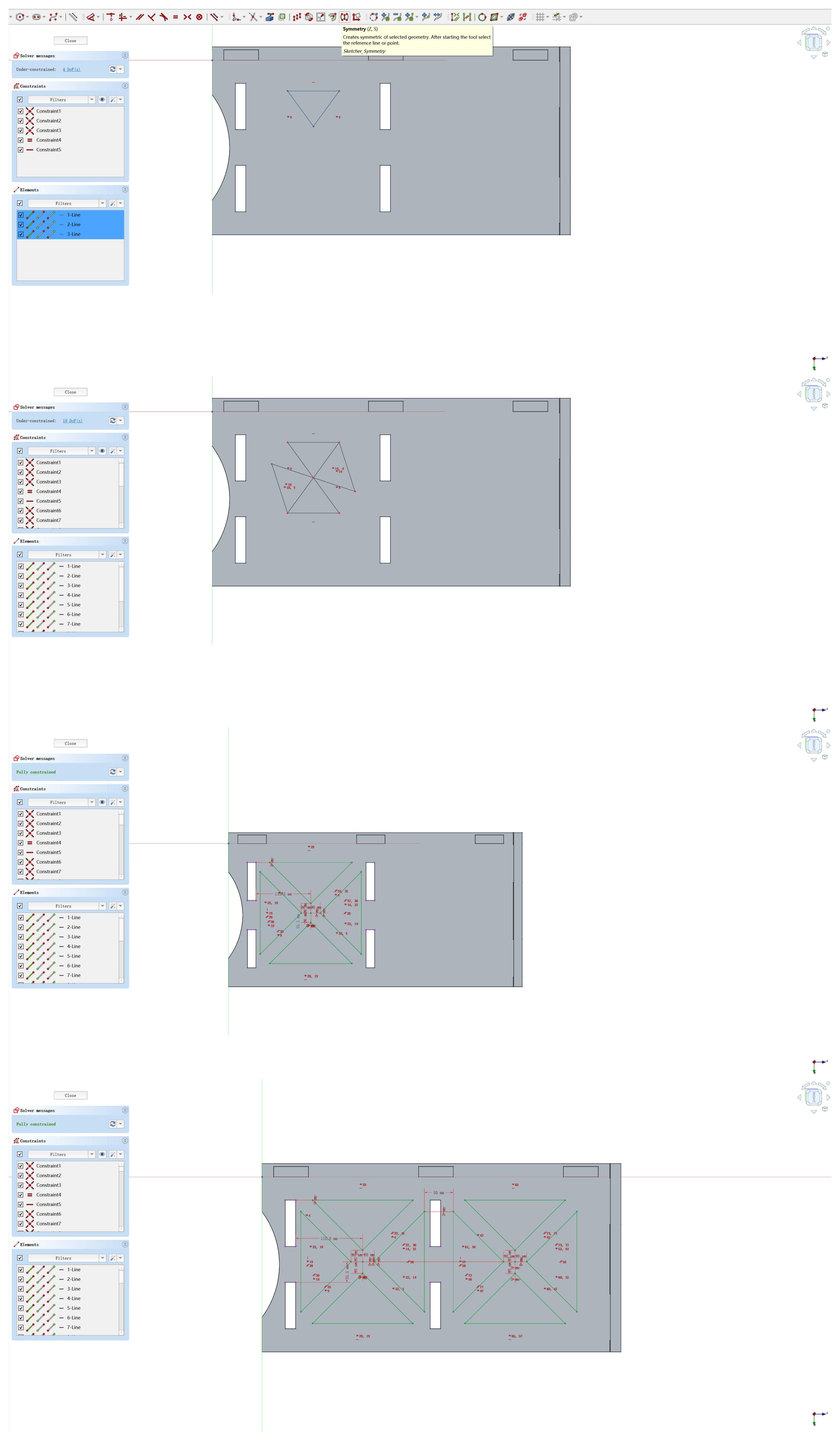
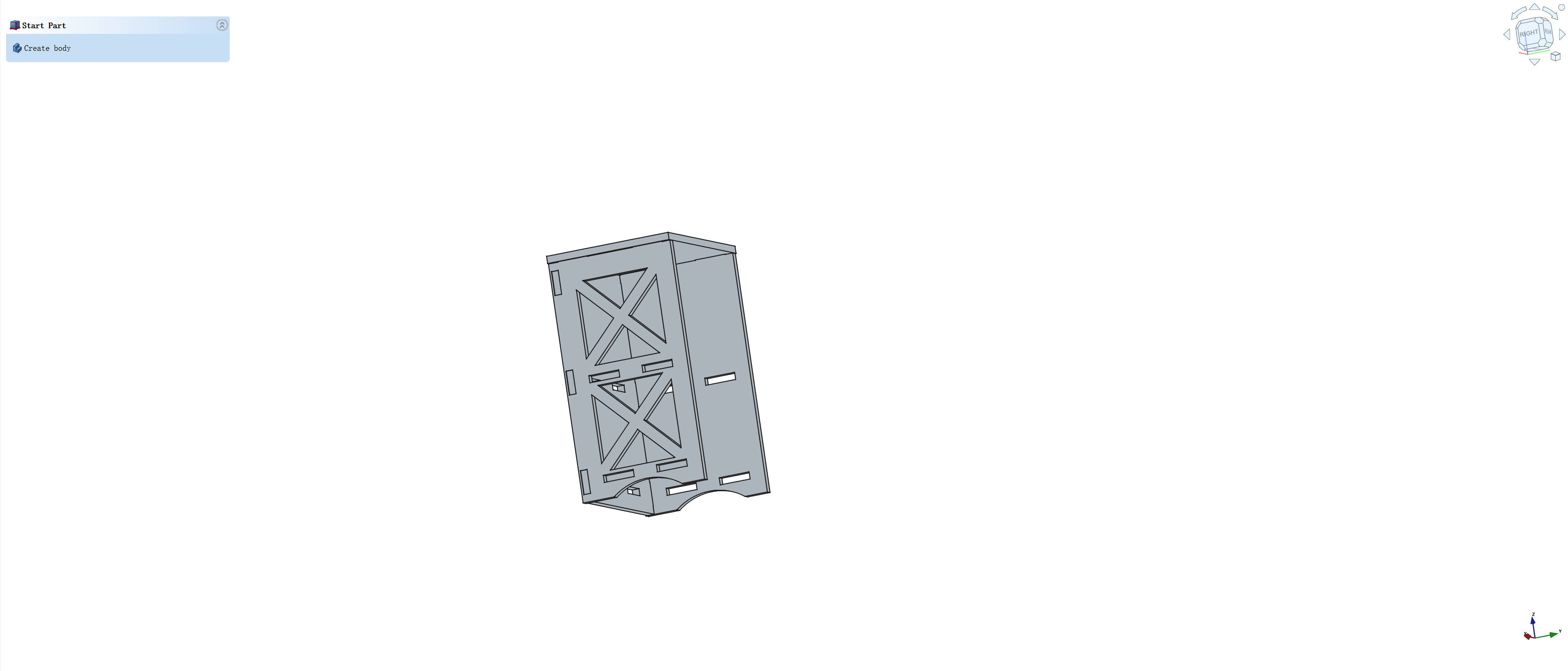
To enhance the bookshelf's aesthetic appeal, different artistic design elements were explored and integrated into the structure.
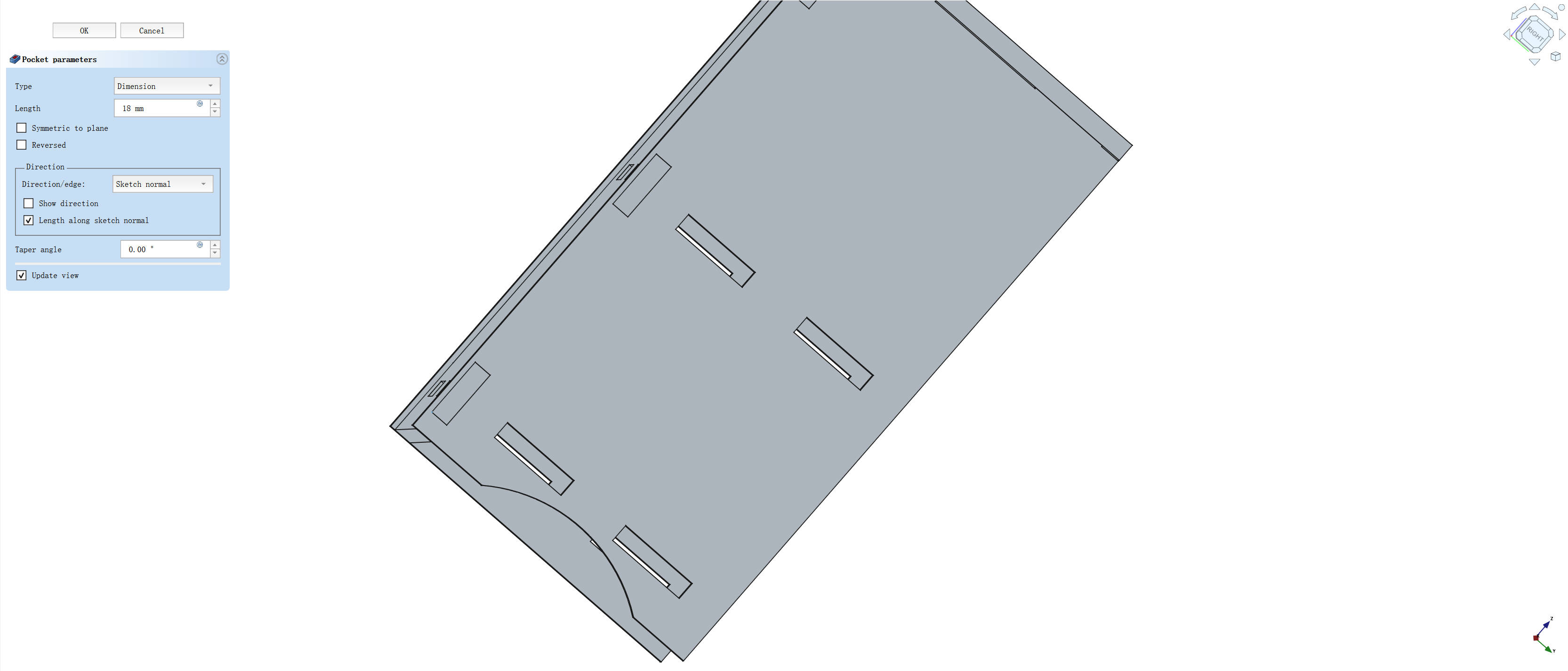
- Curved Design
- Skeleton Design
1.2.5 Shelf Components
- Base Sketch
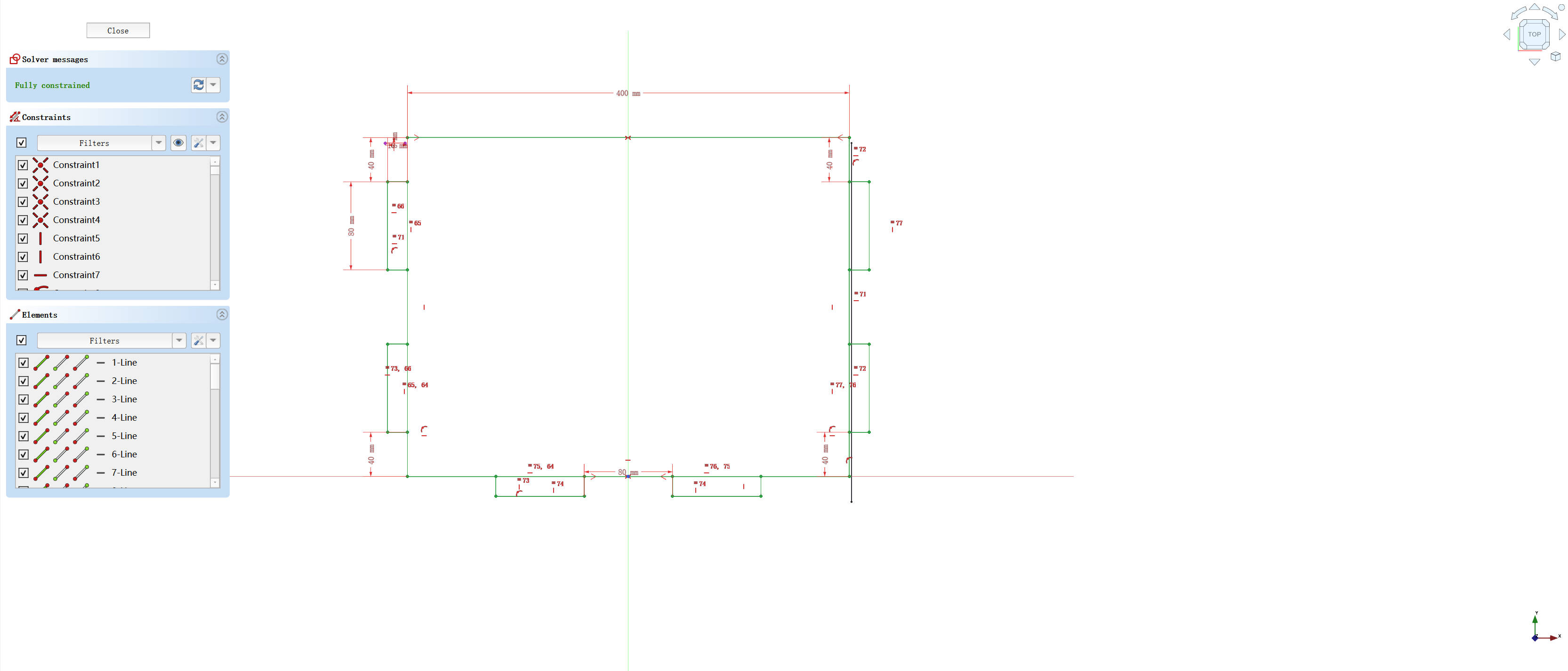
- Each shelf was designed with a primary dimension of 300 × 400 mm, ensuring sufficient storage space.
- Sliding dovetail connections were implemented to facilitate easy assembly without additional fasteners.
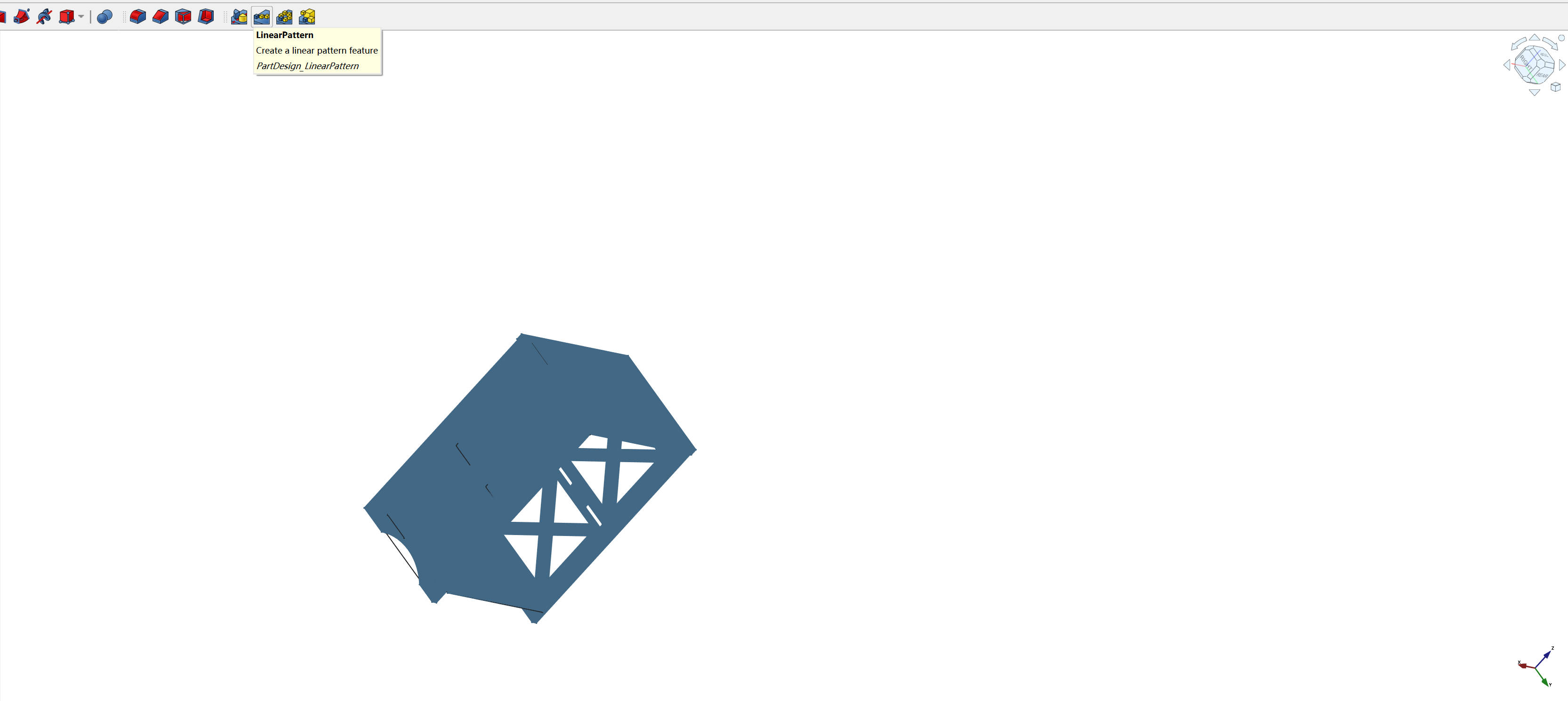
- Model Duplication
- The shelf design was extruded to 18 mm thickness.
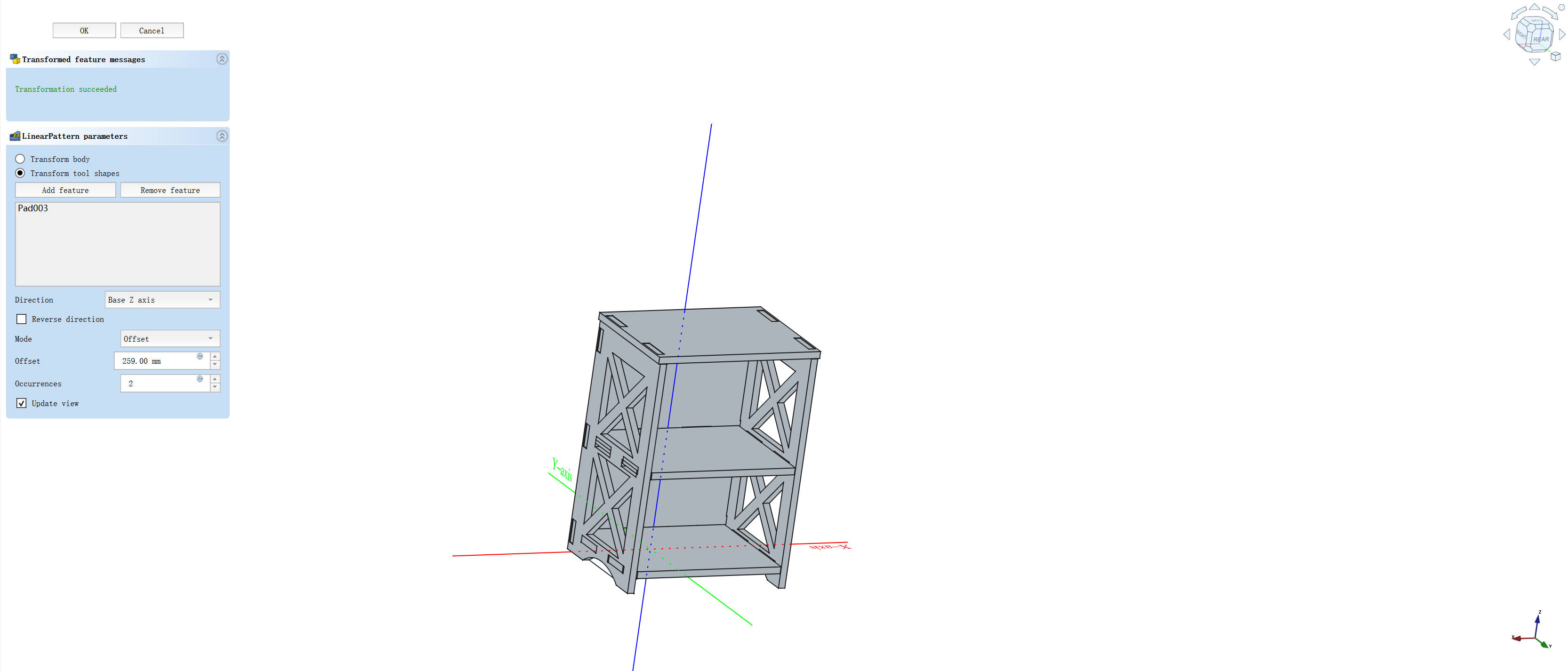
- Multiple instances were created using the Linear Pattern tool for uniform spacing and alignment.
1.2.6 File Export
- The final assembly was converted into technical drawings using the TechDraw workbench for reference and validation.
- 2D profiles were exported in DXF format (R12/LT98) to ensure compatibility with CNC machining software.
1.3 CNC Machining Process
After finalizing the design, the CNC machining process was initiated to transform the digital model into a physical product.
1.3.1 Toolpath Generation
- The DXF files were imported into CAM software (MasterCAM) for toolpath planning.
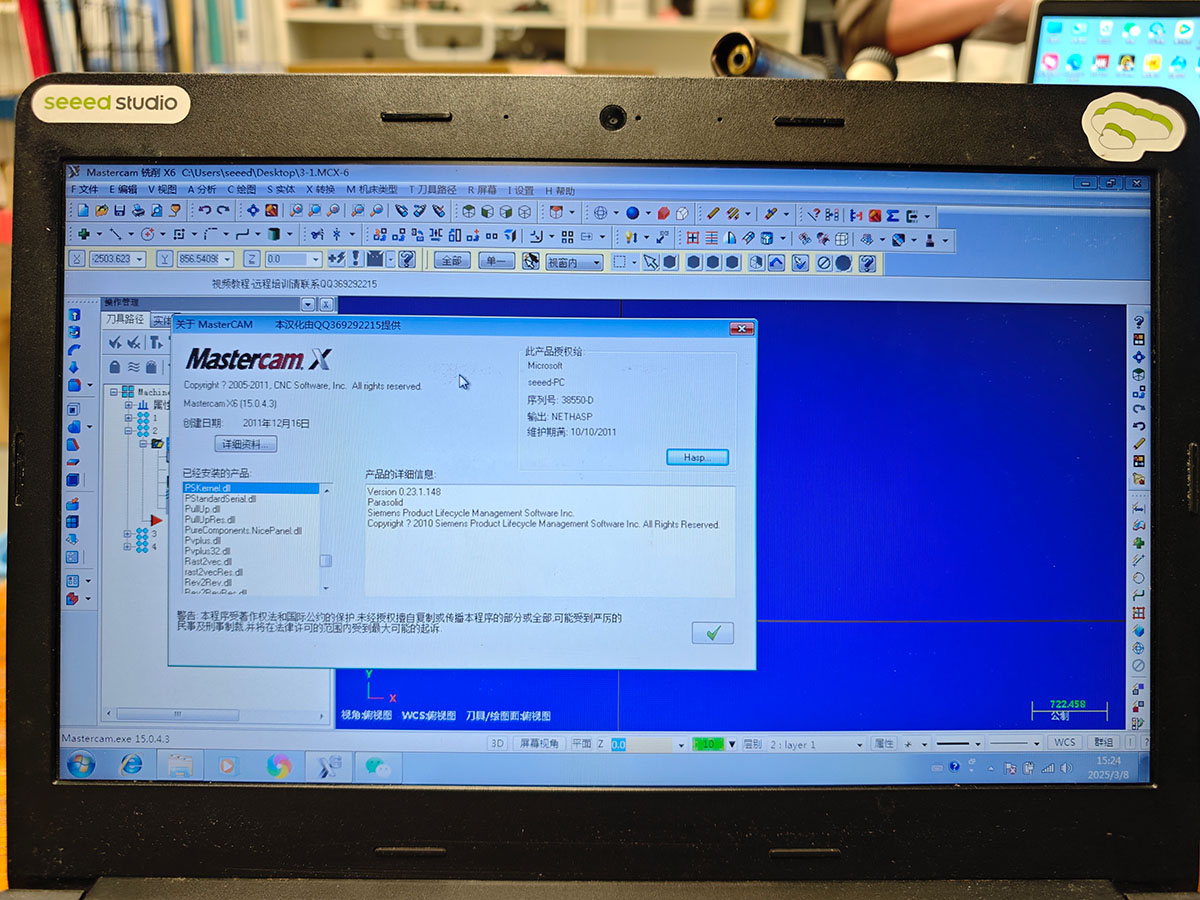
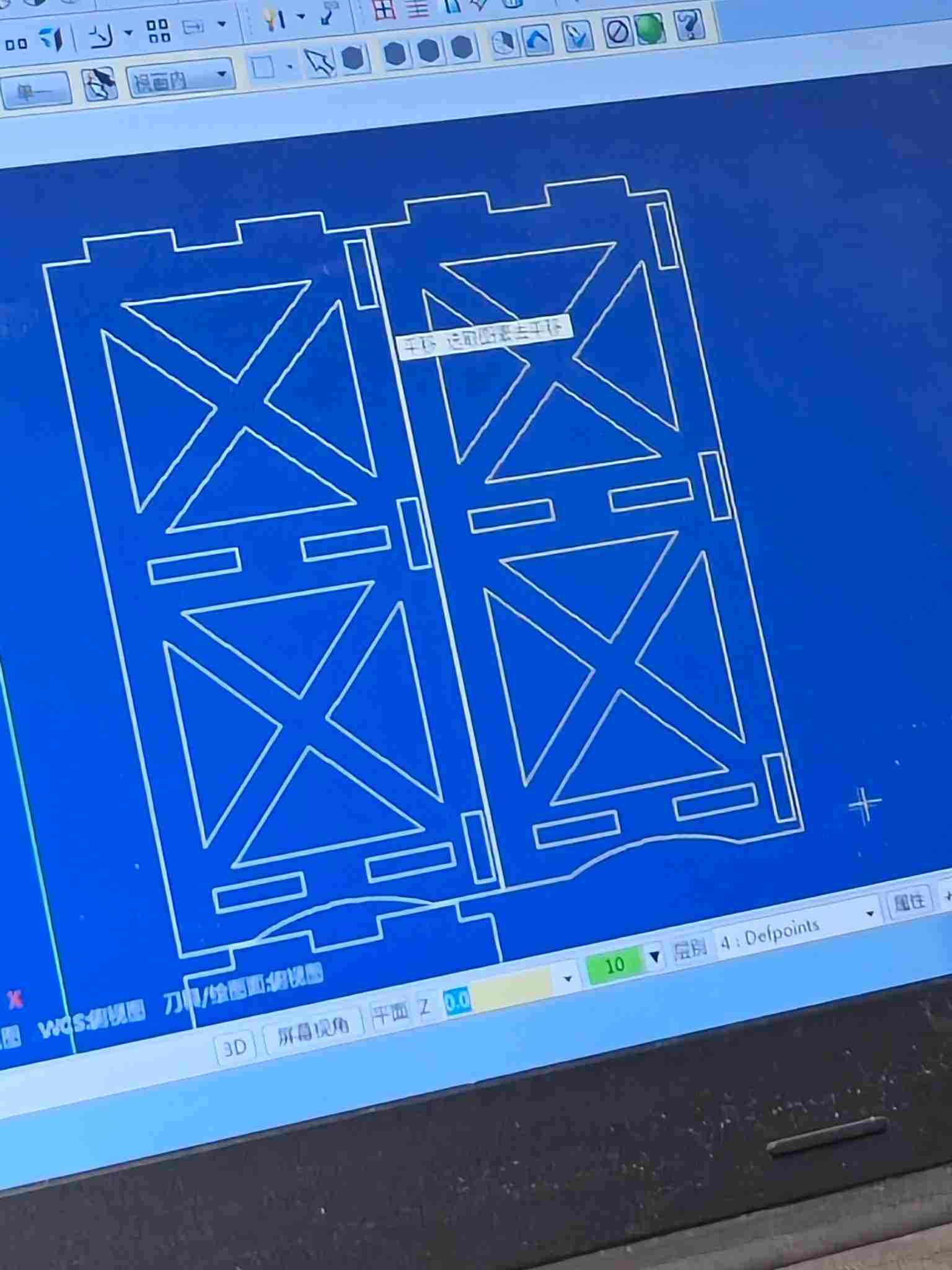
- Cutting parameters were carefully configured to ensure optimal machining performance:
- Spindle direction: Clockwise.
- Feed rate: 5000 mm/min.
- Spindle speed: 15000 rpm.
- Cutting speed: 500 mm/min.
- FPT: 0.0833.
- CS: 377.0028.
- Path Planning:
- 2D contour milling was selected for precision cutting.
- Tool correction was applied to the right, with the calibration position set to the tool tip.
- The maximum processing depth was adjusted to 0.05 mm for high accuracy.
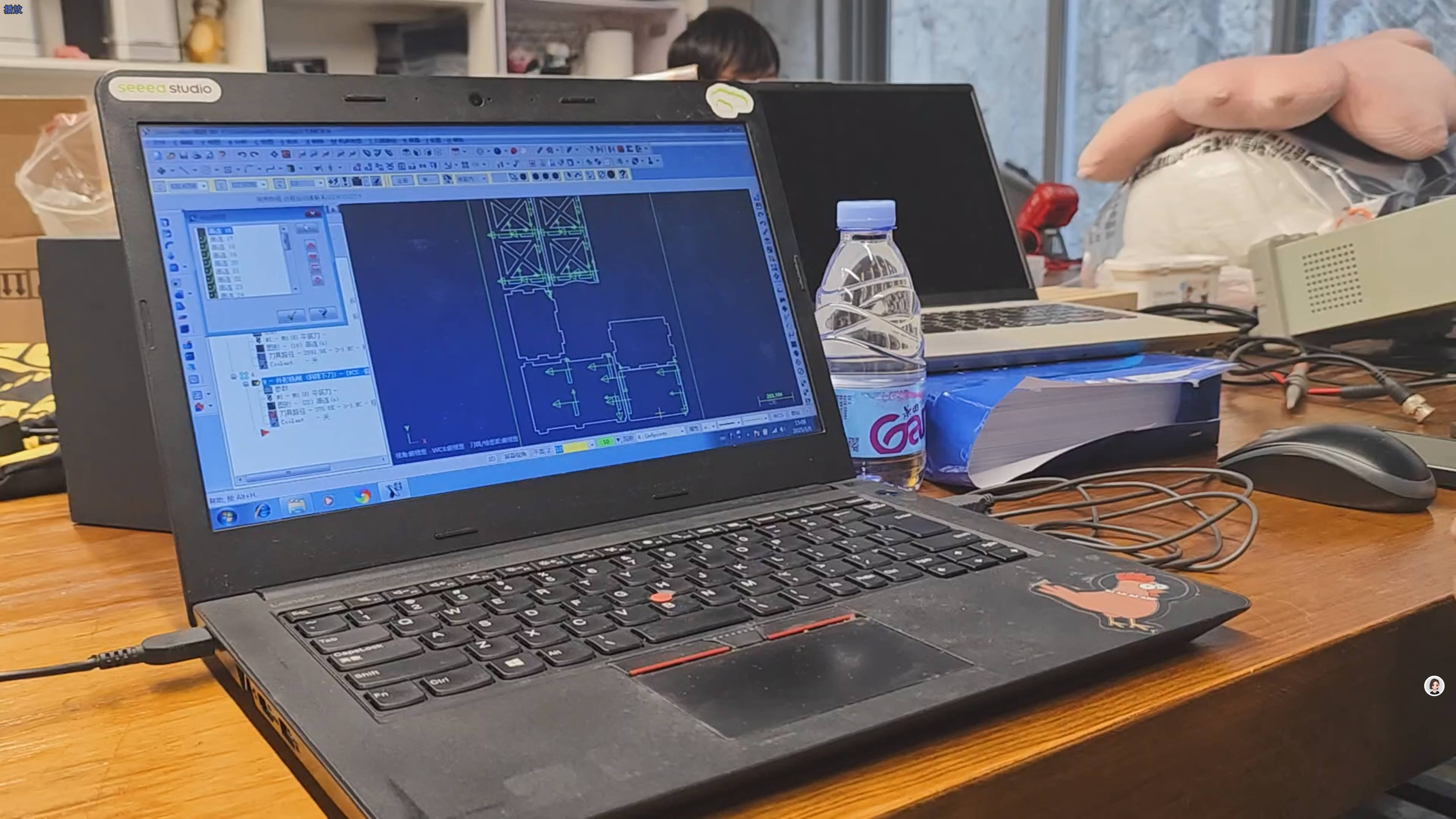
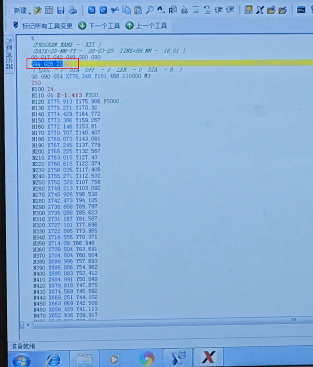
- An optimized G-code file was generated, incorporating a nesting algorithm to maximize material utilization.
1.3.2 Machine Operation
- The plywood sheet (18 mm thick) was securely fixed onto the CNC bed to prevent movement during cutting.
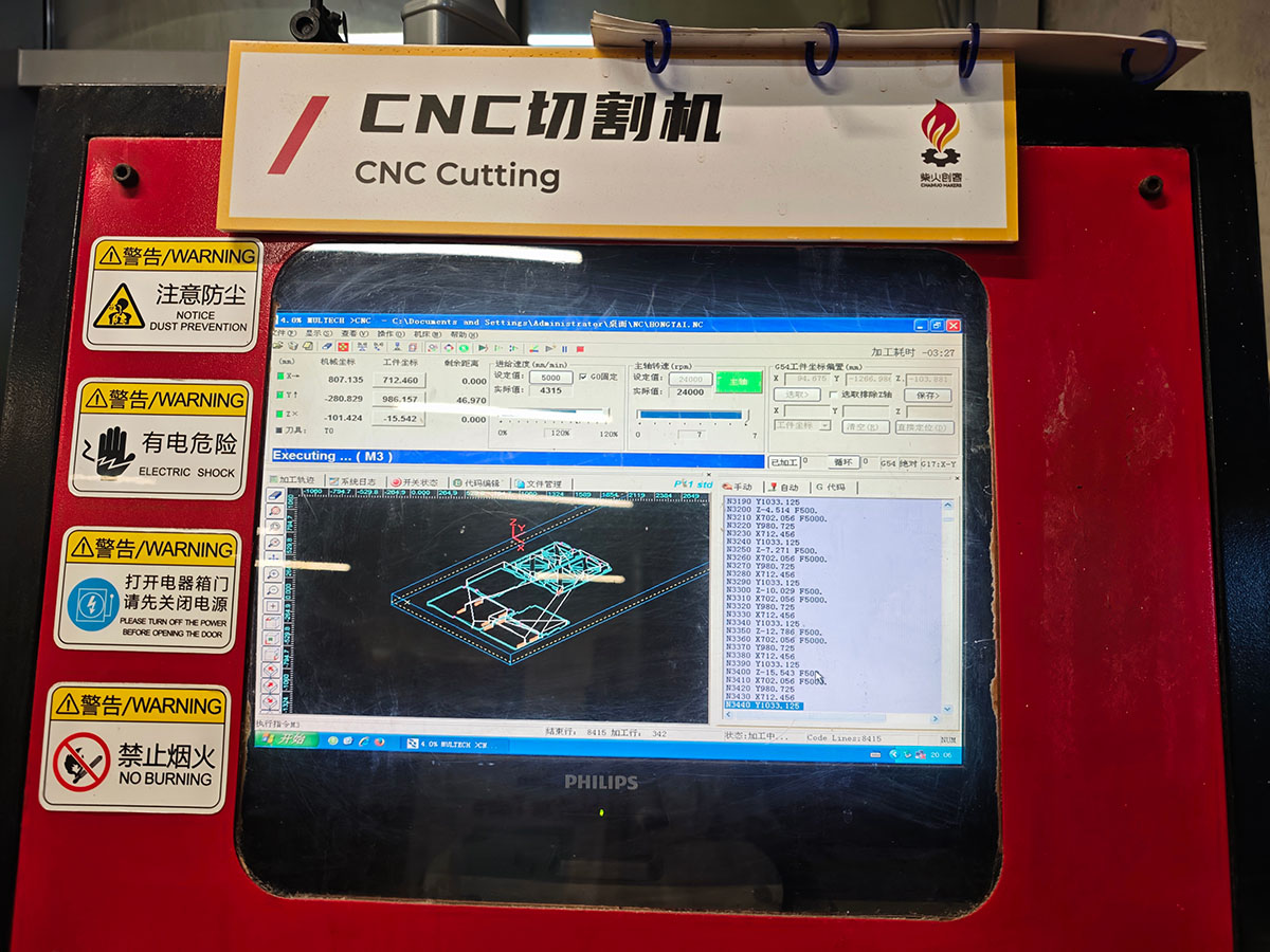
- Tool length probing was performed to ensure precise depth control.
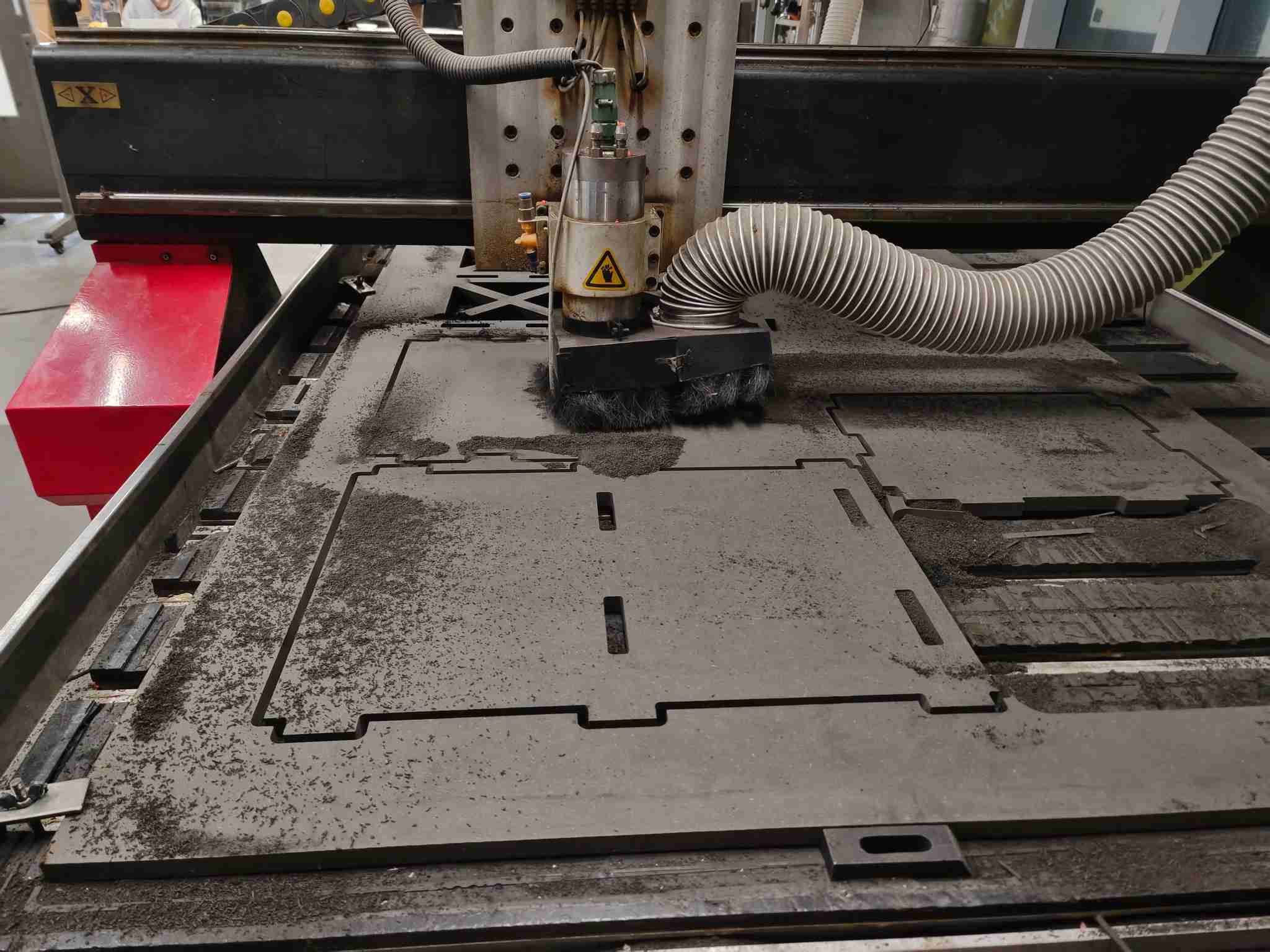
- A dry test run was executed to verify the accuracy of the toolpath before initiating the actual cut.
- The first-off production was closely monitored to ensure quality and consistency.
1.4 Assembly & Validation
1.4.1 Component Integration
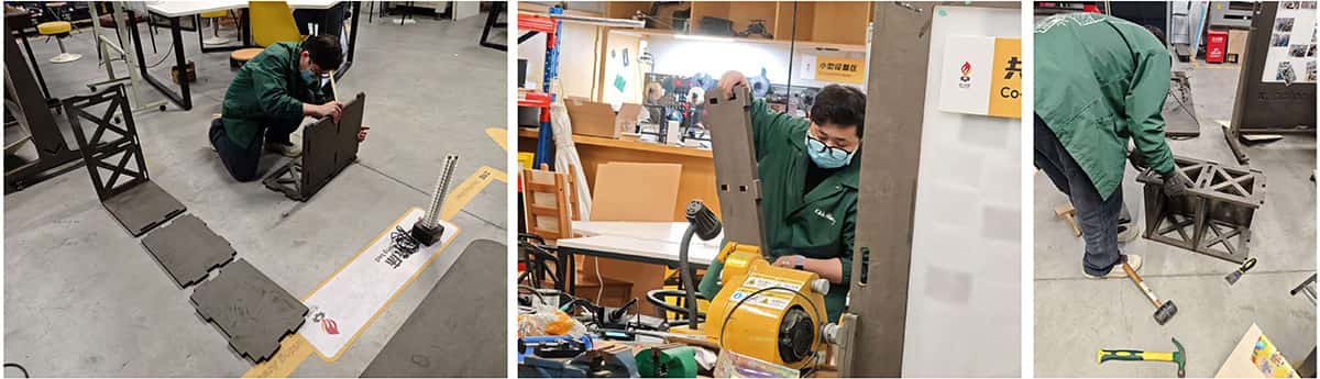
- All machined parts were dry-fitted to confirm proper alignment and tolerances.
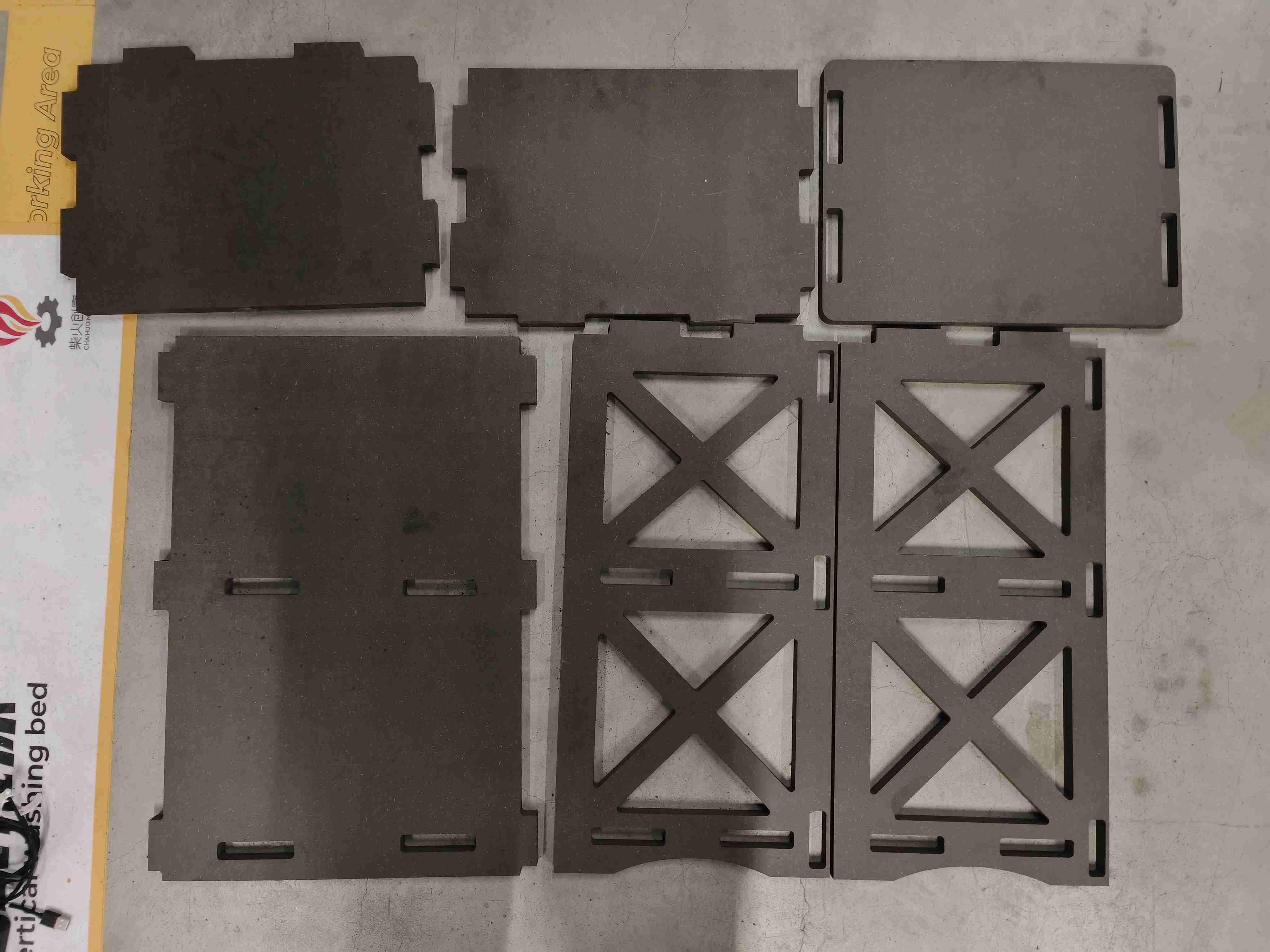
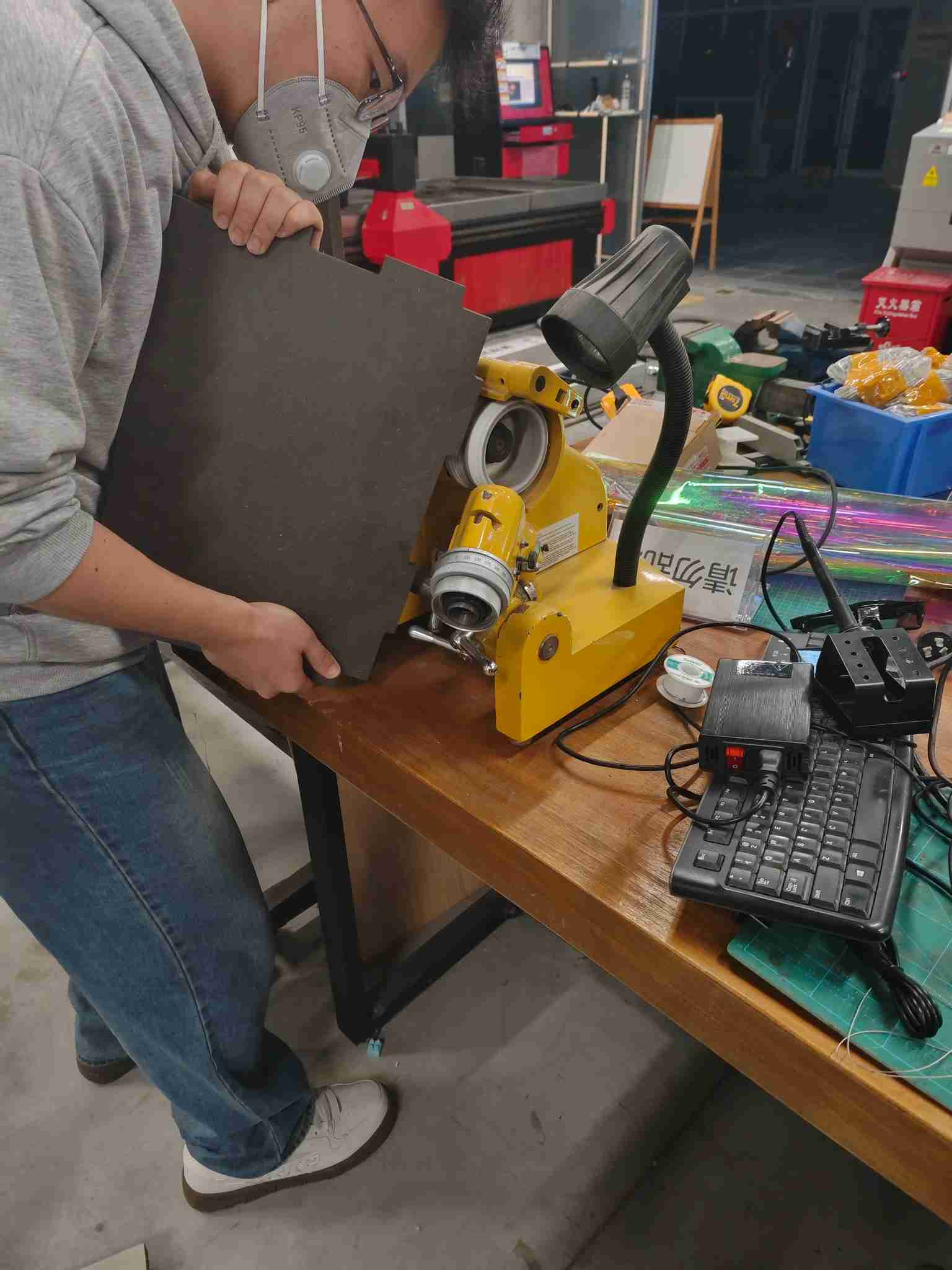
- Manual Chamfering: Some adjustments were necessary due to minor tolerance issues, requiring manual chamfering for smooth assembly.
1.4.2 Final Validation
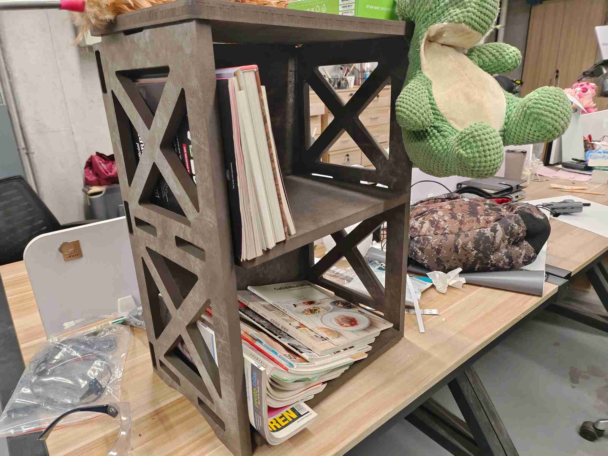
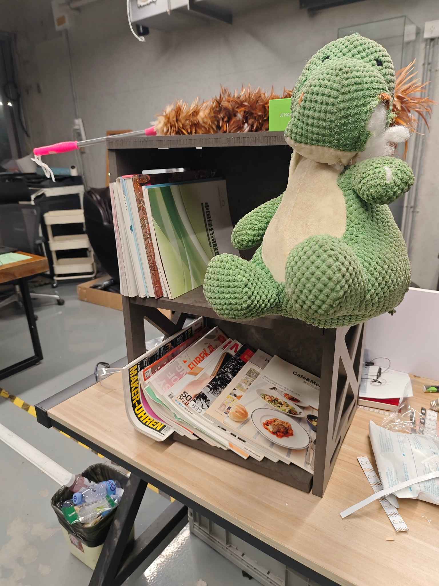
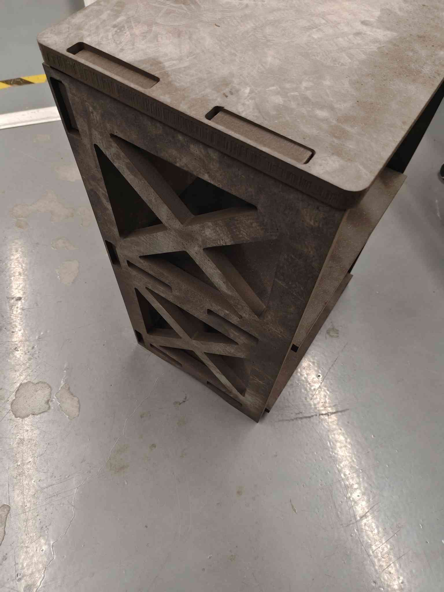
- After a final inspection and validation, the bookshelf was assembled and ready for use.