Final Project - Shelter & Feeder Modeling & Manufacutring
File Sharing
Costs of Materials
| Item | Function | Price | Count | Link |
|---|---|---|---|---|
| HDF board (1m*1m) | Car shelter making | 30 | 1 | link |
| eSUN PLA+ | Auto-Feeder Printing | 25.99 | 1 | link |
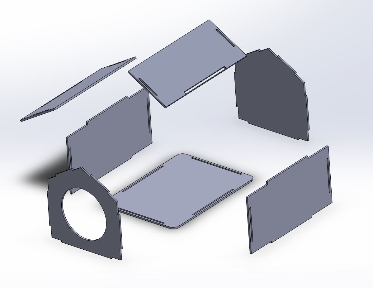
Cat Shelter Version 1: Modeling the cat shelter in cause of 3mm wood board.
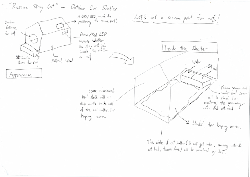
According the design sketch which is shown above, I need to separate the cat shelter to pieces of parts.
Here's the 3D model of the cat shelter model.
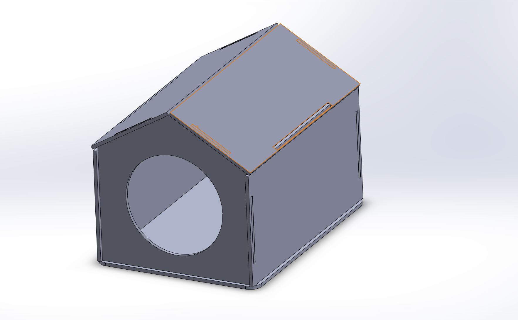
This design by designed fixing by simple mortise & tenon, which thickness of material is 3mm.
In my planning, the shelter will be divided to plate parts. I need to confirm the size of a cat and then some size can be confirmed.
So I setup the sizes as variables and draw a design sketch as below. I choose laser cutter to layout the parts of shleter. The layout process can refer by here.
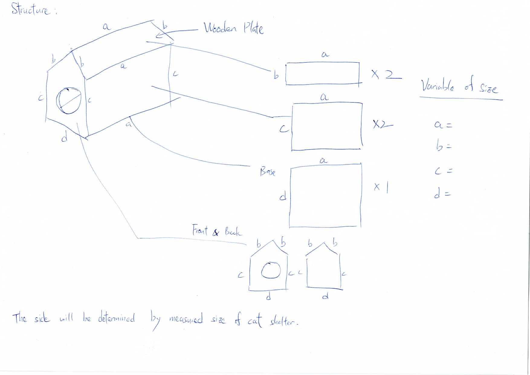
By the way, this structure can be made by laser cutter which allows manufacturing with thin plates, but it's not robustness.
In order to ensure the robustness of designed cat shelter, a thick material is needed. 18mm thickness of wood board is considered in the next design.
Cat Shelter Version2: Modeling cat shelter in cause of 18mm HDF board.
The design step can refer to Week7 Assignment
Design
I have designed a type of cat shelter during designing the final project with the 3mm wood plate.
It can not afford a 8kg cat. Then I find the other material and type of cat shelter.
Considering the designed cat shelter is used for stray cats, it means the cat shelter which will be placed outdoor environment. So I also consider about the cat shelter can also as a artwork.
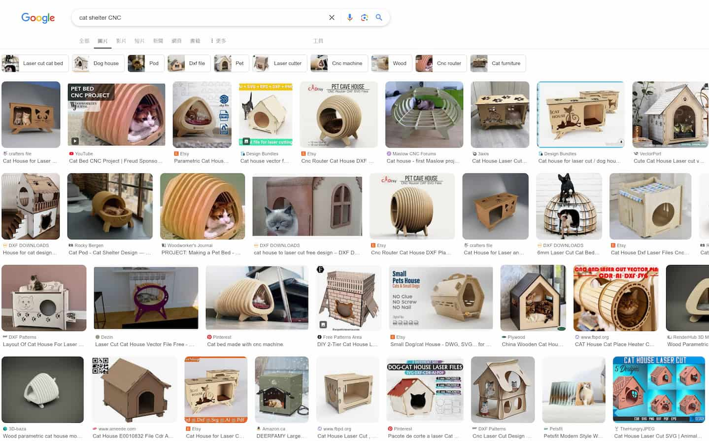
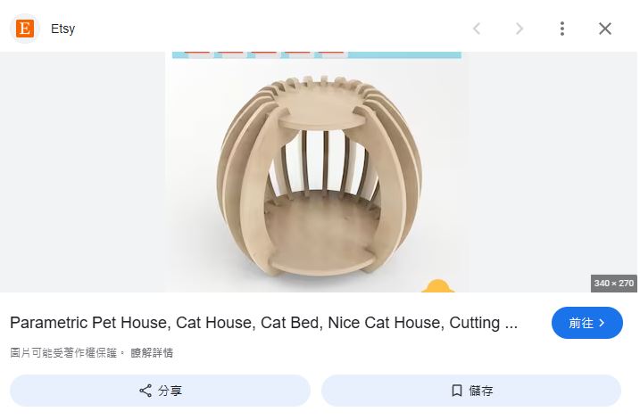
I found a type of cat shelter in etsy.com and looking for the shelter as below. And I found the vector files sample of this cat shelter.
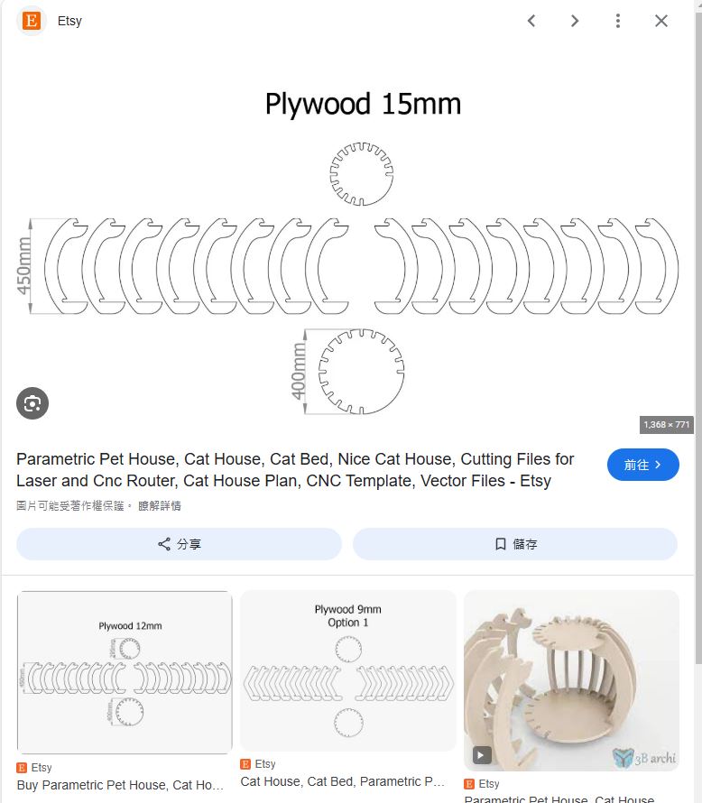
Then, I start designing this cat shelter by 3D software - Solidworks.
As it is a assembled project, I will design the 3D model by top-down designing.
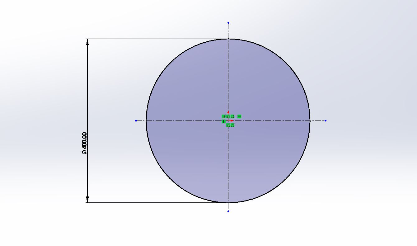
Base Part
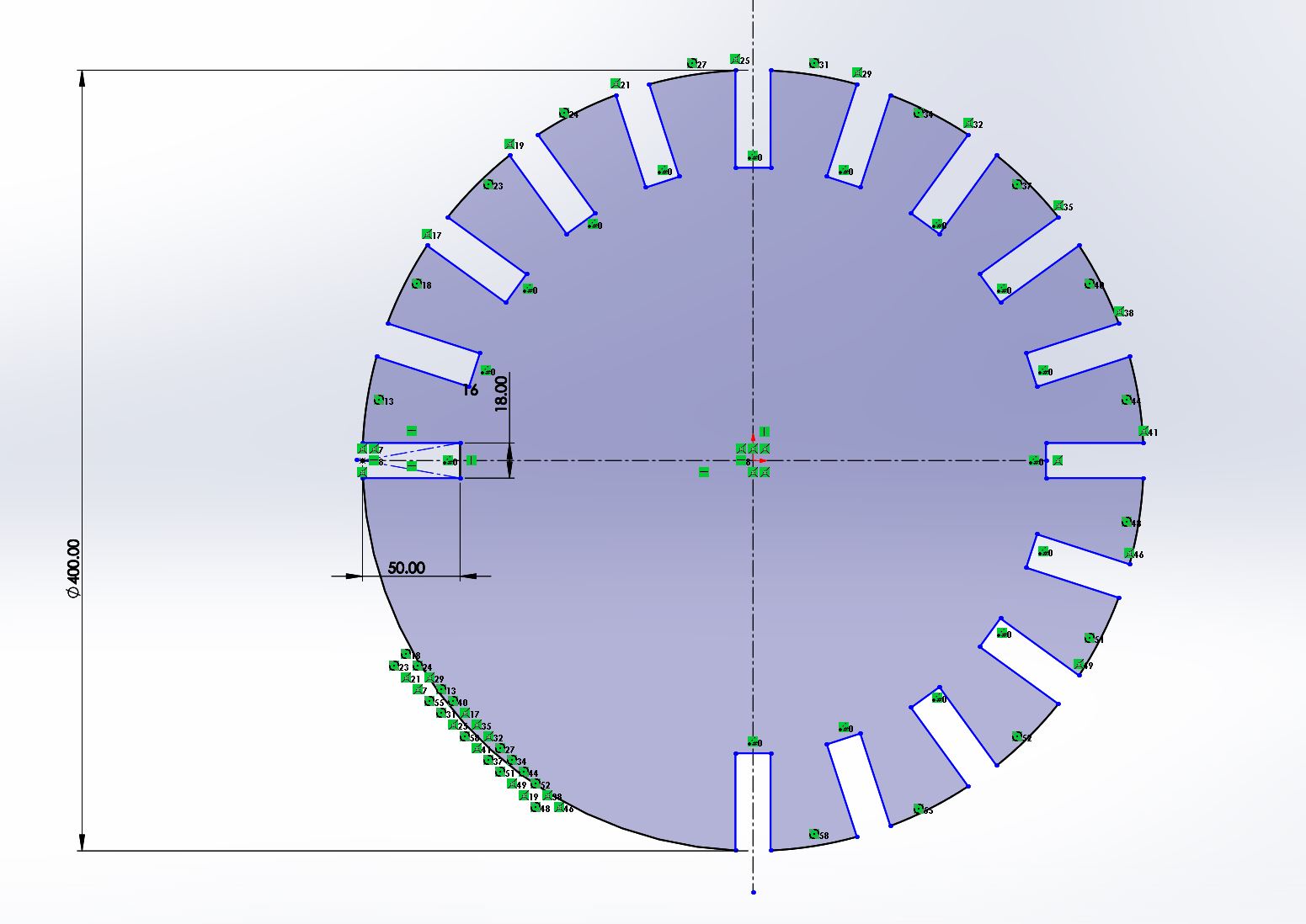
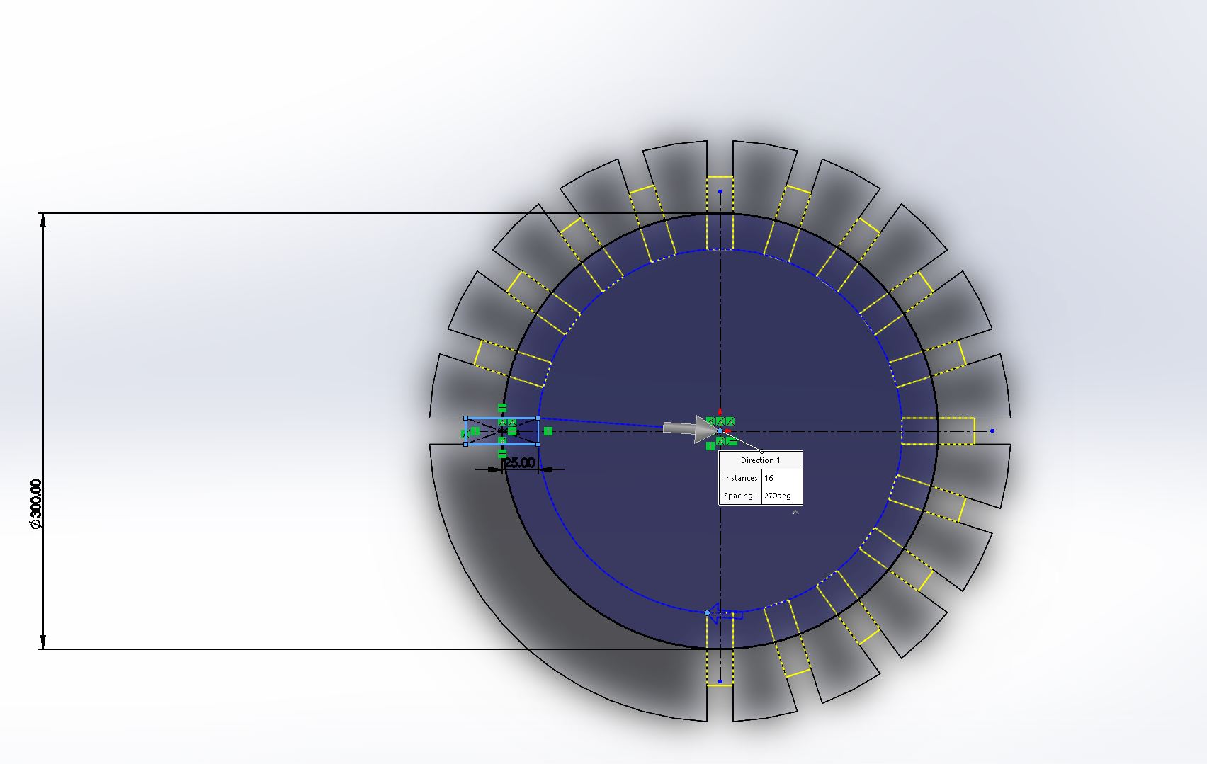
The base design is started from a diameter 400mm circle.
Then, draw a 100mm*18mm rectangle as below.
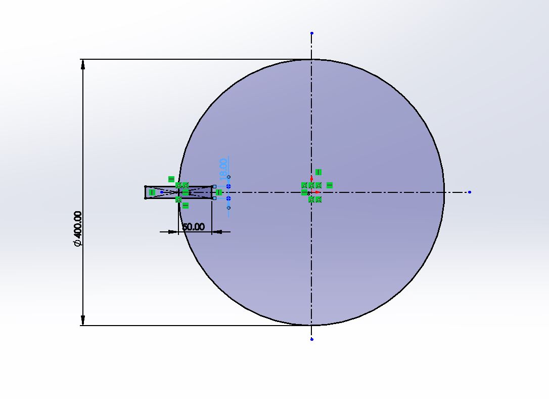
Use Circular sketch pattern tool to copy 16 rectangles in circle 270 degrees.
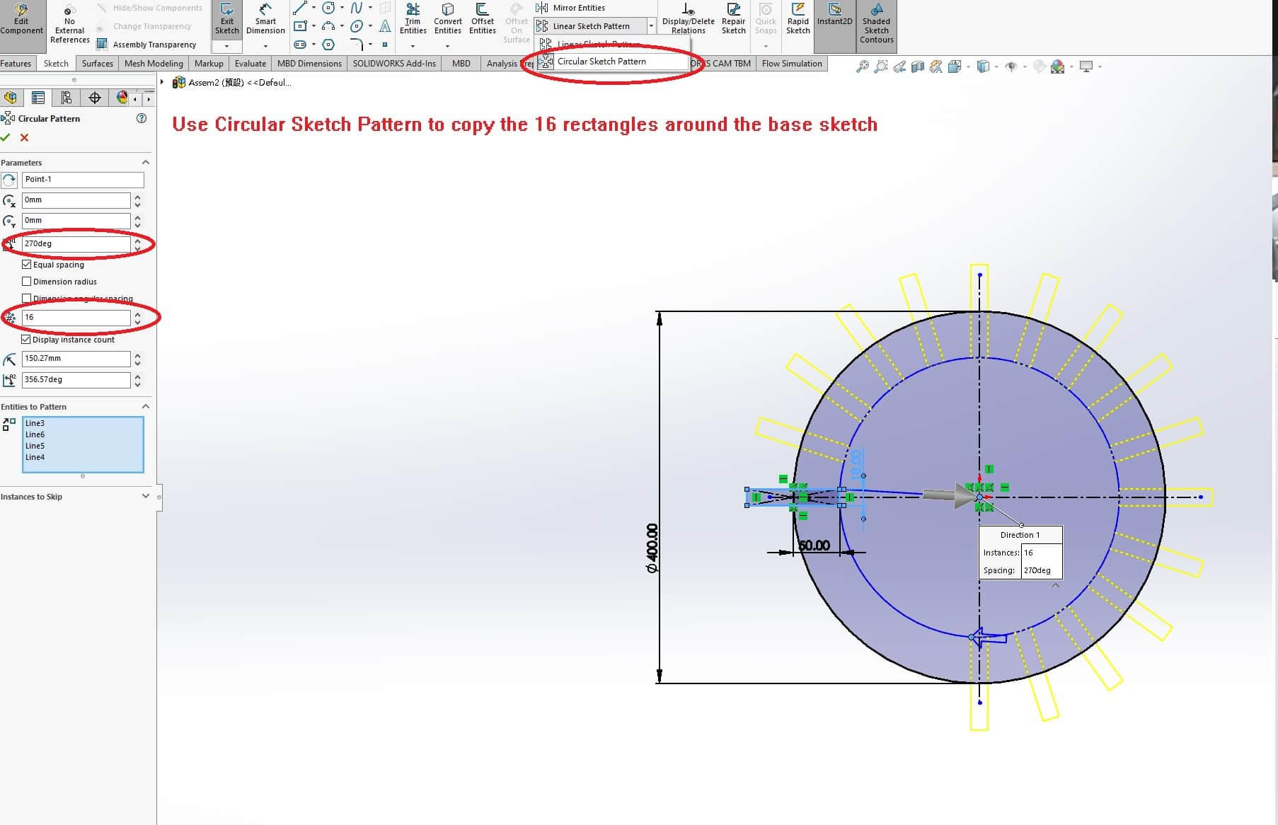
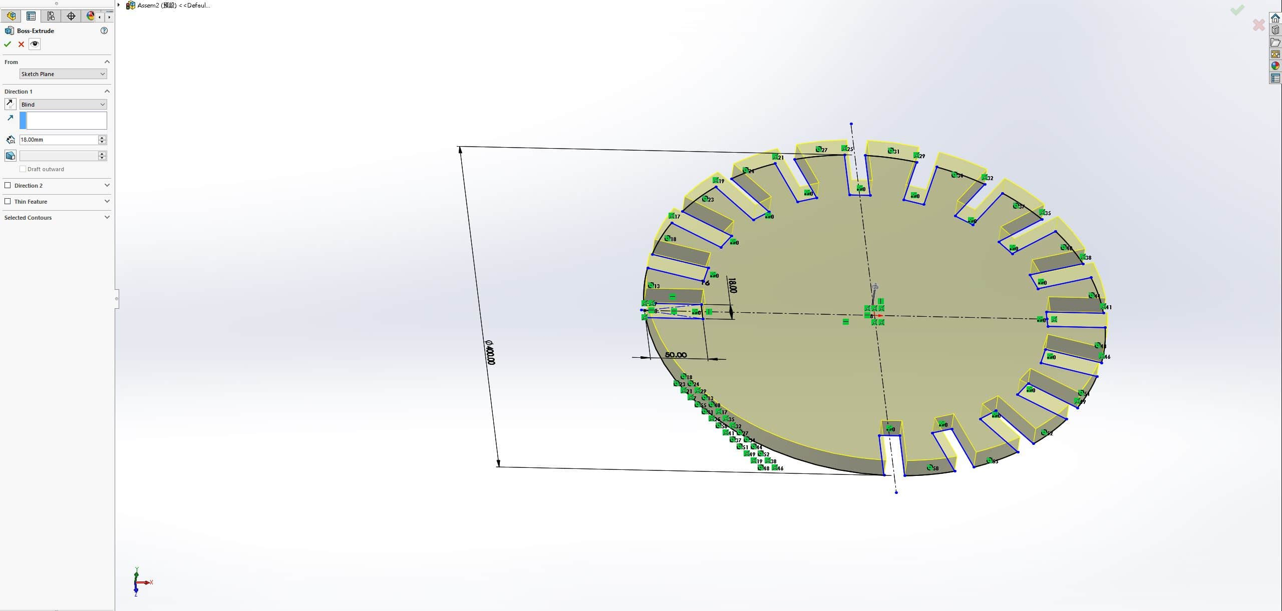
Use Trim tool to remove the sketch lines and extrude the sketch as 18mm, which is the thickness of our cutting material.
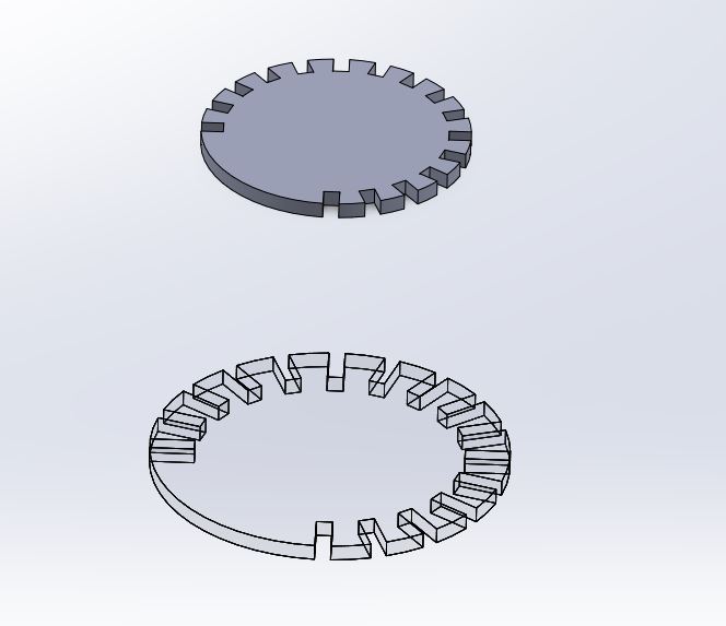
Top Part
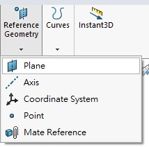
Use Plane tool in Reference Geometry to create a plane base on 400mm above the surface of base part.
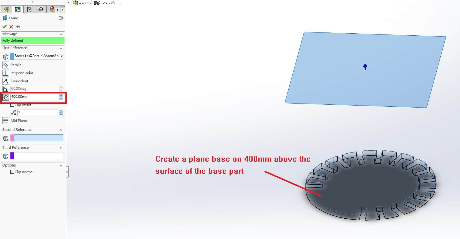
Then, repeat the step as drawing the sketch of base part with 300mm diameter circle and 50mm * 18mm rectangle. Extrude the sketch with 18mm thickness.
Side Part
Choose Front view and draw a new sketch as below.
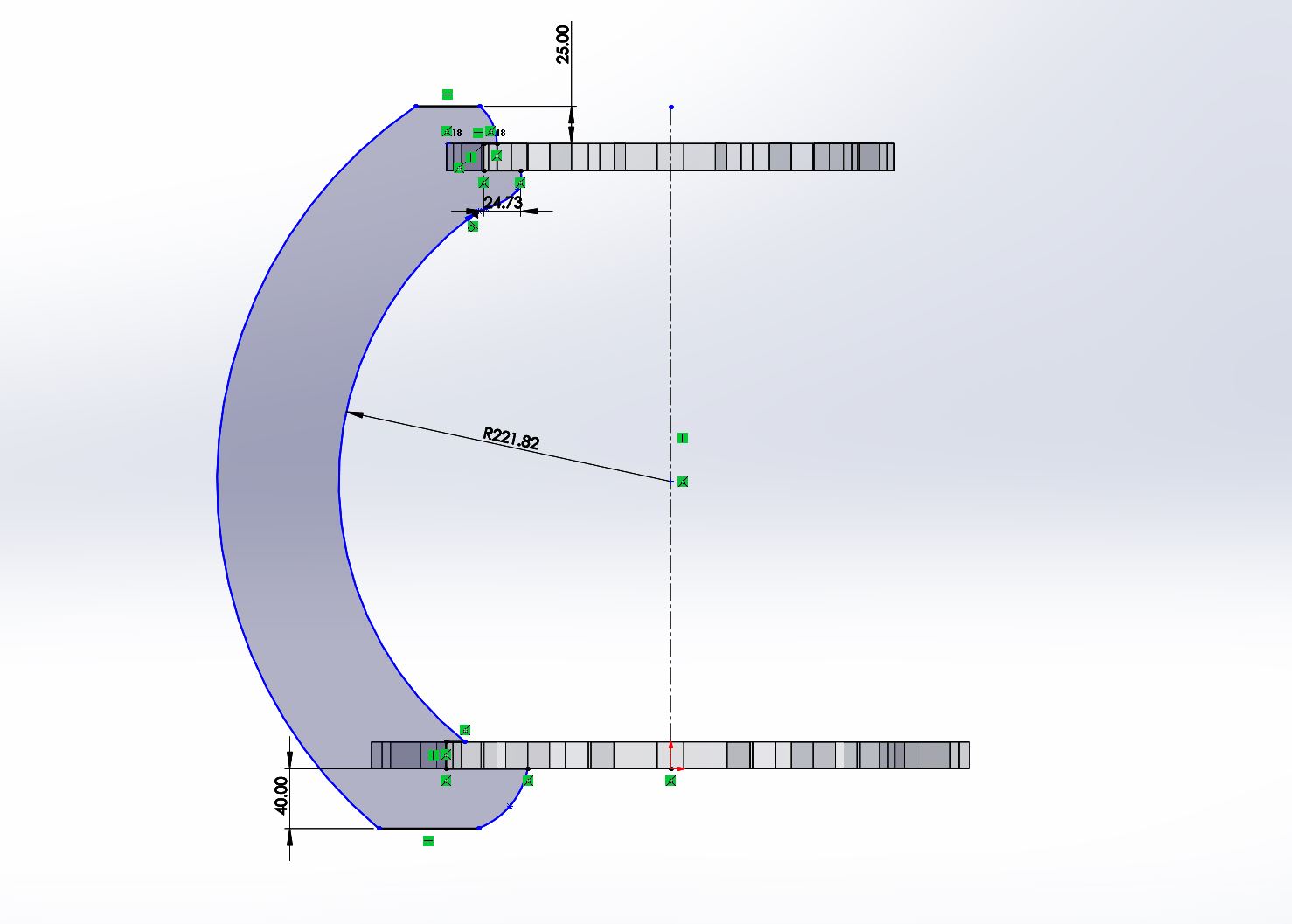
It is the supporting parts between base part and top part, a thick design is necessary or it will be broken because of heavy weight.
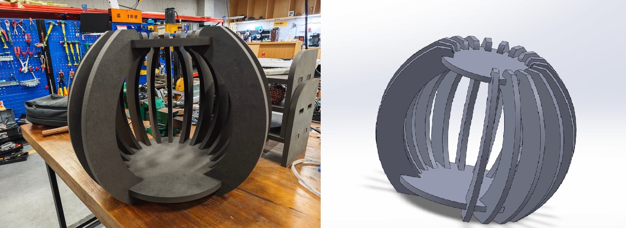
Made up
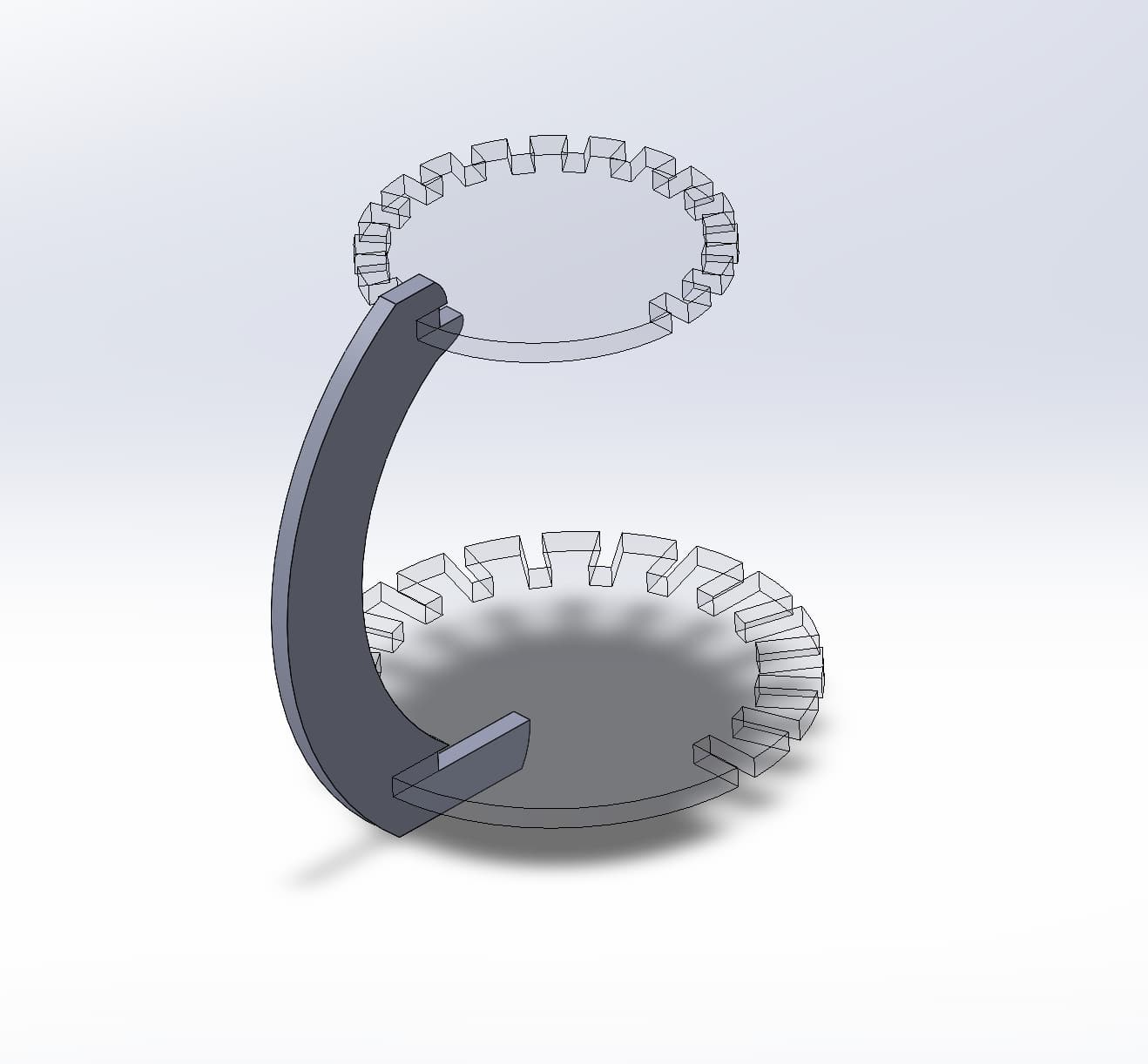
The assembling parts is shown as above, there's only one side part to support. It's not enough to maintain the structure of the shelter.
Finally, I use 16 side parts to maintain the base part and top part.
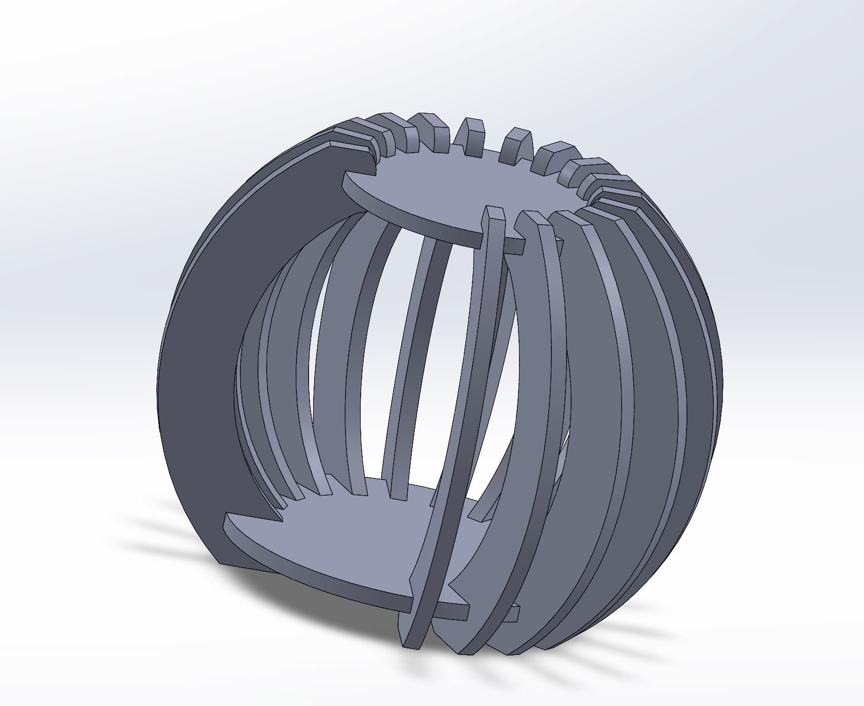
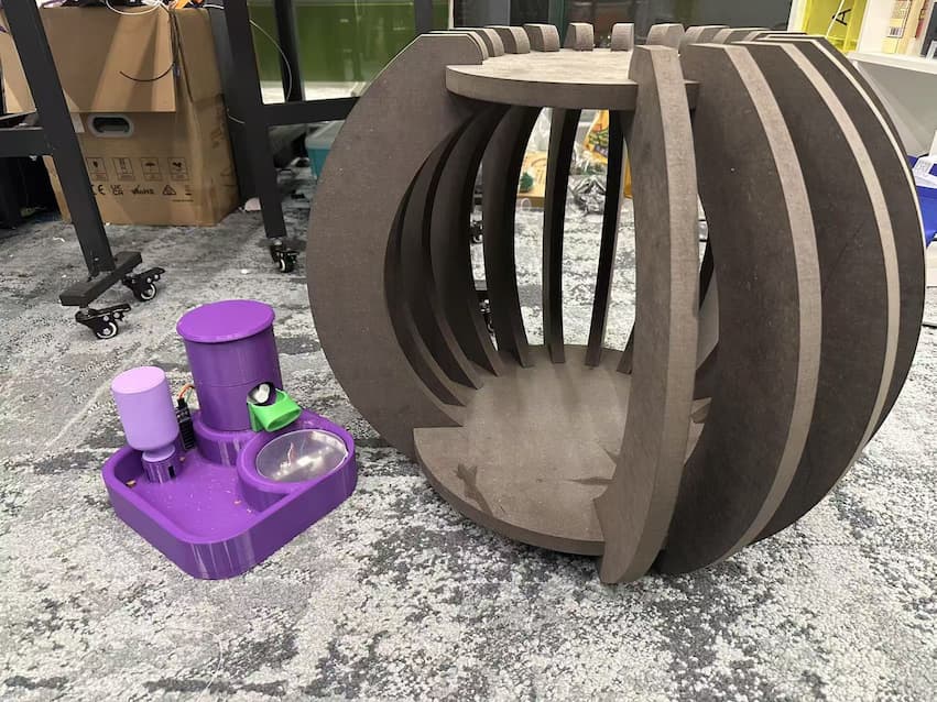
An artwork-designed cat shelter, finished!! This shelter will be used for my final project.
Manufacutring
The process of manufacutring the shelter can refer to Week7 Assignment. CNC manufacutring is substractive manufacutring.
Here's the time slap video.
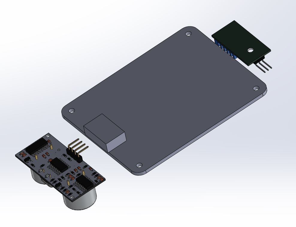
Control box of the Environment Sensing
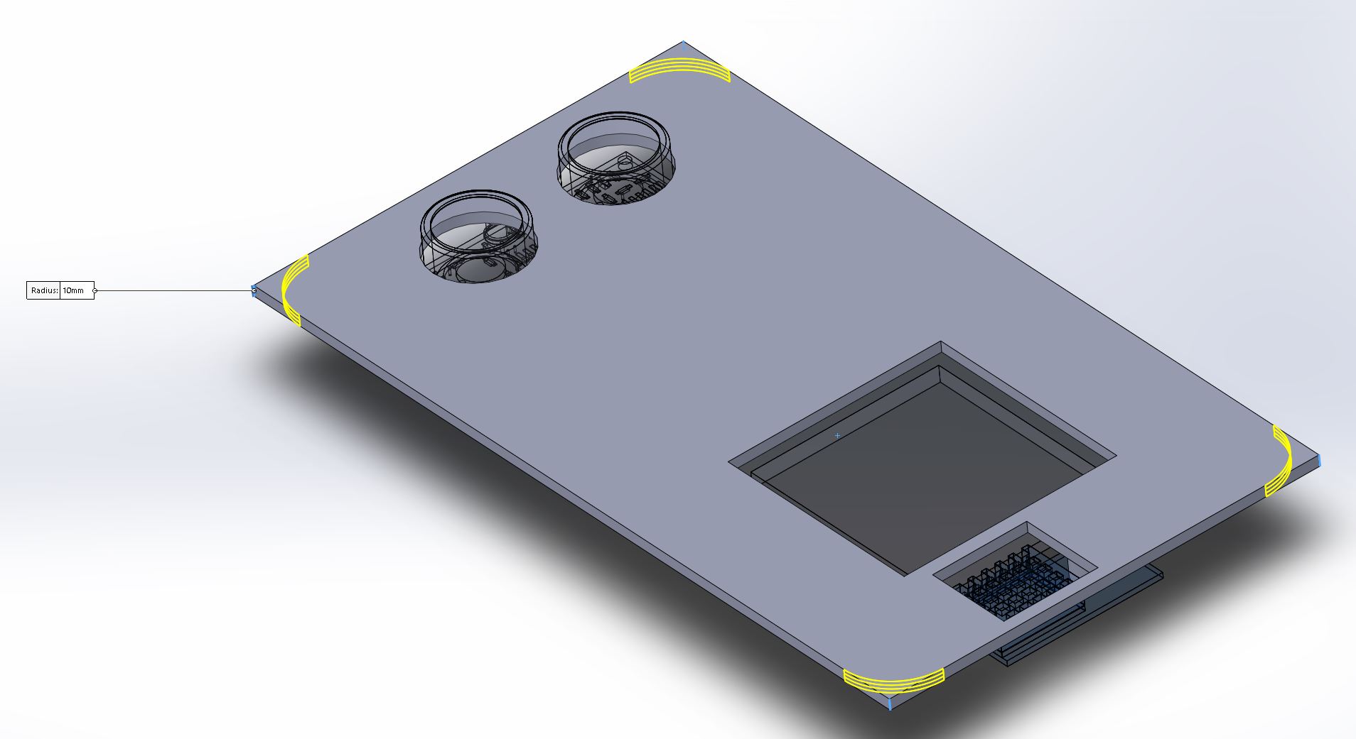
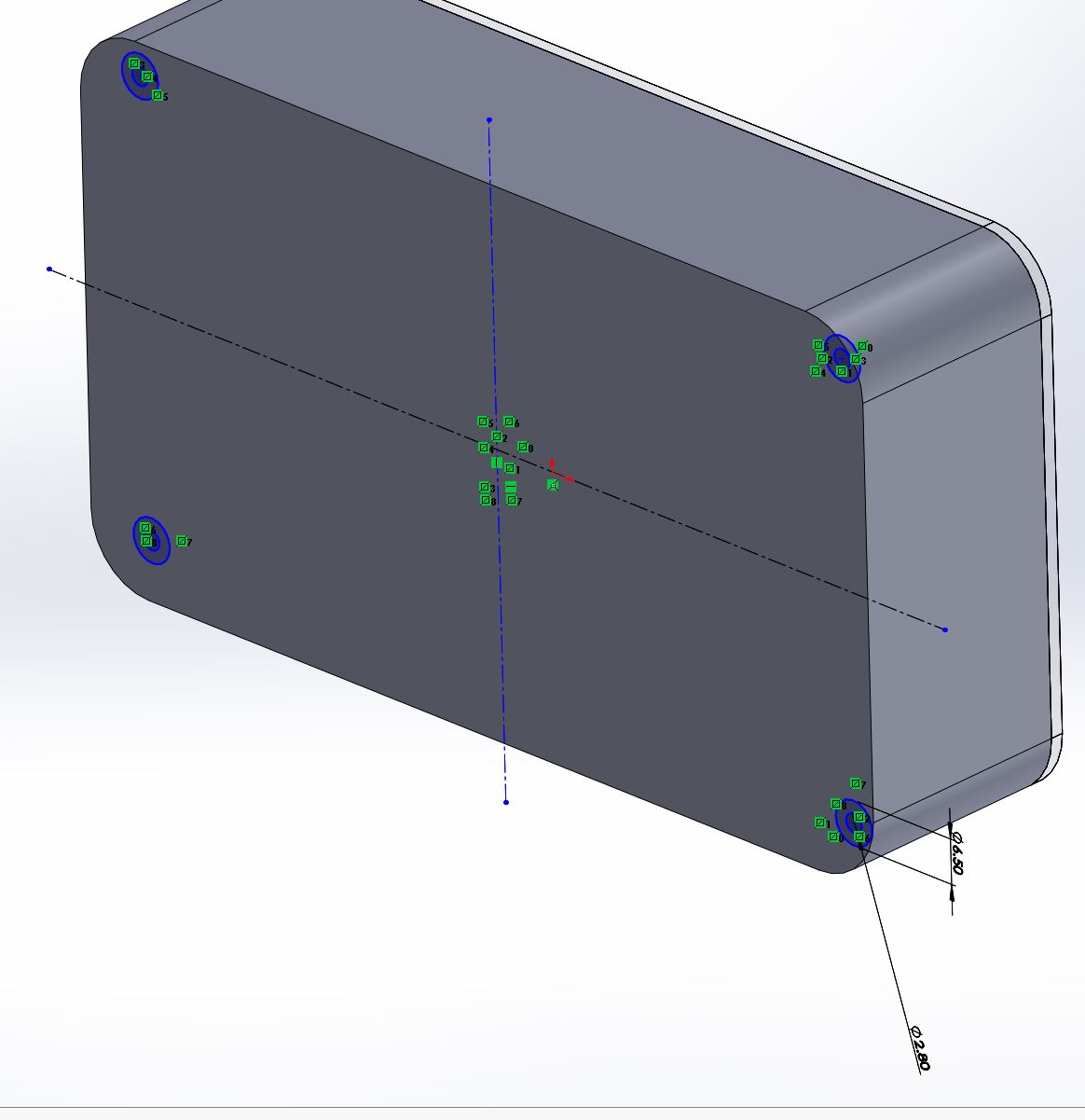
The designed PCB will be inserted into a designed control box. Here's the design in solidworks.
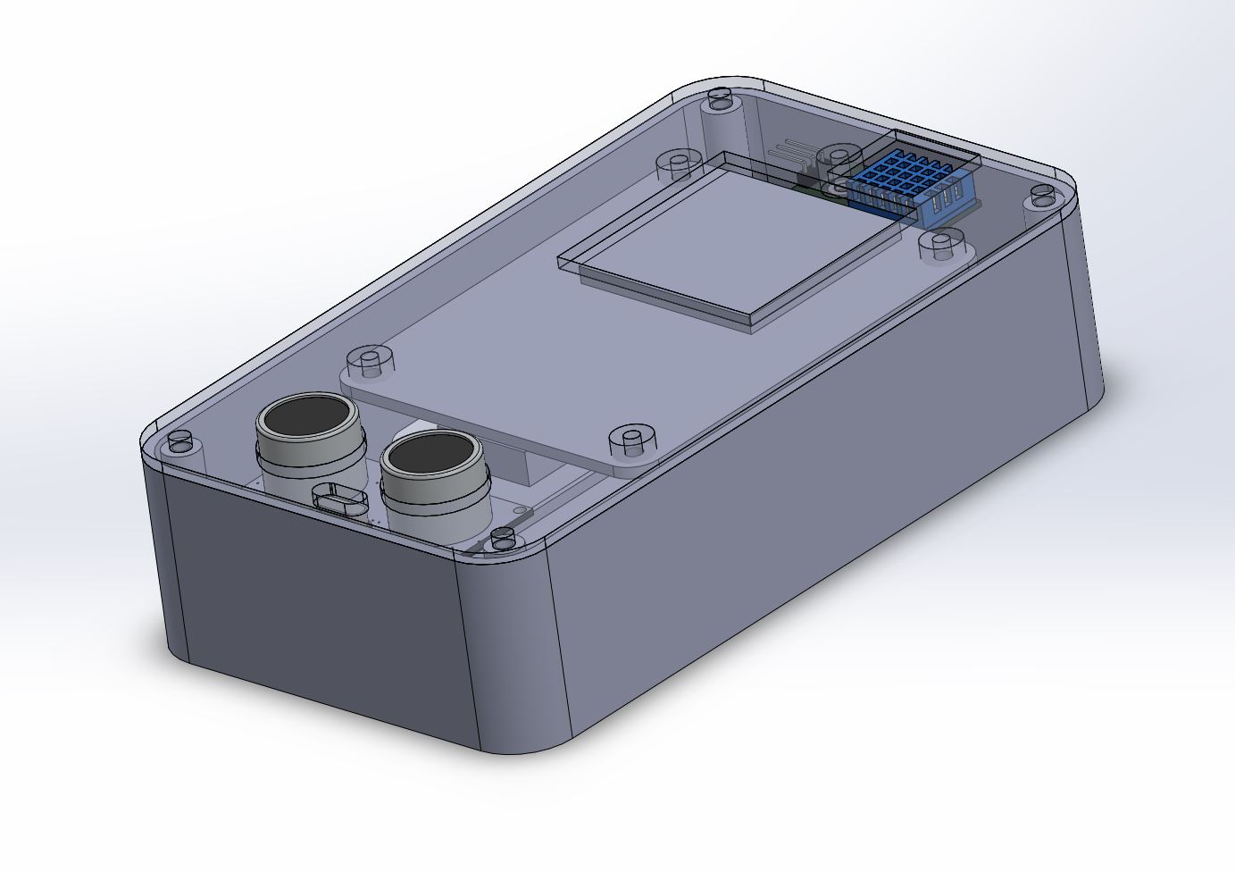
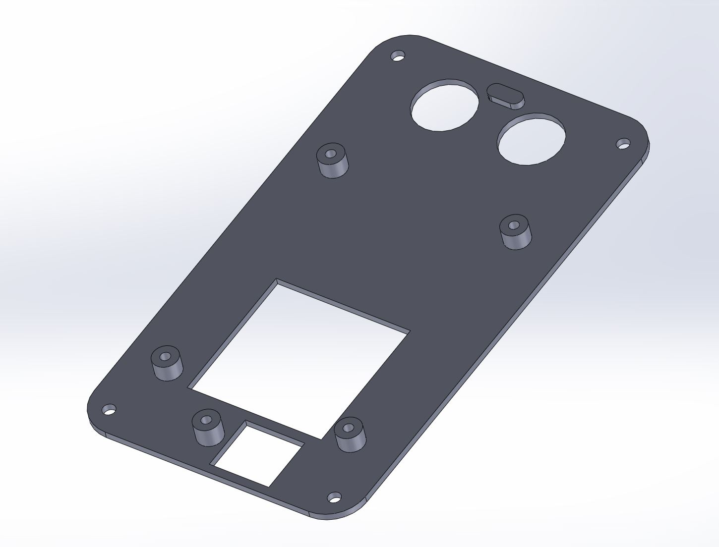
In 3D modleing, 3 sensors will be placed at same plane first.
Draw a 140 * 80mm rectangle and extrude it.
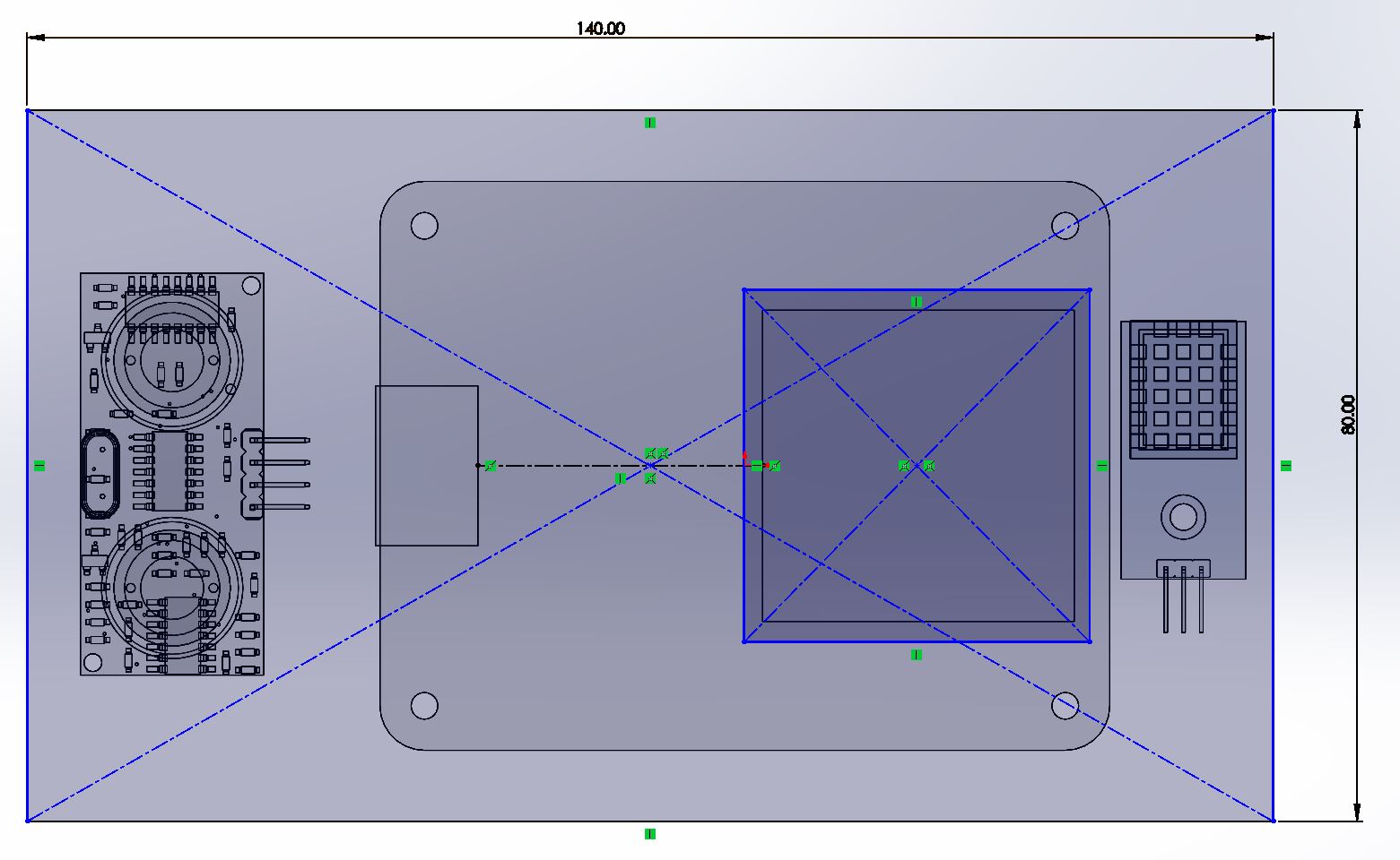
Draw the circles and remove it for placing the ultrasonic sensor.
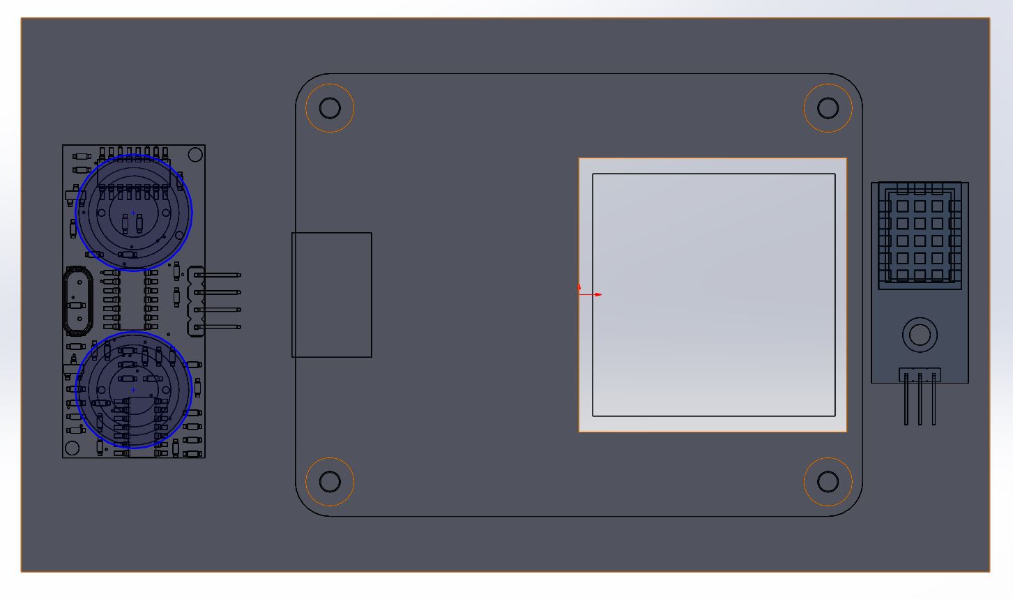
Then, draw the sketch for 4 circles which size is align to the BDS antennia's hole and extrude it.
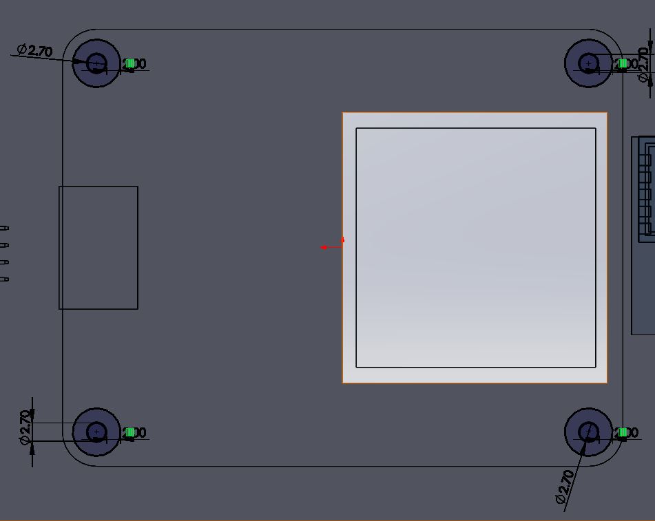
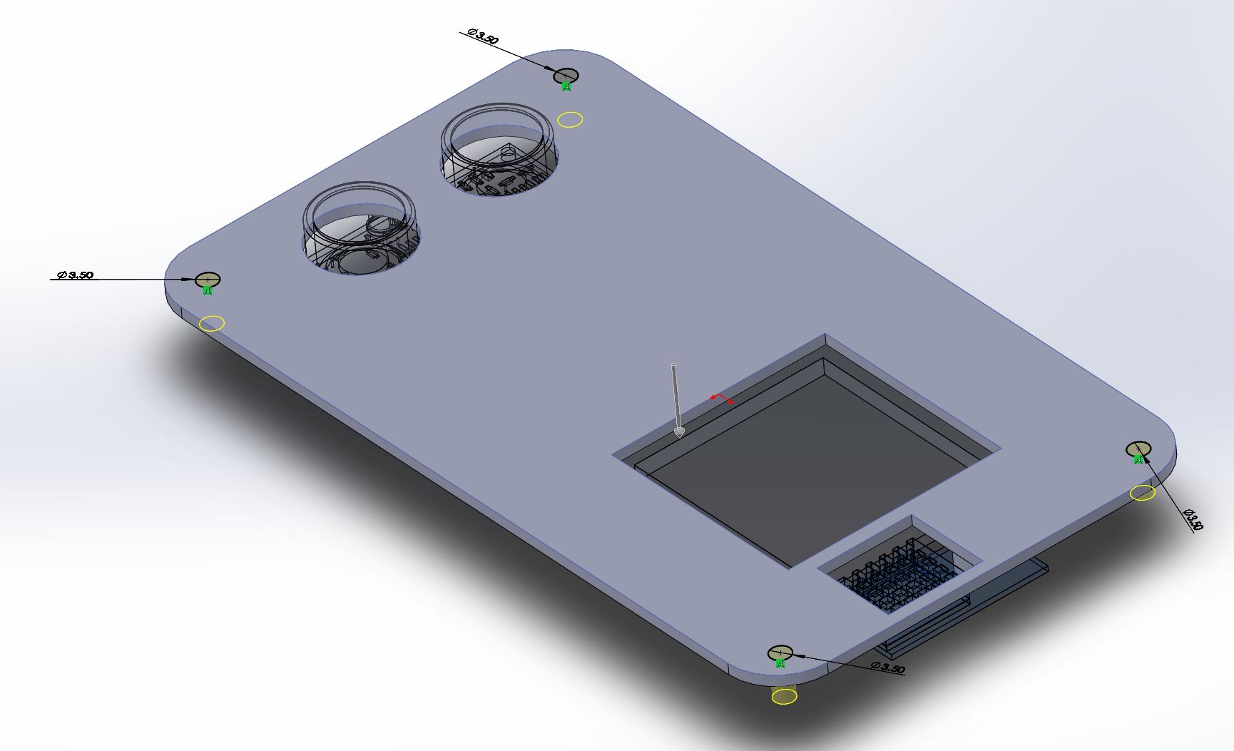
Turn the corner of rectangle to fillet with radius 10mm.
Draw the screw holes for M3 screws and remove it. The top cover is finished!!
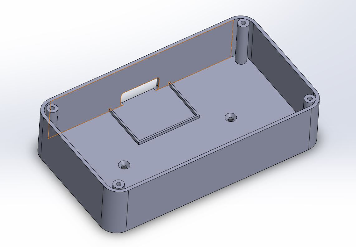
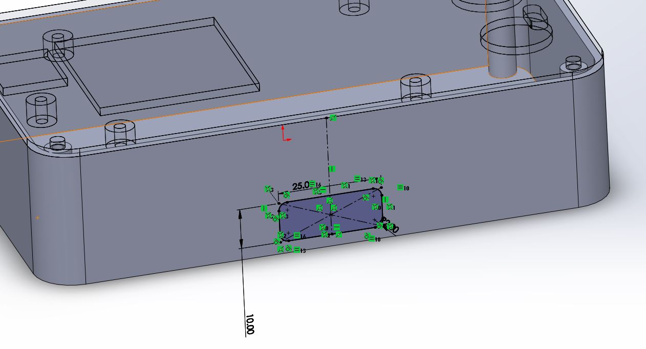
Let's modeling the lower part of the control box. First convert the sketch from the top cover.
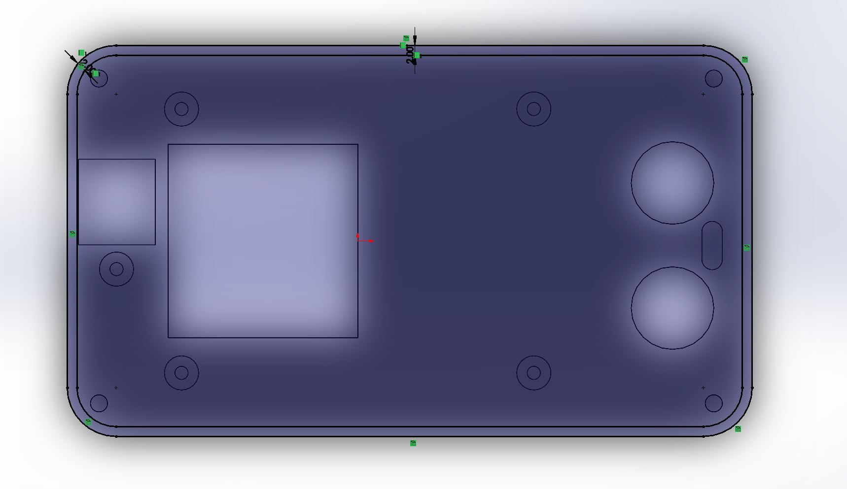
Extrude it.
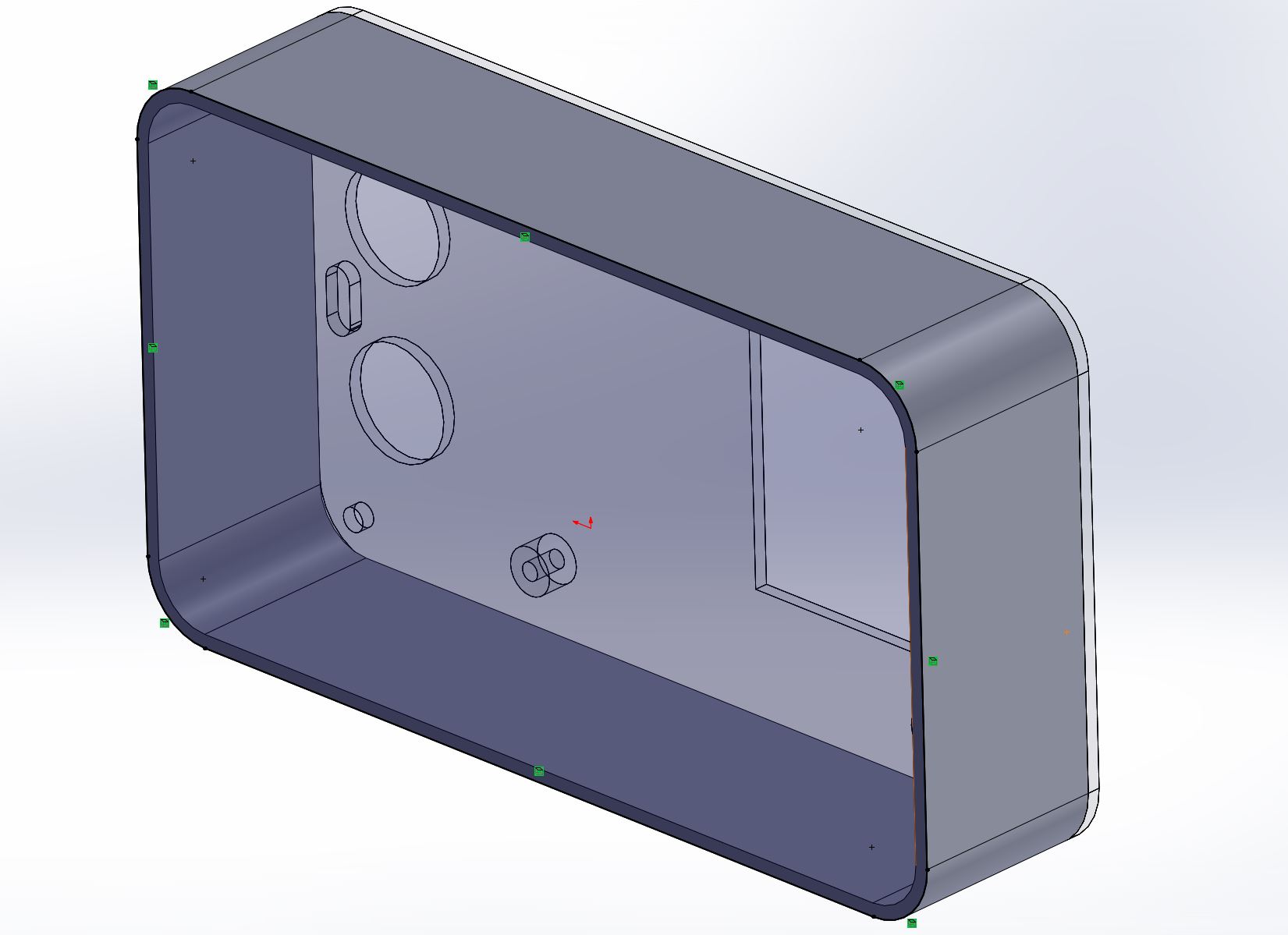
Then, extrude the bottom and draw 4 screw holes for fixing the top cover.
Draw a hole for plugging the USB cable for PCB board. The box part of the control box is completed.
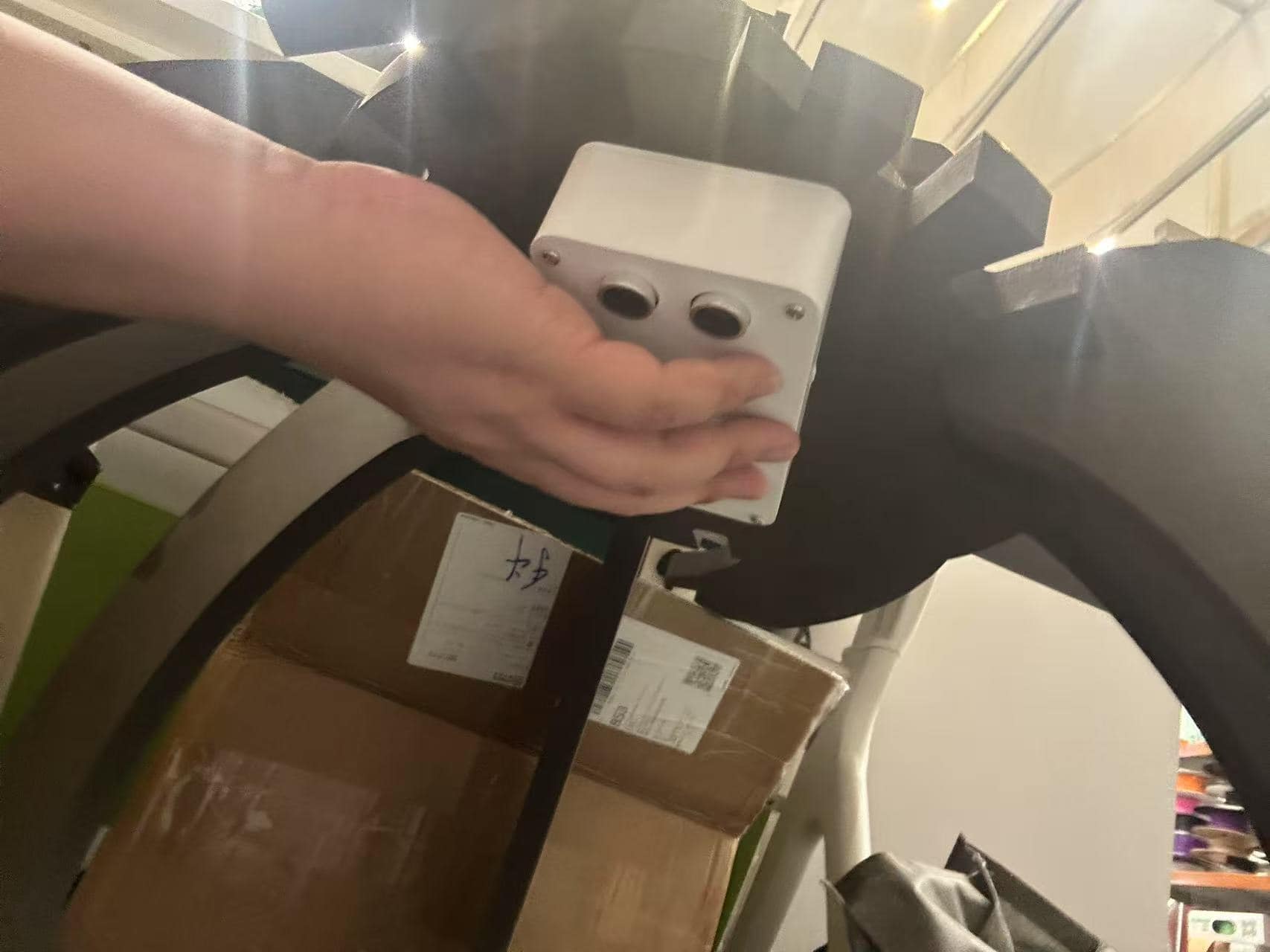
Manufacutring
Finally, the control box is 3D printed and assembled with the sensors. 3D print is additive manufacutring.
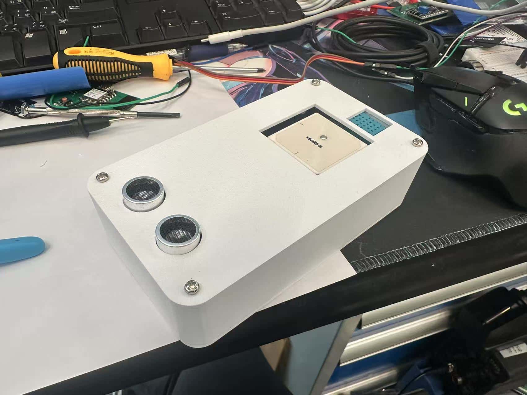
About the circuit connection, refer to system design part.
The control box will be assembled to the top of the cat shelter.
Auto Feeder Modeling
Prototype
In order to achieve the target that the cat shelter can save the stray cat by providing place for living, drinking and eating, a auto feeder is a essential component in this final project.
There are many types of cat feeder. My designed auto feeder is refer to youtube channel Manuel Maeder's design - DIY Arduino project PEDRO.

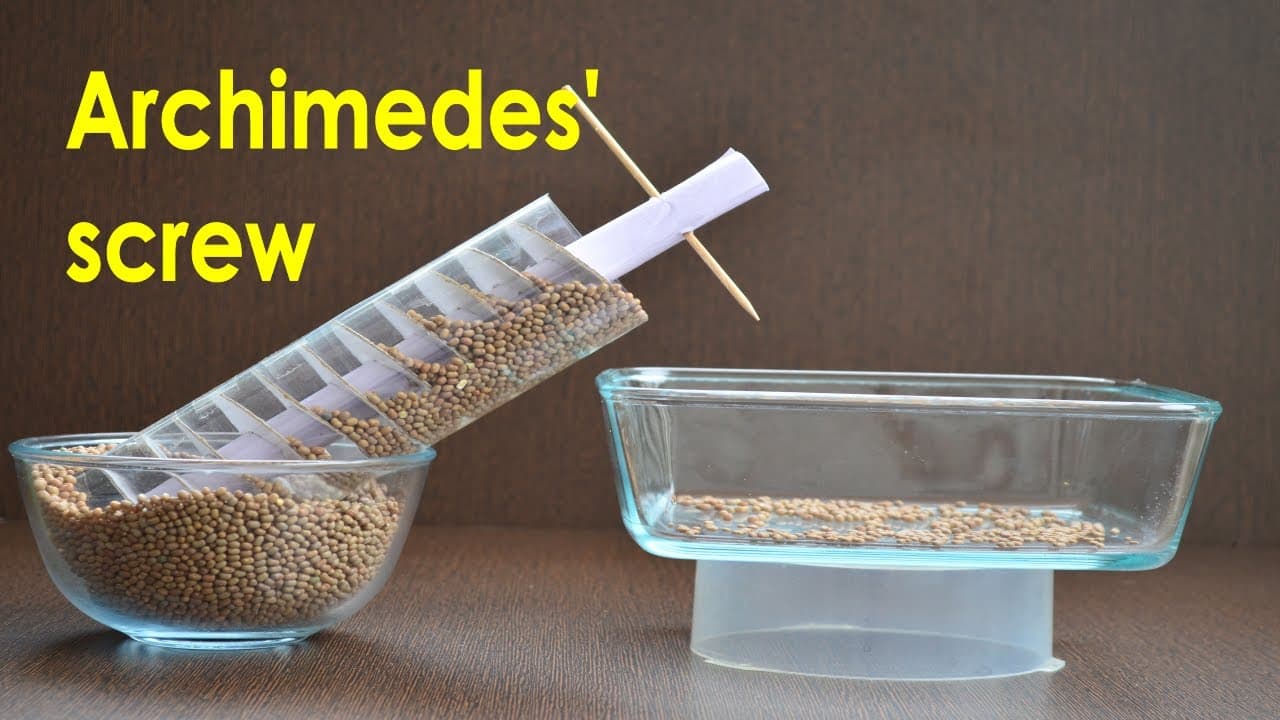
In their design, Archimedes screw mechanism is applied for pushing the cat food.
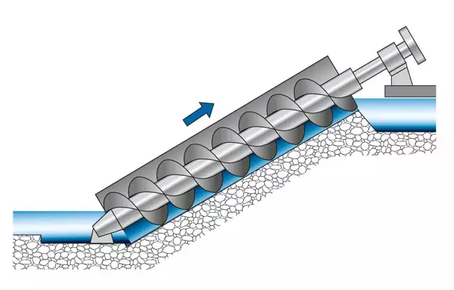
Archimedes screw is used for lifting water from a low-lying body of water into irrigation ditches, water is lifed by turning a screw-shaped surface inside a pipe. This mechanism can also used for pushing small particles such as cat food.
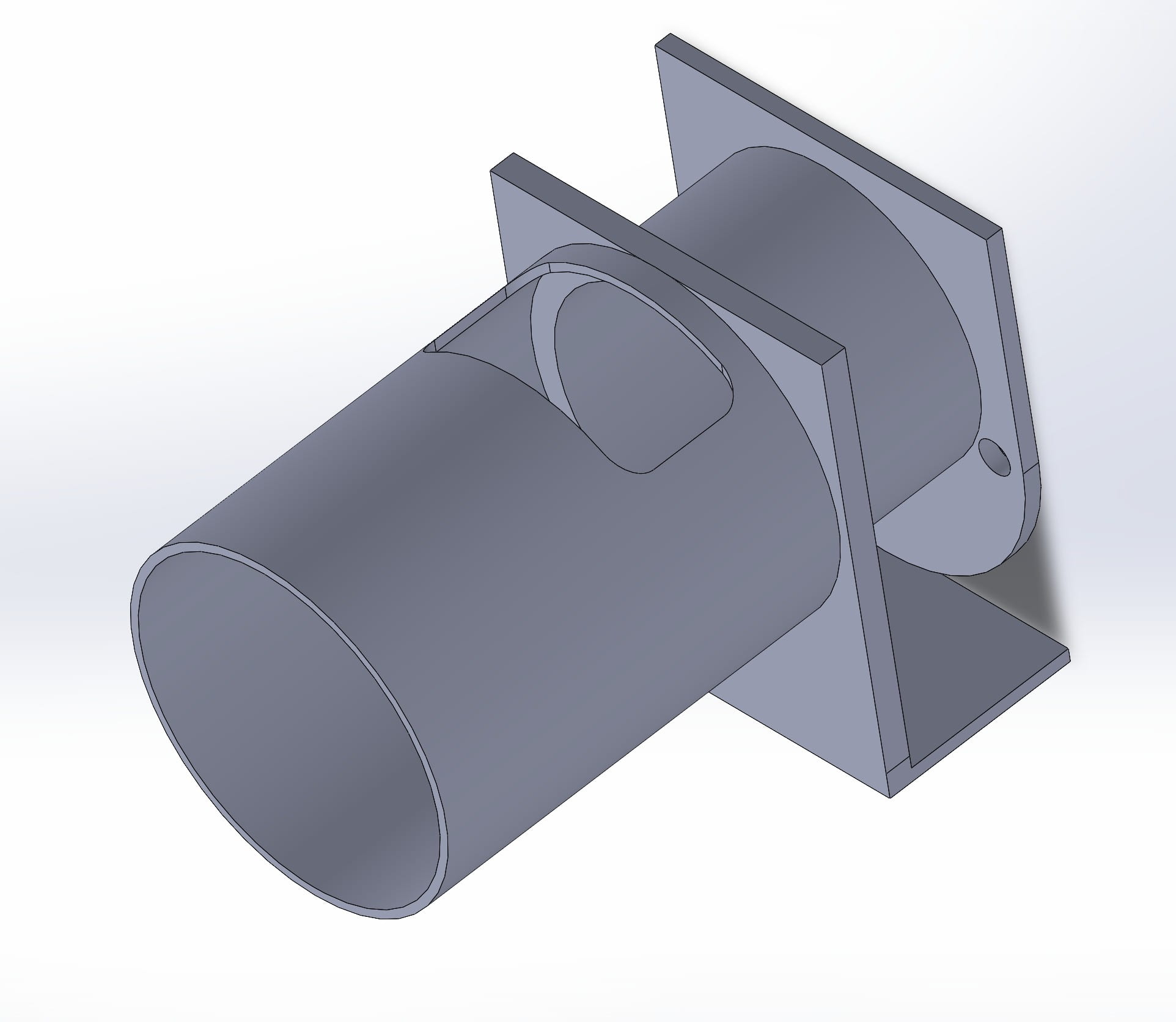
In order to test the feasibility of the mechanism, I modeled a food-feeding tester which is driven by 28BYJ-48 Stepper Motor.
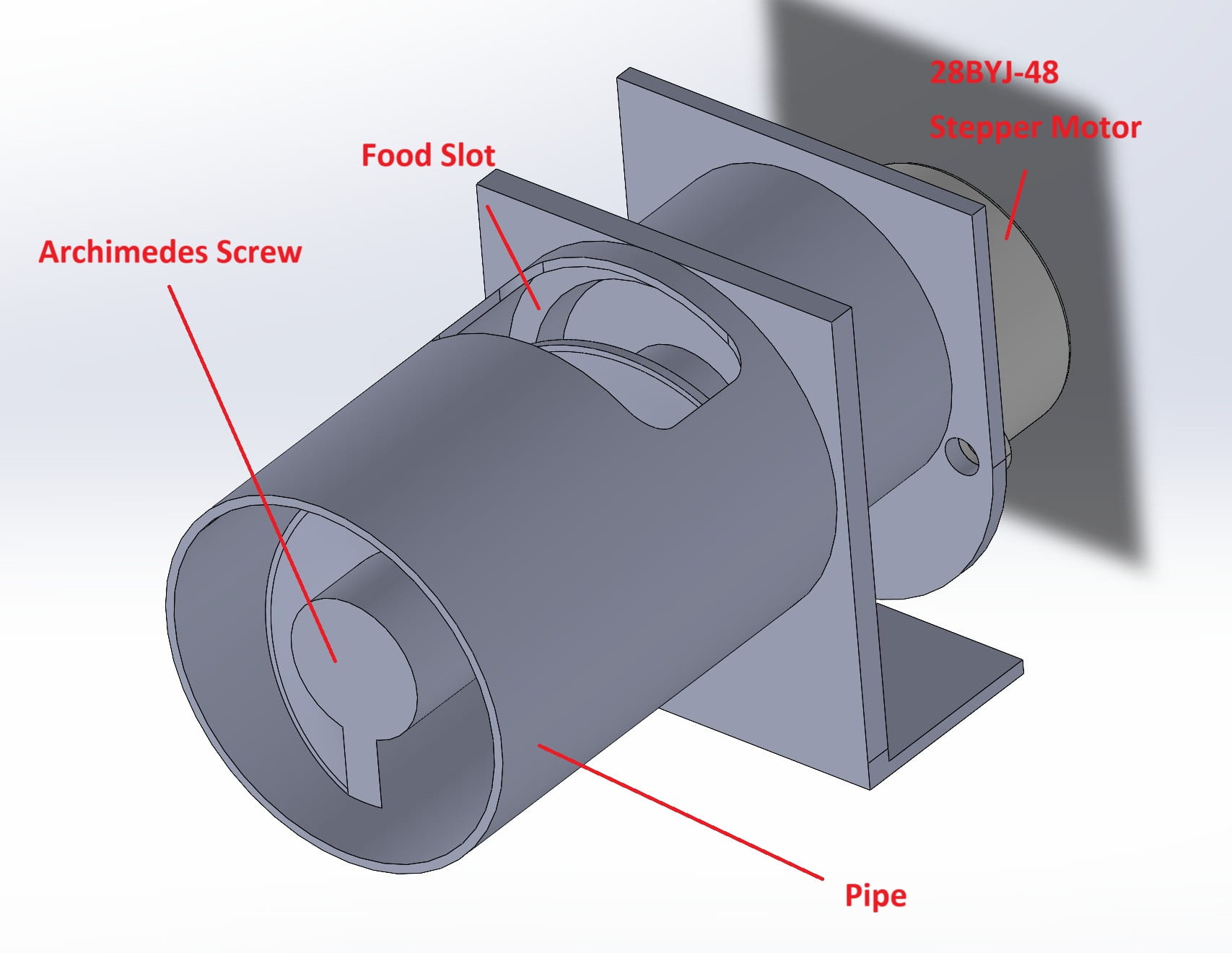
There're 3 parts in the tester.
- 28BYJ-48 Stepper Motor
- Pipe
- Archimedes Screw
There's a slot for inserting food to the pipe.
In the following documentation, I will explain how to design Archimedes screw briefly.
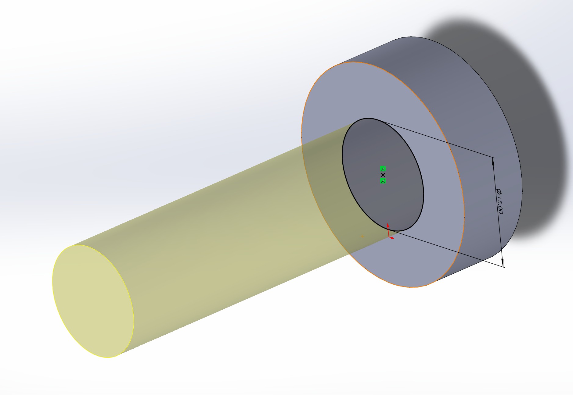
First, build a cylinder which's size is fit to the connector of stepper motor. Then, draw a 30mm diameter circle as sketch.
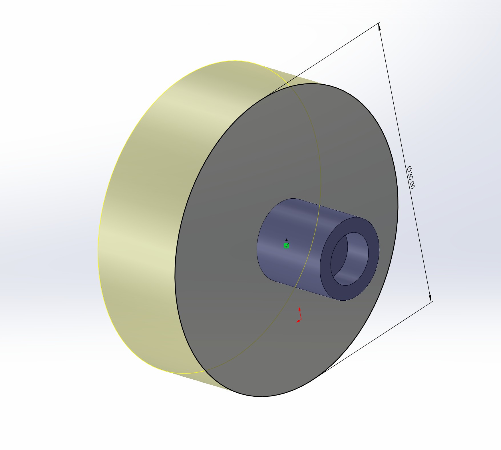
Draw a circle with 15mm diameter, and extrude it for 50mm.
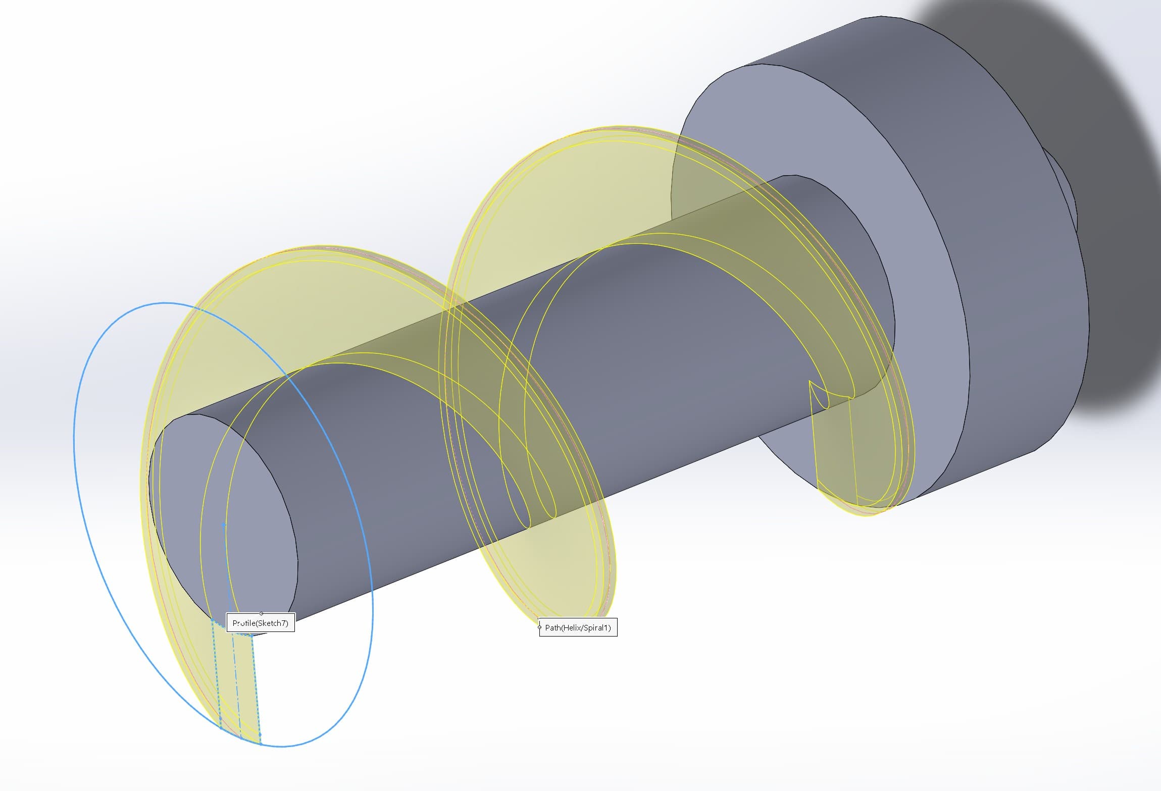
Then, use the Helix and Spiral tool to draw the sprial line.
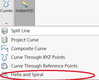
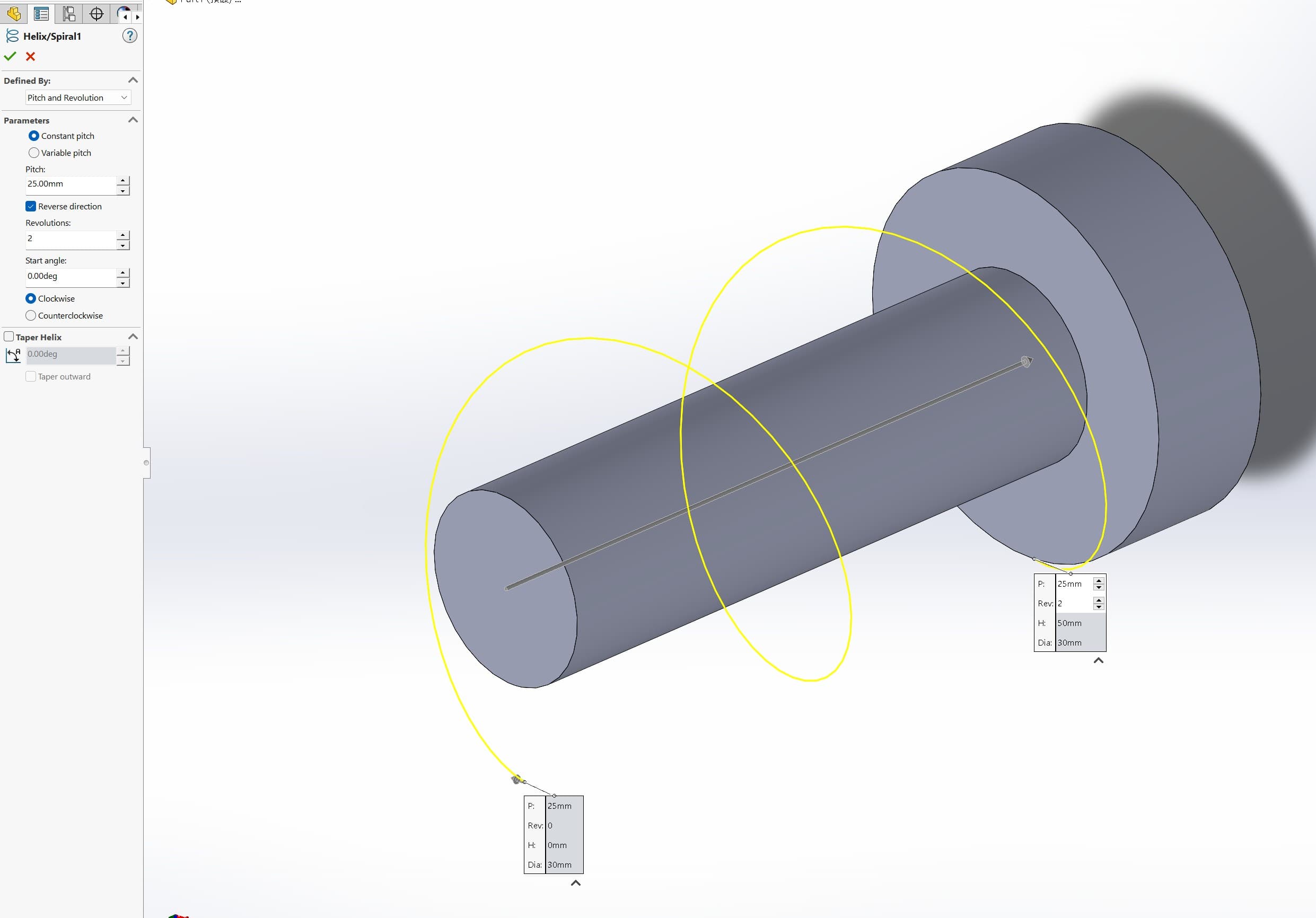
The parameters of sprial line is:
- Pitch: 25mm
- Revolution: 2 turns
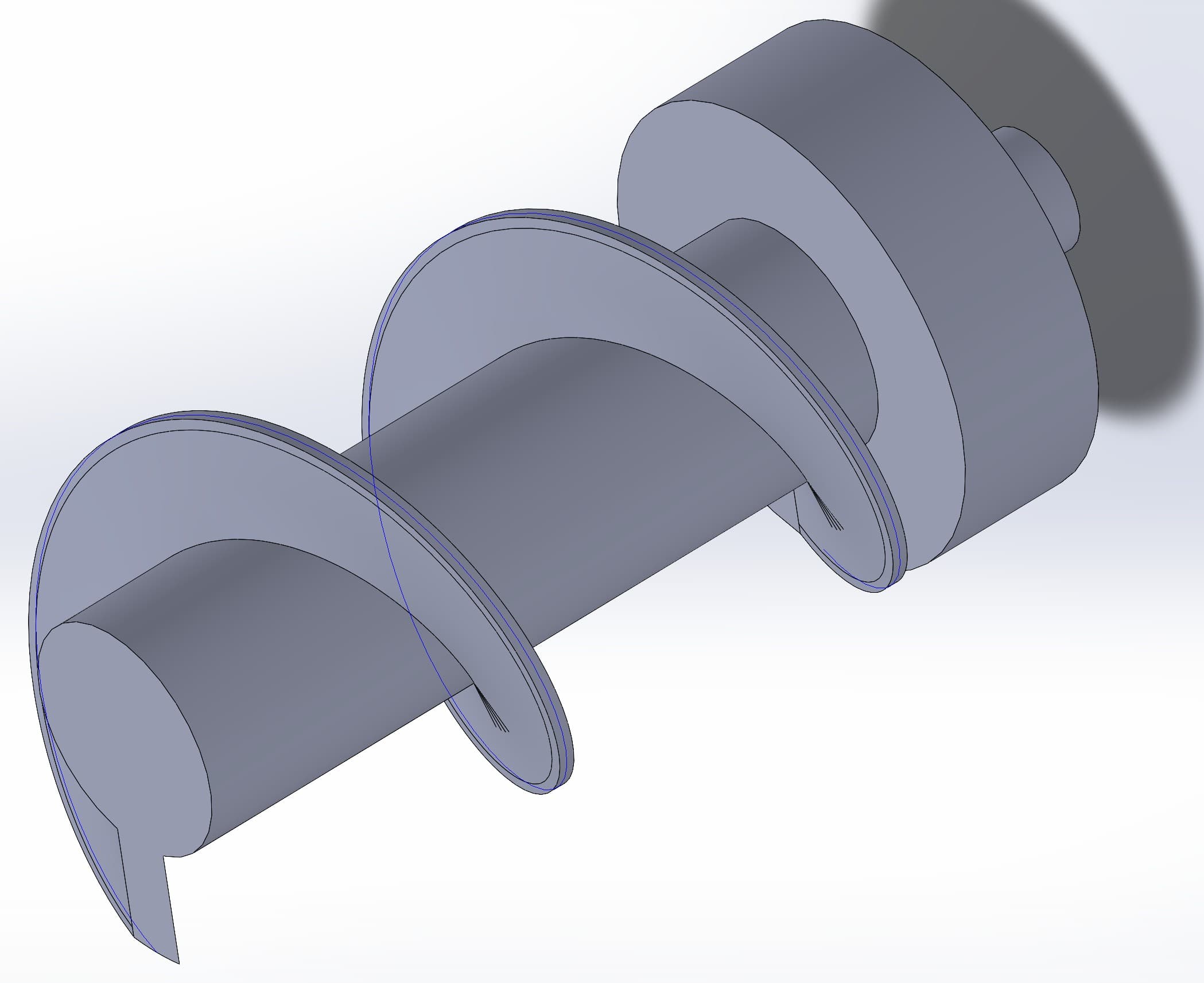
Then, draw a sketch and sweep it.
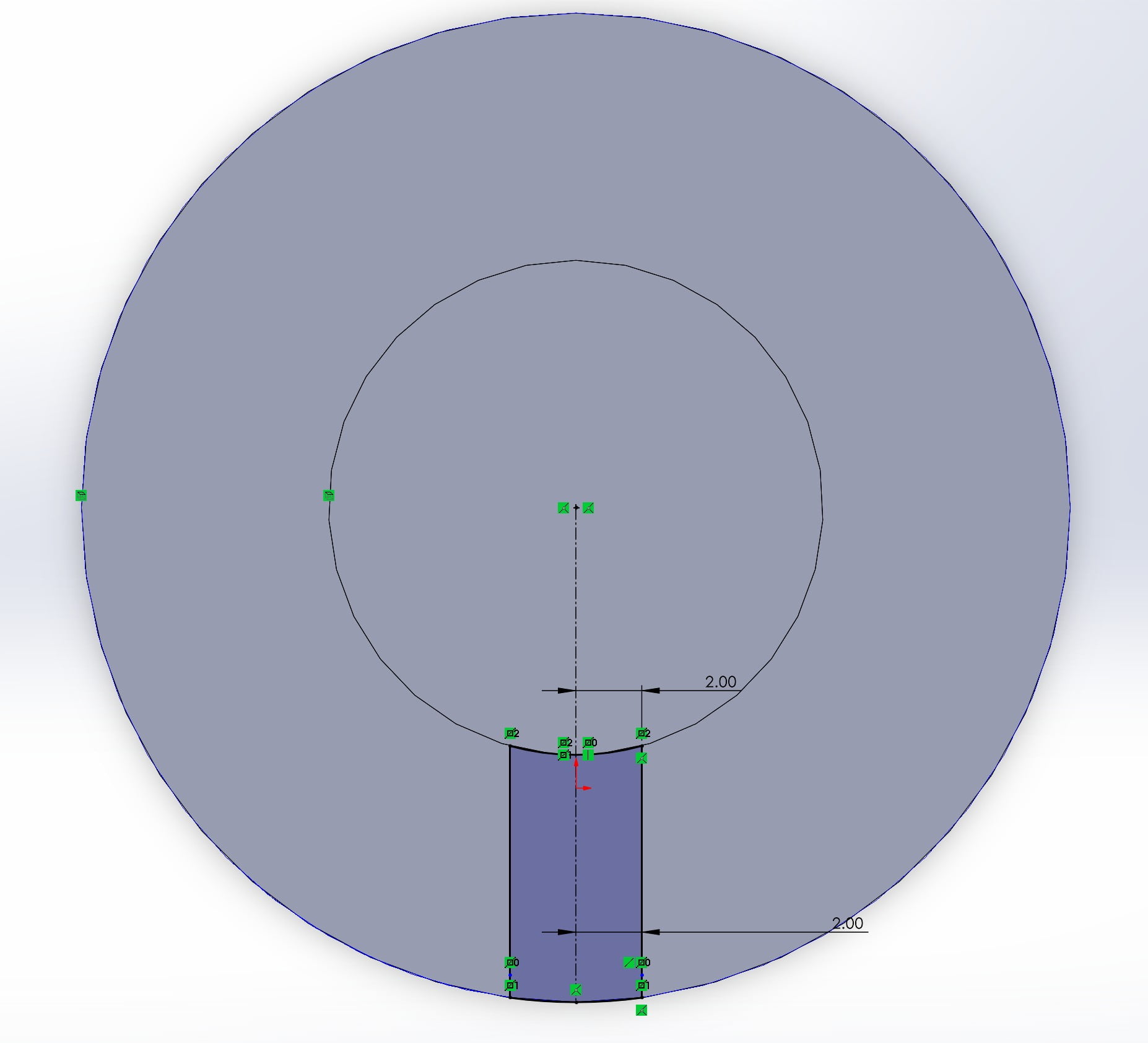
A simple Archimedes screw is finished!!
Then, about the design of pipe, some variables should be considered.
As the size of cat food is about 10mm*10mm, the space between the screw at the pipe must lower than 10mm. I keep a space 3mm between the screw (30mm in diameter).
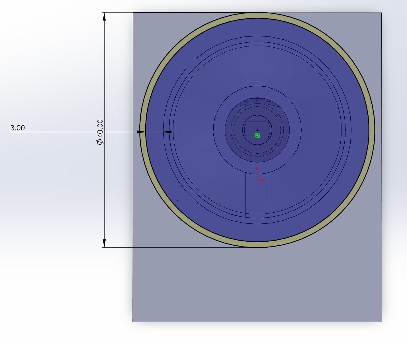
Then, open a slot for inserting the food into the pipe.
The design is printed out and assembled for testing!!
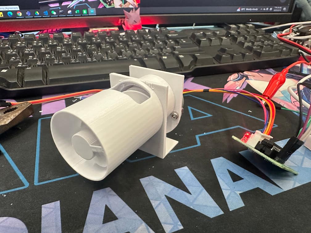
I put some bolts into the slot and bolts can be pushed out of the pipe!!!
Feeder with water bowl (Version1)
Refer to Manuel Maeder's design, I designed the feeder as a cylinder.
The sectional view of the water bowl is shown as below.
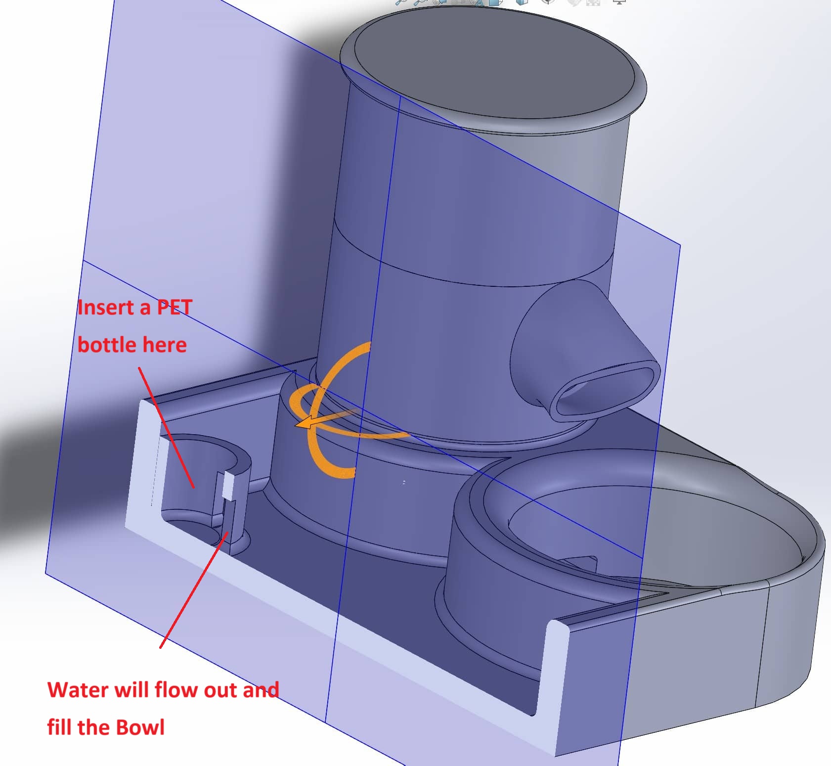
The water bowl part is refer to a model in printable.com. The water will auto-filled to bowl by gravity.
The feeder part can refer to last part of this documentation.
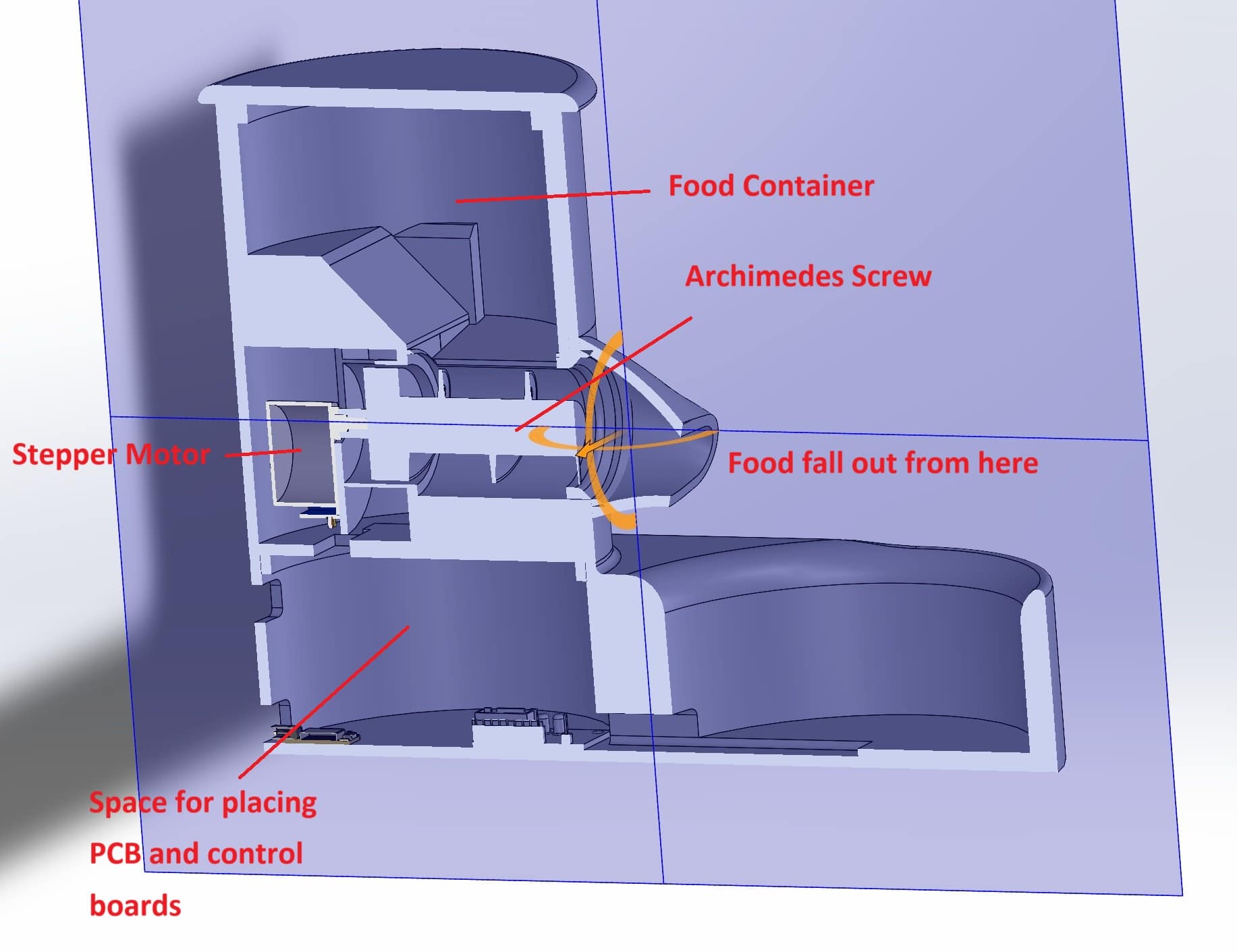
The sectional view of the feed is shown as below.
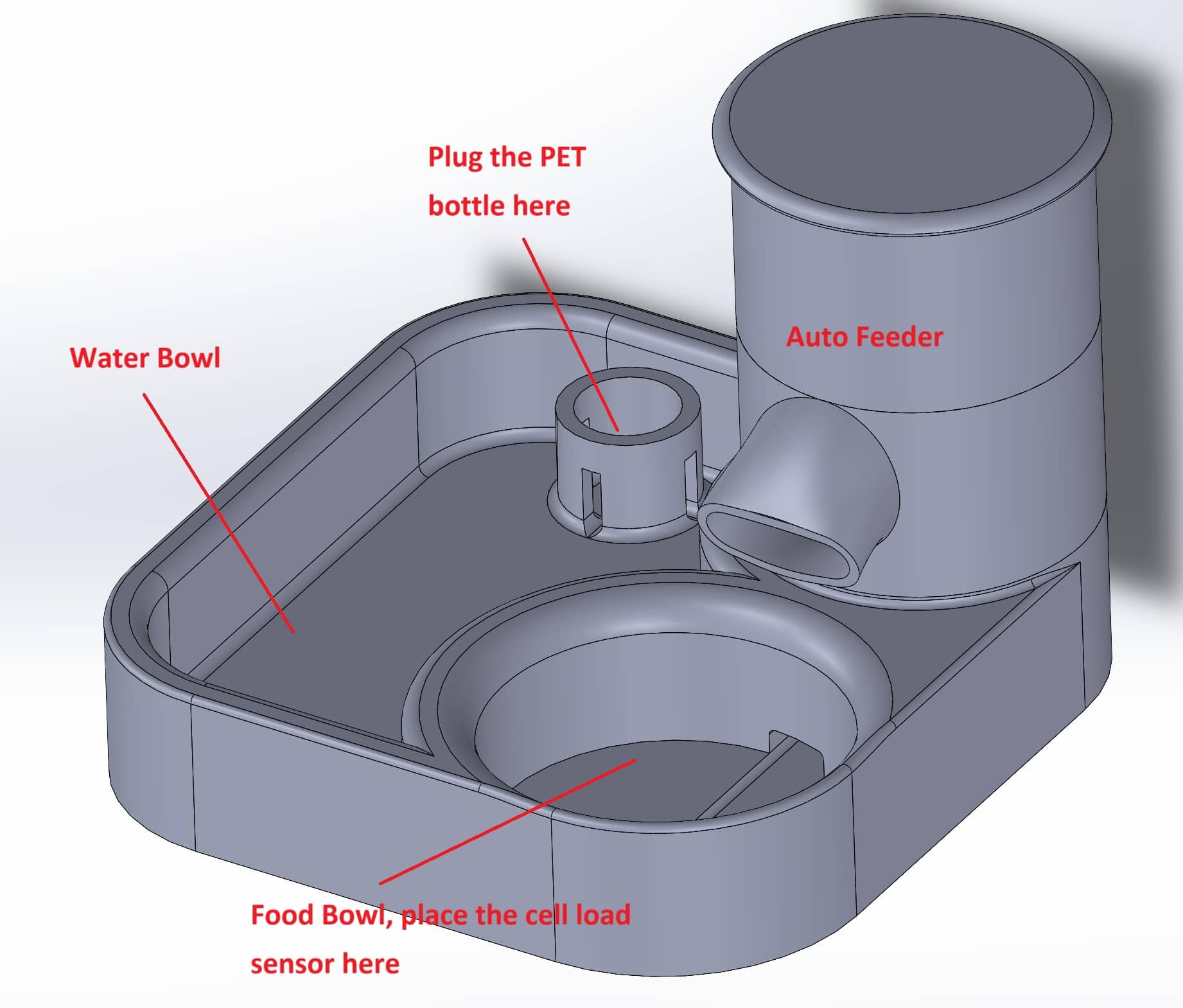
There are 4 parts of the auto-feeder with water bowl.
- Food Container
- Water bowl
- Control Part (Stepper Motor links with Archimedes Screw)
- Chamber for circuit board
Feeder with water bowl (Version2)
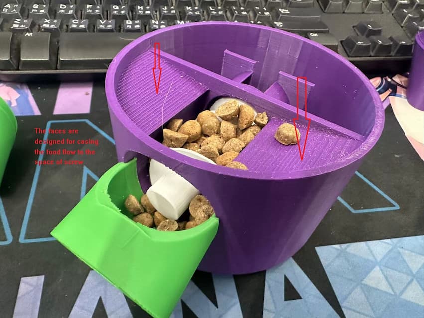
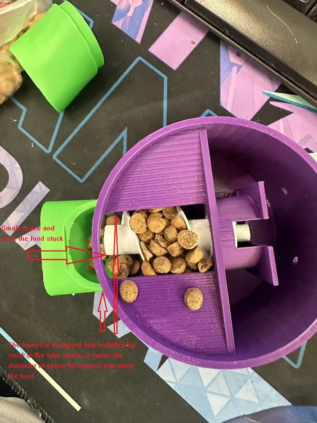
1st Version of the slope which cause the cat food fall into the screw space is about 20 degrees, the whole cat cannot flow down completely. And the funnel is designed by installing into the tube space of screw. It cases the cat food will stuck.
In order to improve the food stuck, the design of internal part will be modified as below.
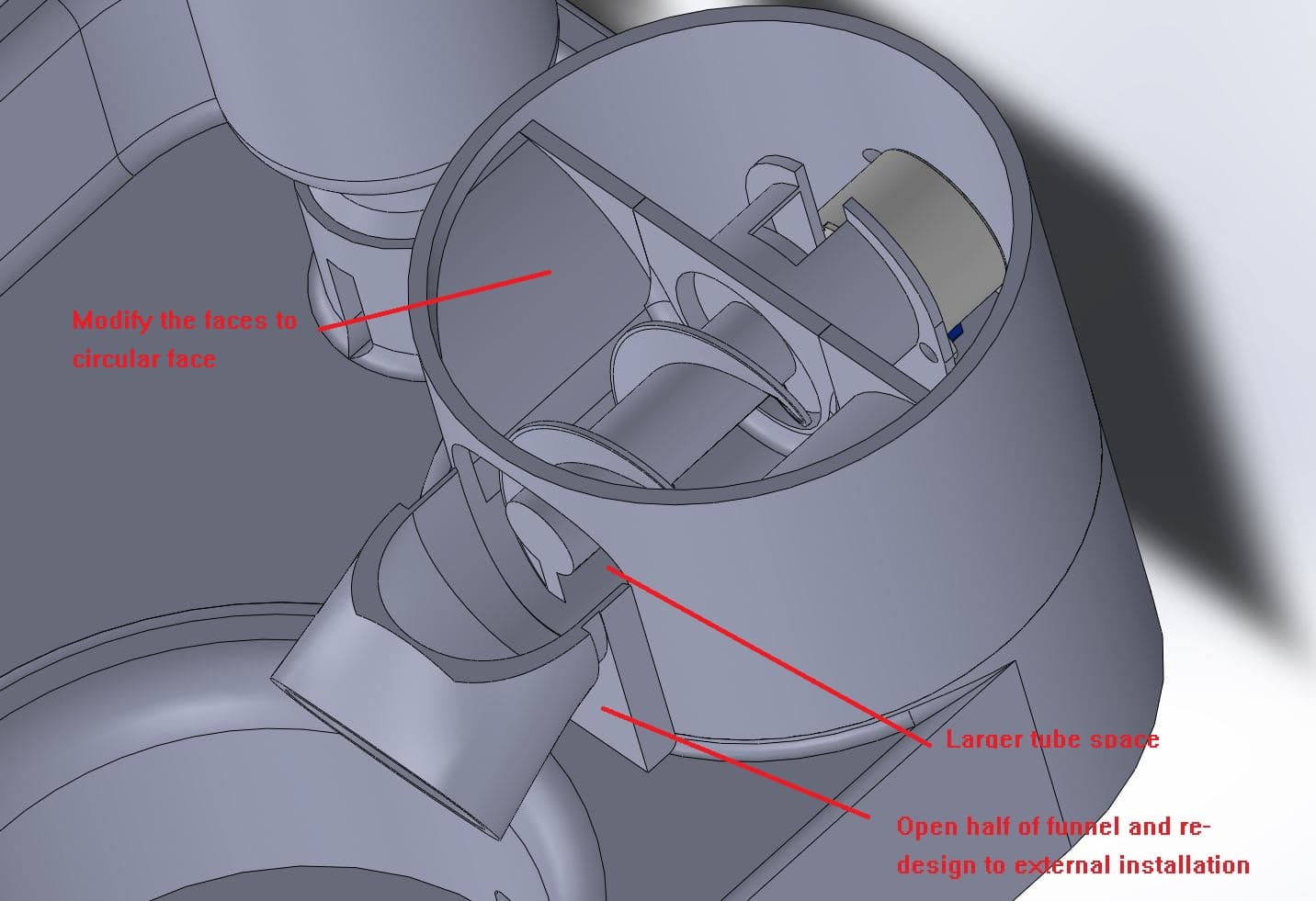
After testing, cat food can be fallen to the tube space completely.
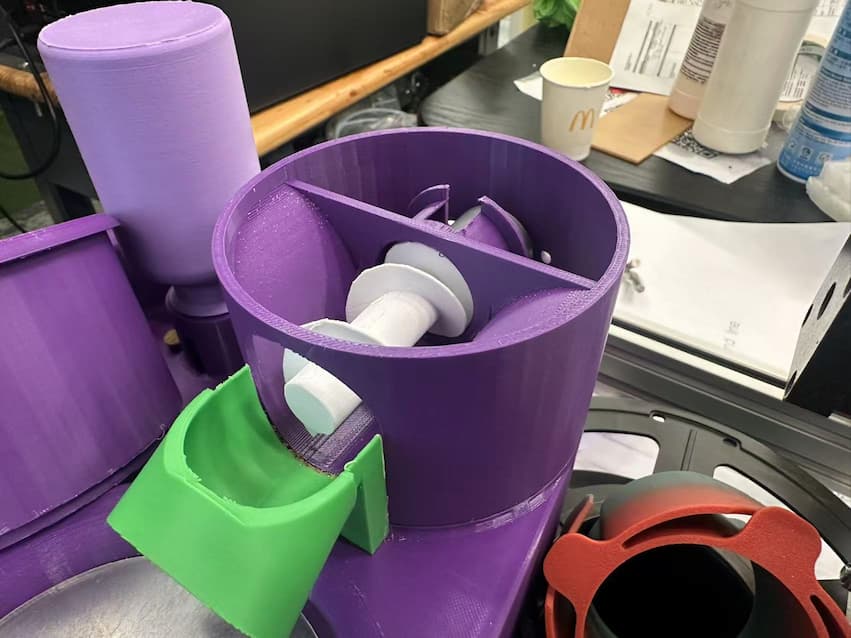
In this version, I also design a bottle for inserting to the bowl part.
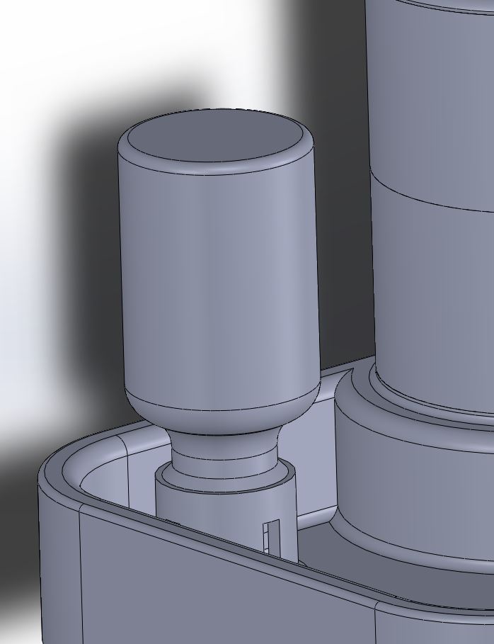
Finally, the design and layout of auto-feeder is finished!!
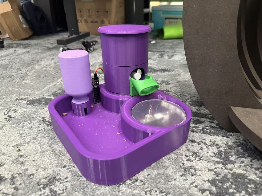
Overall
The external design and layout of my final project is finished!!