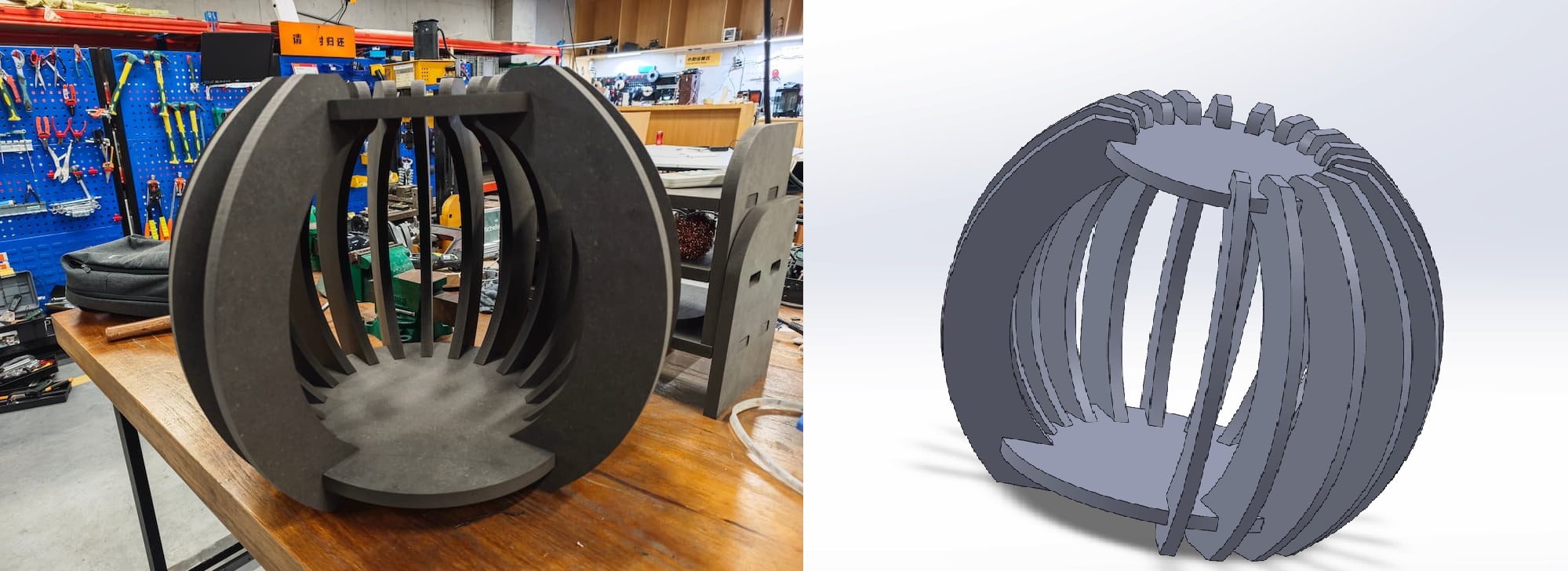
Week7 - Computer-Controlled Machining
File Sharing
The dxf file and the solidworks file are shared in the following link.
The task of the assignment
- Make (design+mill+assemble) something big (~meter-scale)
- Extra credit: don't use fasteners or glue
- Extra credit: include curved surfaces
Knowledge about the Large CNC Machines
When using large CNC machines for cutting, there are several key points, in process:
Choose the right CNC machine: Select a suitable CNC model based on the cutting size, material hardness, precision requirements, etc. Different models have varying power, rigidity, and accuracy parameters.
Use the correct CAD/CAM software: This is very important. There are various CAD design and CAM programming software available in the market, and different CNC machines may require specific post-processors. This is the reason I output both 2D files and 3D files at the same time.
Workpiece clamping and positioning: Wood is relatively soft and easily deformable, so clamping is crucial. Ensure that the workpiece is securely fastened and reasonably arrange the fixtures to avoid interference. Large workpieces may require multiple setups, so the positioning reference should be consistent(the zero point).
Tool selection and control: Choose suitable tool materials, number of flutes, and diameters based on the wood type and cutting requirements. Pay attention to controlling the tool overhang to avoid vibrations that affect machining quality. Check for tool wear before each use.
Cutting parameter setting: Set the spindle speed, feed rate, and cutting depth according to the wood hardness, tool type, etc. Usually, multiple debugging sessions are needed to find the optimal parameters.
To sum up, I need to choose the appropriate CNC machine and software based on specific requirements, draw the 3D model of the part using CAD, write the toolpath using CAM software to generate G-code, import the code into the machine, install the tools and properly clamp the workpiece, set appropriate cutting parameters.
Machine
This is the Machine we using for CNC cutting in ChaiHuo:
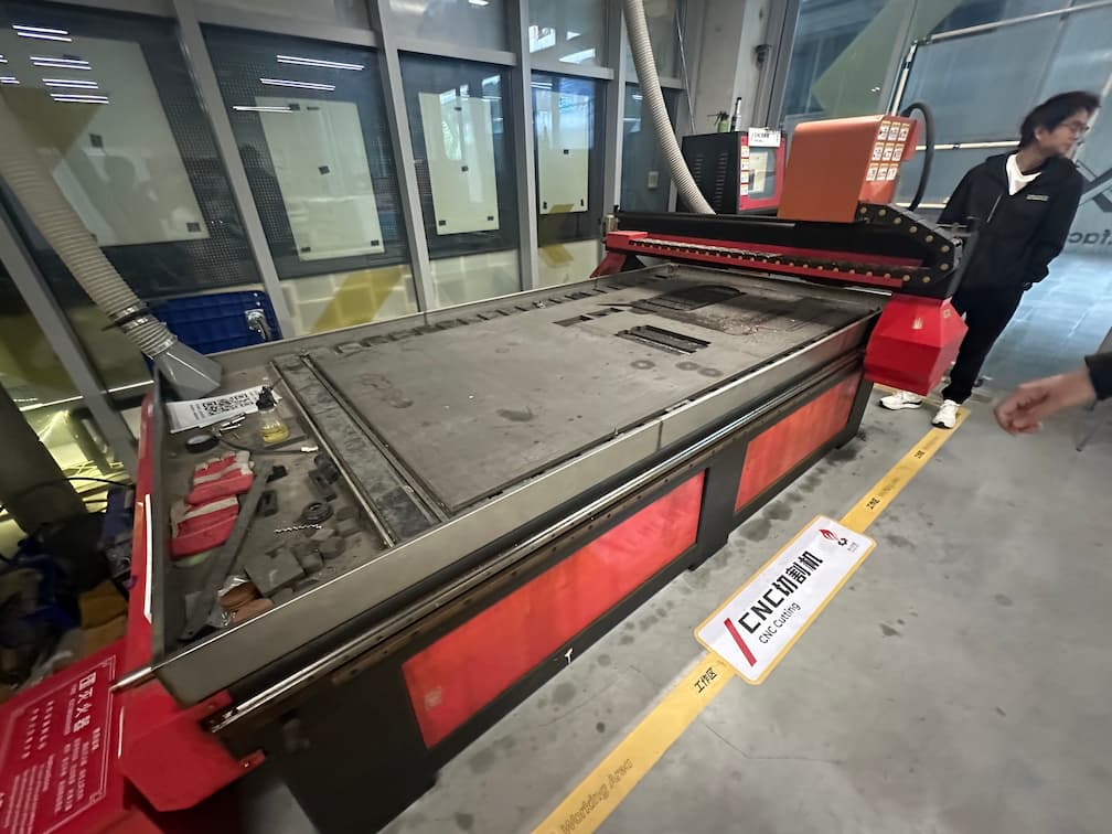
It's brand name is ZhongTaiKe.
The specification of the CNC as below:
| Positioning Accuracy | RPM | Control Command | No-load speed | Working speed | Diameter of Tools | Power of Spindle | Cooling System | Weight | Power |
|---|---|---|---|---|---|---|---|---|---|
| +-0.15/300mm | 0 - 24000 (r/min) | G Code, U00, mmg , nc | 0-20000mm/Min | 0-15000mm/Min | 3.175mm, 4mm, 6mm, 8mm, 10mm, 12.7mm | 3kw | water pump | 2200kg | 380v50Hz |
Knowledge about CNC machining
How does whole thing work It requires "G-code" to make the CNC machine work. And there are multiple ways to generate G-code.
G-code is a language that is used to control CNC machines. It provides the necessary instructions for these machines to perform tasks such as cutting, drilling, or engraving materials. The language includes commands that dictate the movement of the machine along its axes, control the speed of the movements, manage the tool operations, and other specific actions required to shape the material according to precise specifications.
For the group training, I understand the large CNC machining technological process:
- Safety
- Origin Point Calibration Return the machine to origin and set the speed (15000mm/min) and looking for the original point.
Here we using 5000mm/min and 8mm mining to do the test cutting
MasterCAM X6 Setting
- Use MasterCAM X6 to convert DXF file to G-Gode.
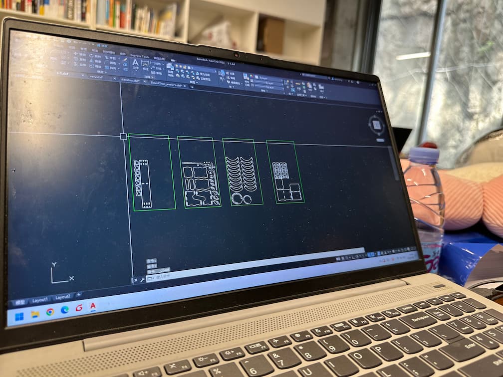
Import the DXF file.
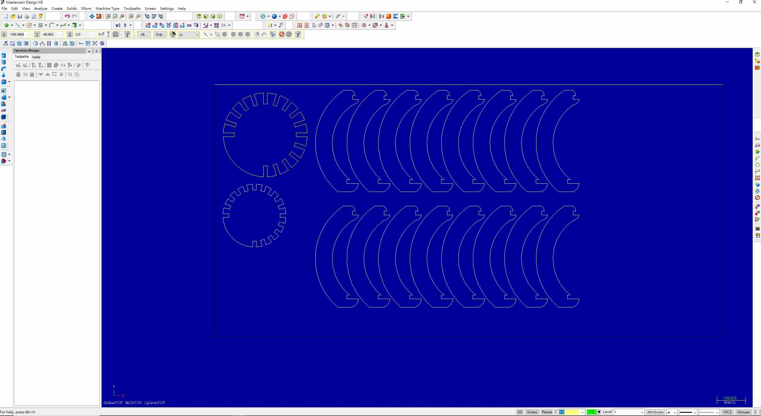
Then, add Contour cutting in the Mill toolpaths selections.
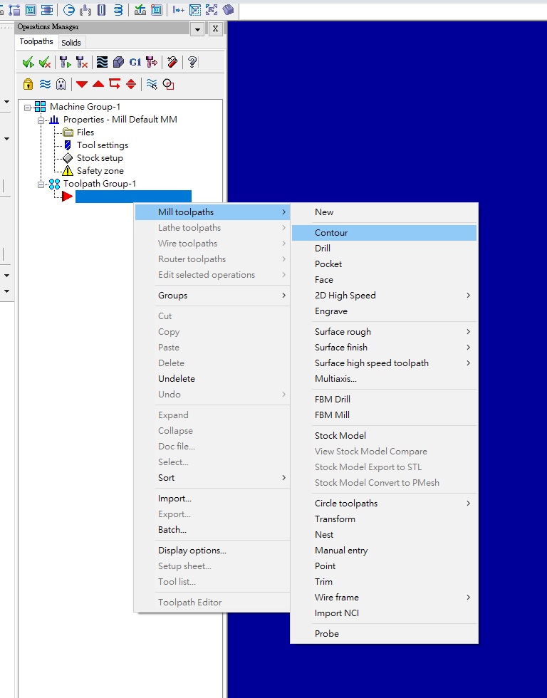
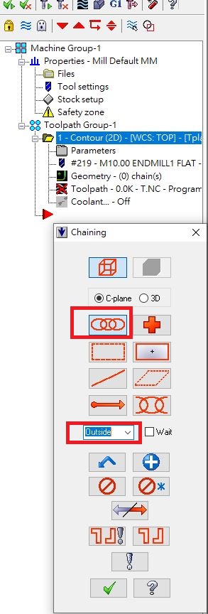
Choose "Chain" and selection "Outside", as my cutting files only exists the outline.
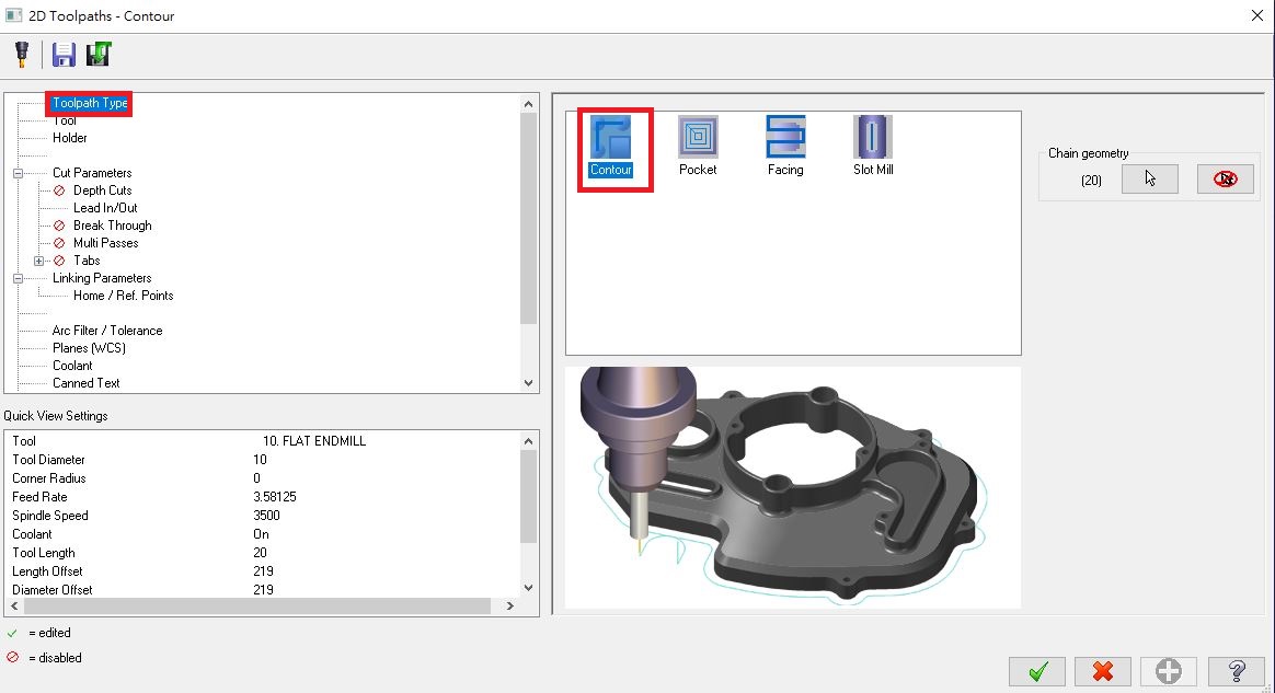
There's a windows come out and I setup the parameters about the tools.
First I will setup the ToolPath Type as Contour.
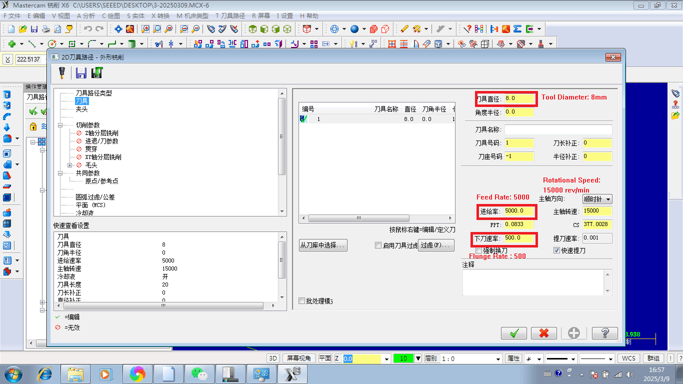
Go to "Tool" selection, then setup the toolpath as 8mm diameter tool. Set the tool parameters as below:
- Rotational Speed
15000rev/min - Feed Rate
5000 - Plunge Rate
500
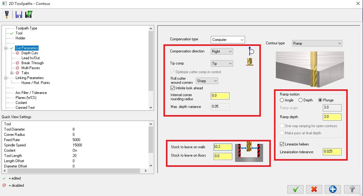
Go to "Cut Parameters" and setup the contour type as ramp, setup the Ramp motion as Plunge and the ramp depth is 3.0. Setup the Compensation direction as right.
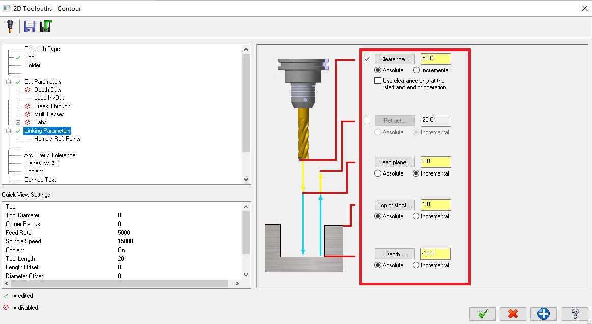
Go to "Linking Parameters" and setup the clearance as 50 in Absolute, Feed plane as 3.0 in Incremental, Top of stock as 1.0 in absolute and Depth as -18.3(The thickness of HDF board is 18mm) in absolute.
Then, go to verify function as start the simulation.
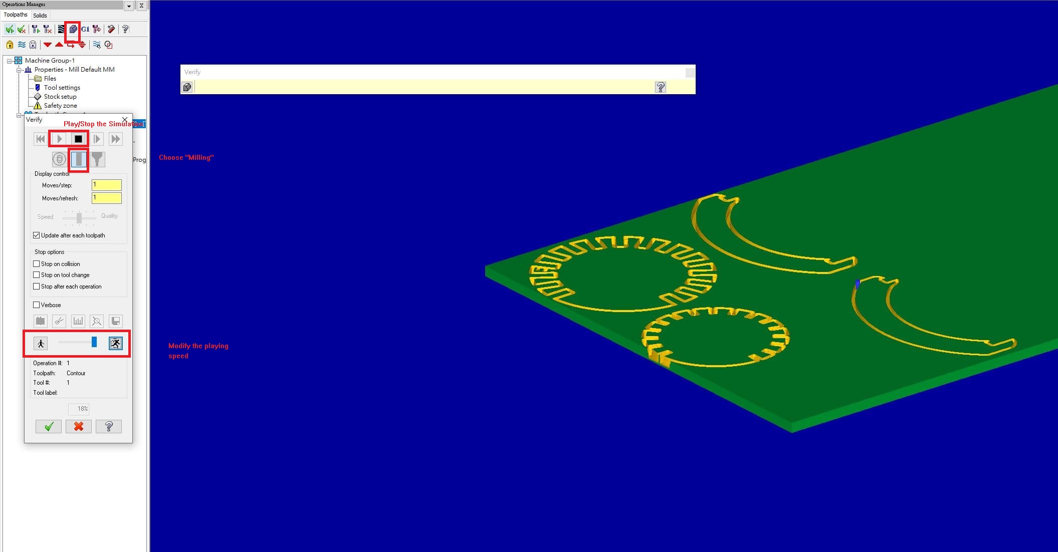
There's the simulation video!!
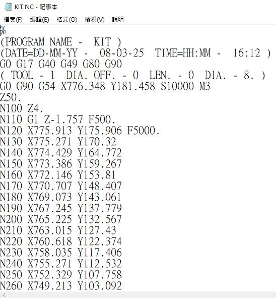
Finally, generate the G-Code file. (.NC files)
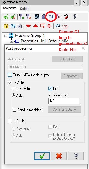
Here's my G-Code file.
Design
I have designed a type of cat shelter during designing the final project with the 3mm wood plate.
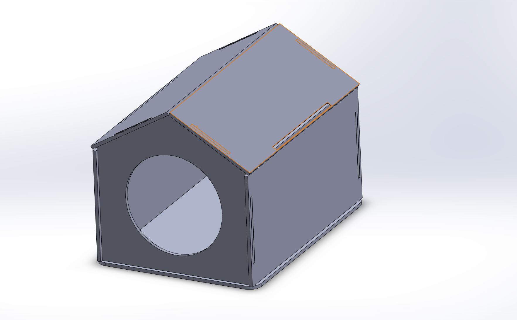
It can not afford a 8kg cat. Then I find the other material and type of cat shelter.
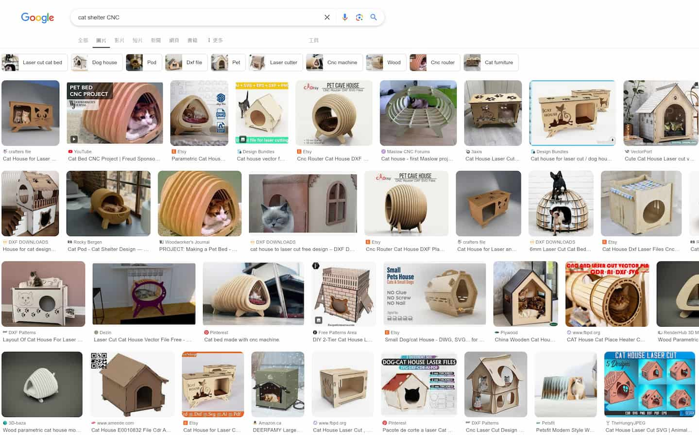
Considering the designed cat shelter is used for stray cats, it means the cat shelter which will be placed outdoor environment. So I also consider about the cat shelter can also as a artwork.
I found a type of cat shelter in etsy.com and looking for the shelter as below. And I found the vector files sample of this cat shelter.
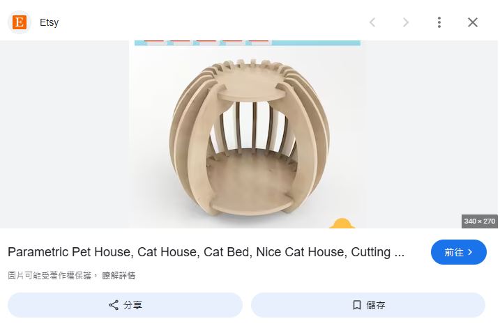
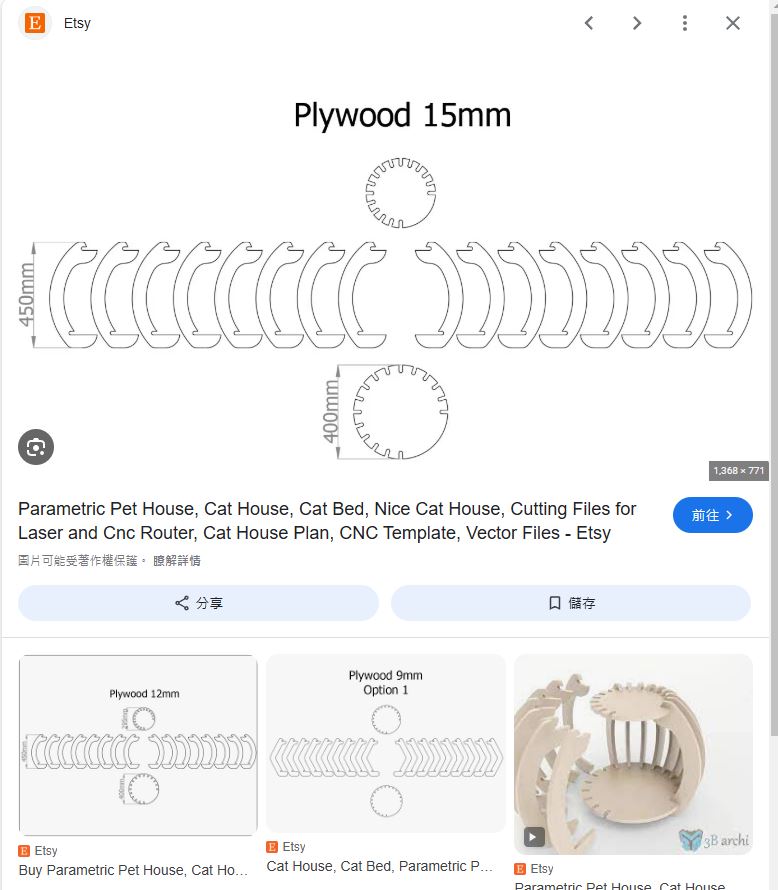
Then, I start designing this cat shelter by 3D software - Solidworks.
As it is a assembled project, I will design the 3D model by top-down designing.
I start modeling the cat shelter from the base part.
Base Part
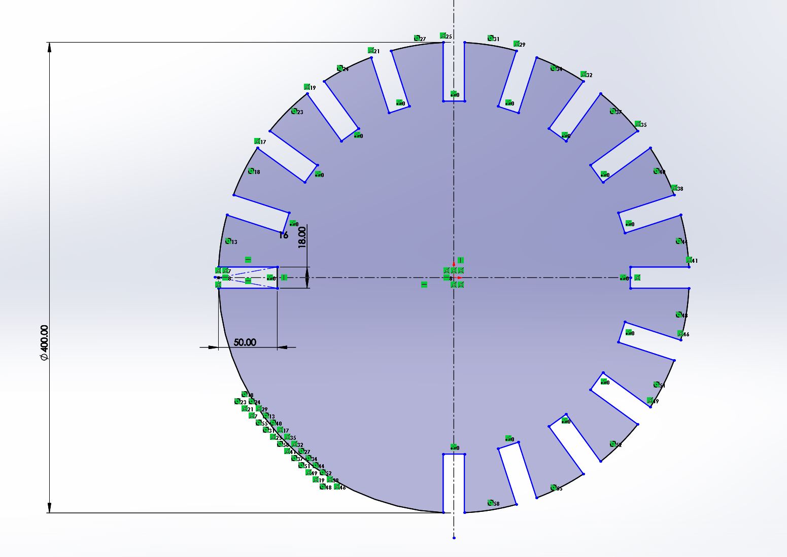
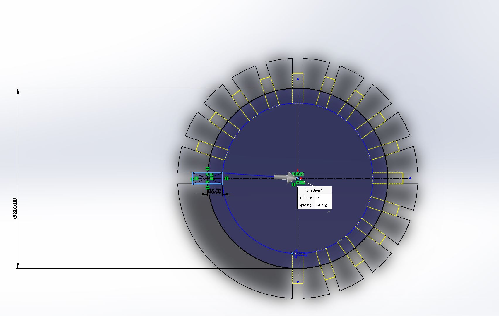
The base design is started from a diameter 400mm circle.
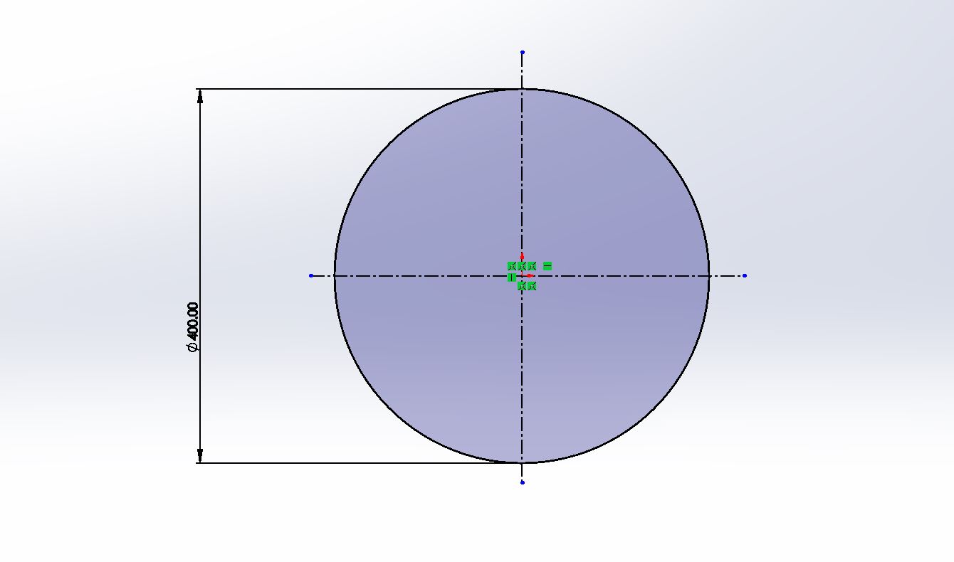
Then, draw a 100mm*18mm rectangle as below.
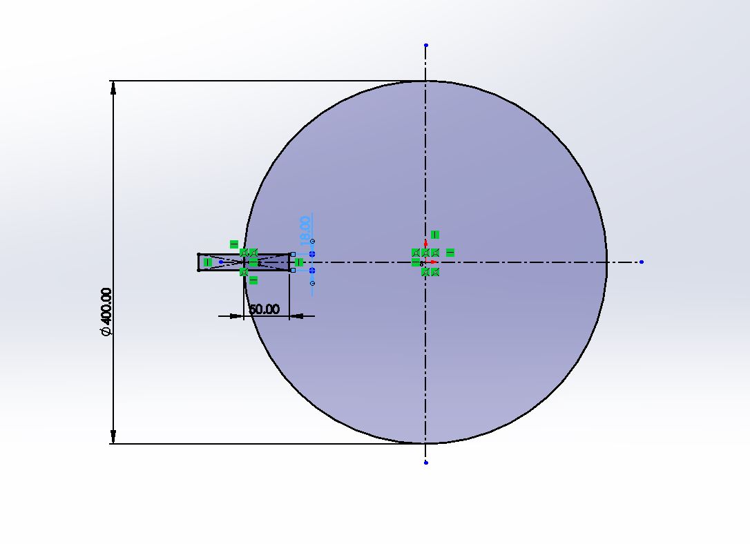
Use Circular sketch pattern tool to copy 16 rectangles in circle 270 degrees.
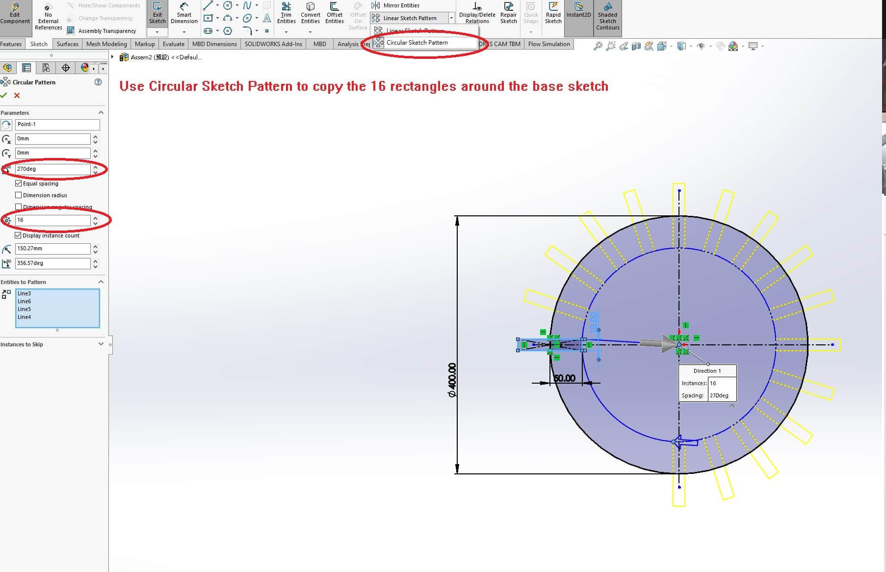
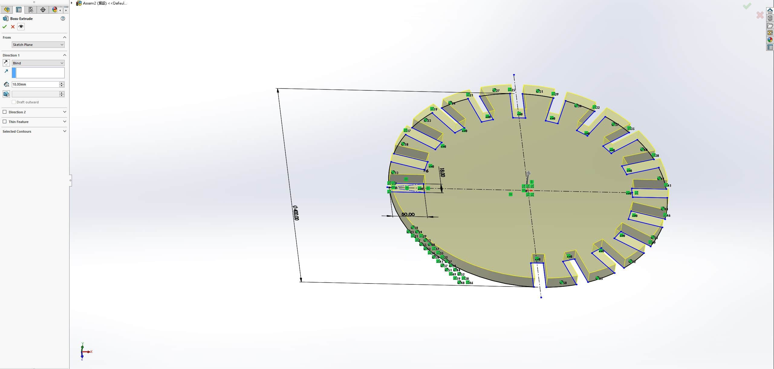
Use Trim tool to remove the sketch lines and extrude the sketch as 18mm, which is the thickness of our cutting material.
Top Part
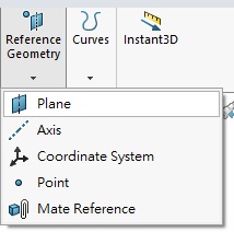
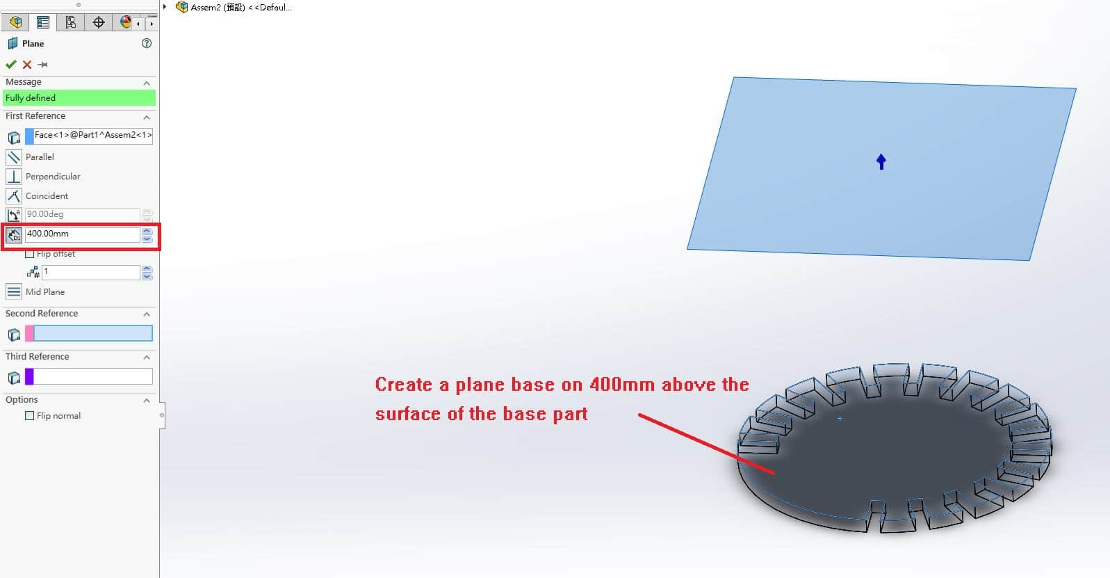
Use Plane tool in Reference Geometry to create a plane base on 400mm above the surface of base part.
Then, repeat the step as drawing the sketch of base part with 300mm diameter circle and 50mm * 18mm rectangle. Extrude the sketch with 18mm thickness.
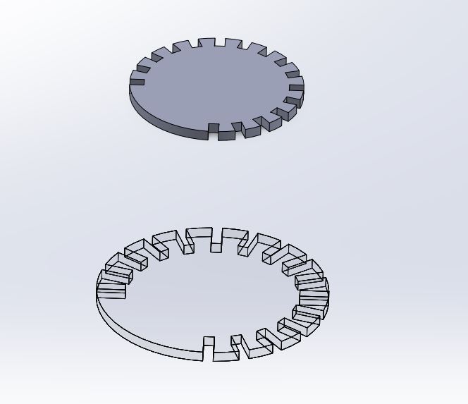
Side Part
Choose Front view and draw a new sketch as below.
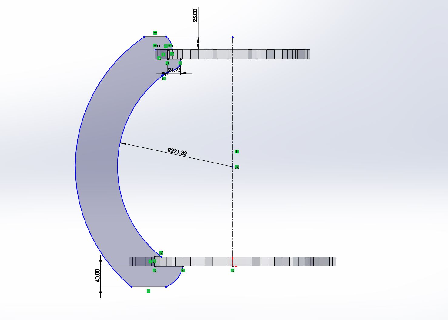
It is the supporting parts between base part and top part, a thick design is necessary or it will be broken because of heavy weight.
Made up
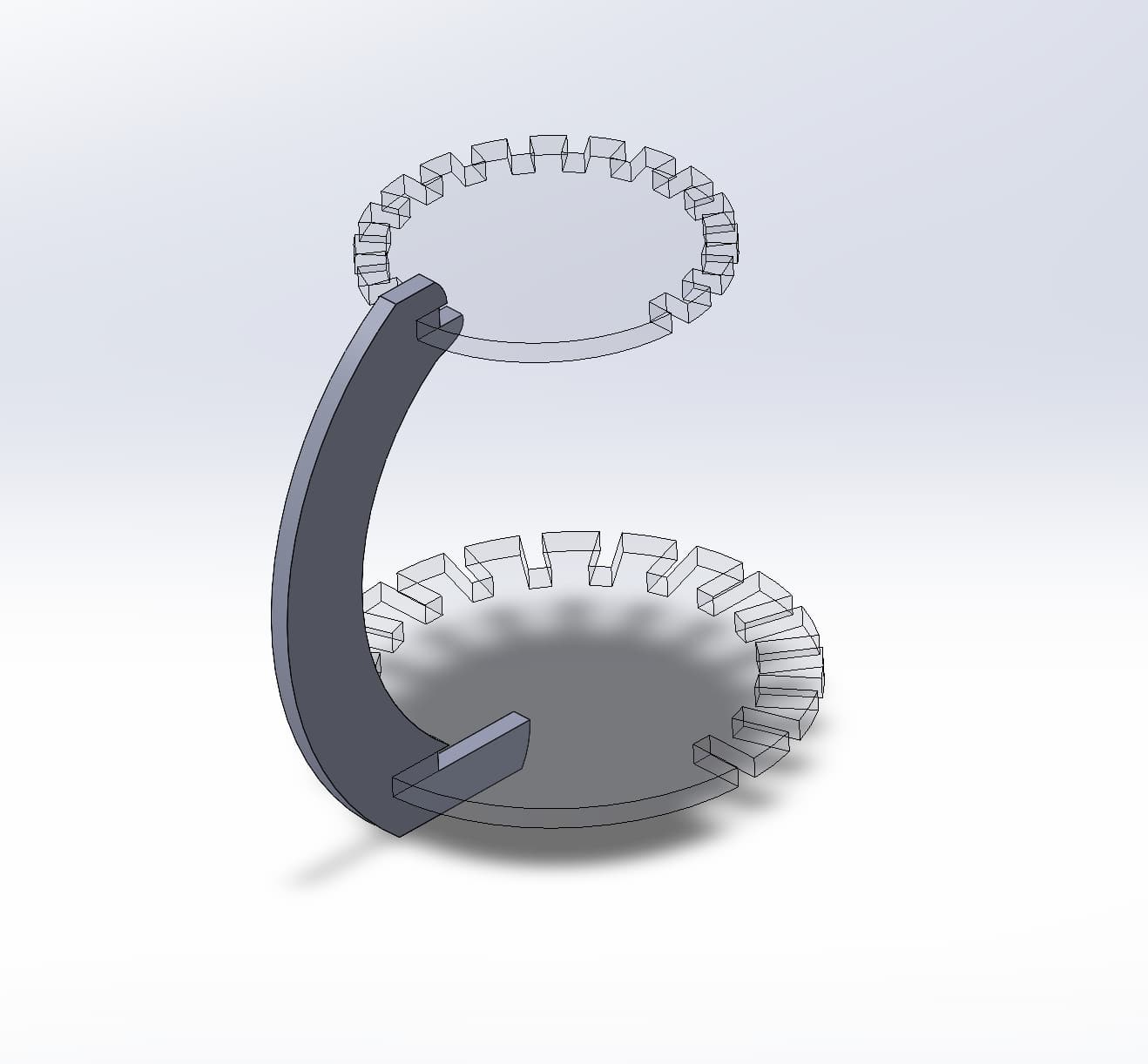
The assembling parts is shown as above, there's only one side part to support. It's not enough to maintain the structure of the shelter.
Finally, I use 16 side parts to maintain the base part and top part.
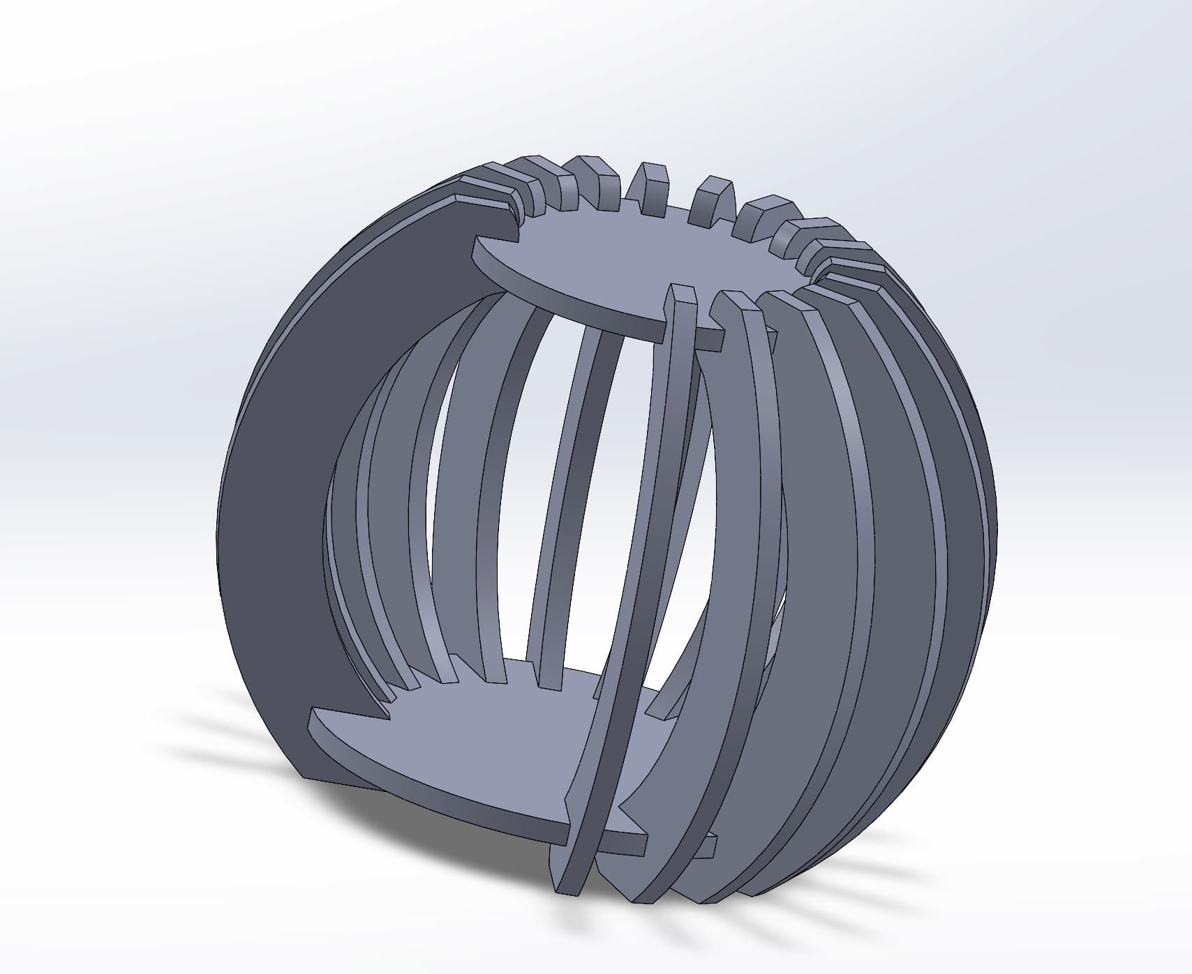
An artwork-designed cat shelter, finished!! This shelter will be used for my final project.
CNC Cutting Process
During the cutting process, we followed these steps:
- Place and fix Materials(HDF Board)
- Adjust the Processing Origin Point
- Turn on the Air Treatment Equipment
- Confirm Processing Settings
- Monitor the CNC Cutting Process
- Clean the Processing Area
Assembling the Cat Shelter
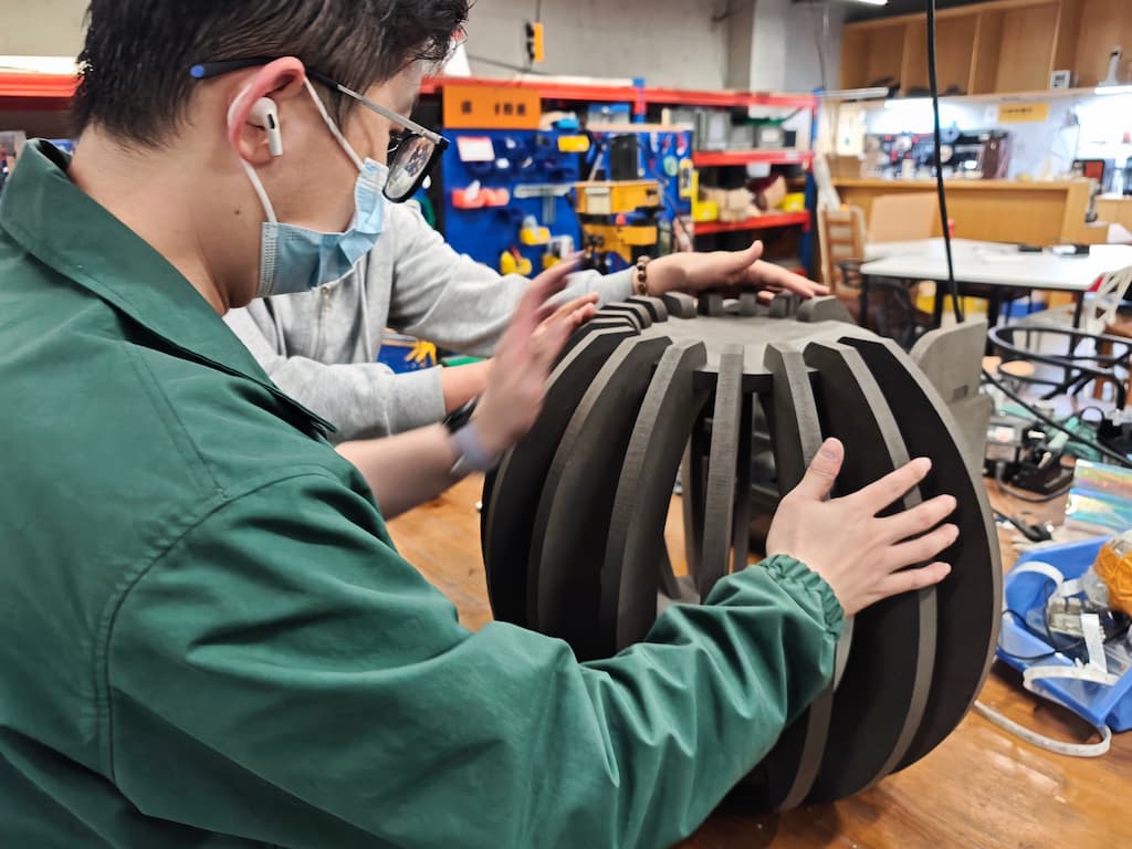
After cutting all parts,
- Check the Parts
- Inner corner adjustment
- Assembly Connection
Use a rubber hammer to know the adjusted board materials to complete the product.
Comparing with the design 3D files.
