Final Project - System Design(Electronics)
File Sharing
Essential function of the cat shelter
Some essential functions are listed of my final project - cat shelter as below:
- Getting the position data of cat shelter
- Detect whether a cat get in the shelter
- Detect the remain food and water by weight or level
Costs of Materials
There's a list about the sensors to satisfy the function which listed
| Sensor/Microcontroller | Function | Price | Count | Link |
|---|---|---|---|---|
| XIAO ESP32C3 | Controllers for getting sensor data | 9.99 | 2 | link |
| RYS352A GNSS Antennia | Getting position data | 10.00 | 2 | link |
| HX711 load cell sensor | Sensing remain cat food | 6.79 | 1 | link |
| HS-S37A Water level sensor | Sensing remain water | 1.79 | 1 | link |
| HC-SR504 Ultrasonic sensor | Detect the cat inside the shelter | 9.99 | 1 | link |
| 28BYJ-48 Stepper Motor | For activator of auto feeder | 14.59 | 1 | link |
| WS2812B LED | For light display of auto feeder | 13.99 | 1 | link |
Here's the designed system in block diagram.
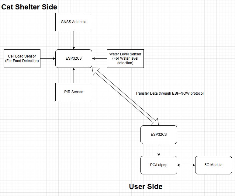
In cat shelter side, many sensors are connected to the microcontroller and send the sensing data to the user side through ESP-NOW protocol. It simulate there's a central control station of the cat shelters.
A website-based web server will be built in user side, which is used for showing the sensing data or status of the cat shelter. I can refer week 11 assignment to build up a web-server for showing the sensing data in a user interface.
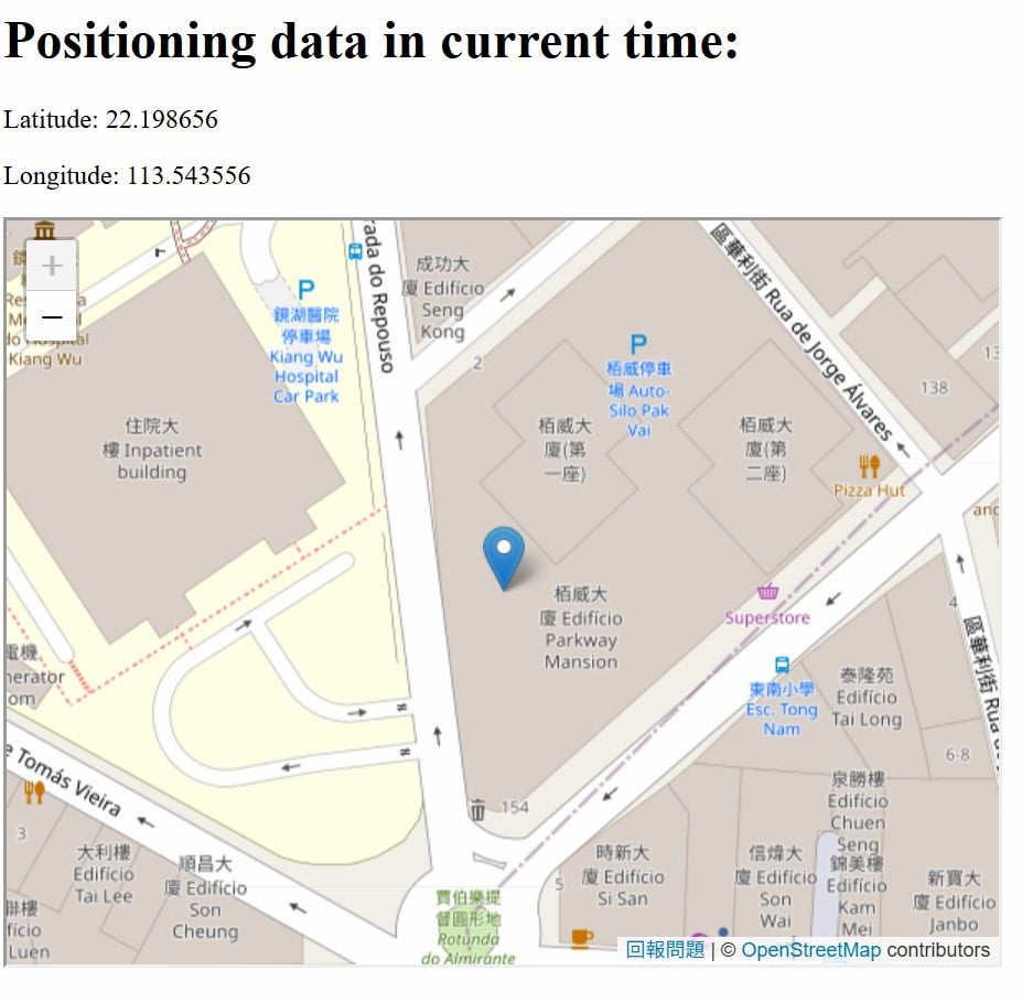
It's a sample that showing the position data in a website which's web server is uploaded in a Microcontroller.
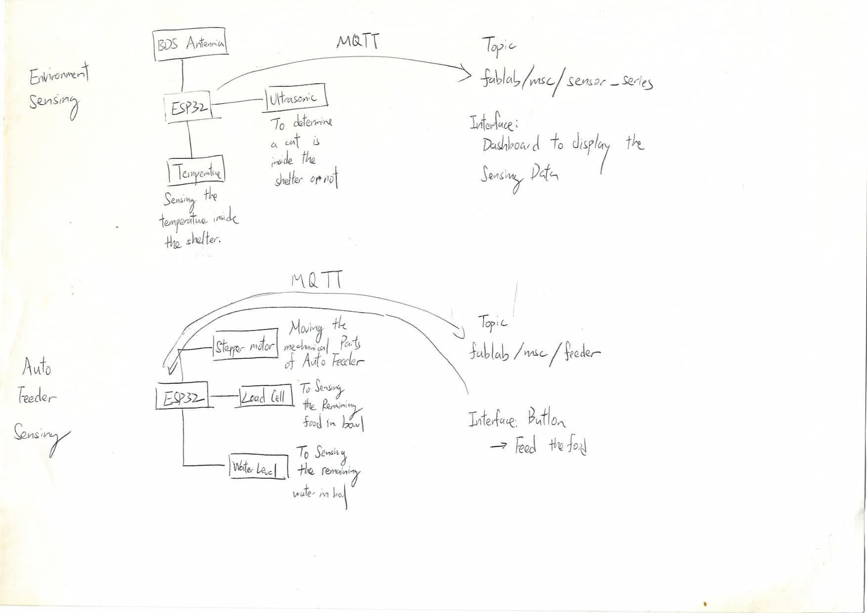
After week14, I'm planning to design the system of final project based on my initial plan. It divided into two parts.
- Environment Sensing
- Auto Feeder
Environment Sensing part is used for sensing the environment data around the cat shelter. The Auto Feeder part is designed for replenishing the food when there's not enough food in the bowl.
After studying week15 - interface, I change the plan that showing the sensing on the website.
Electronic & System Design
Environment sensing Part (Cat Shelter)
The sensing data of environment sensing part is received through MQTT protocol. I can observe the sensing data through MQTTX software.
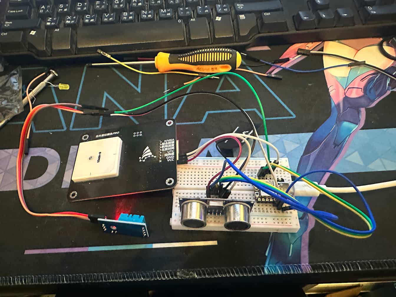
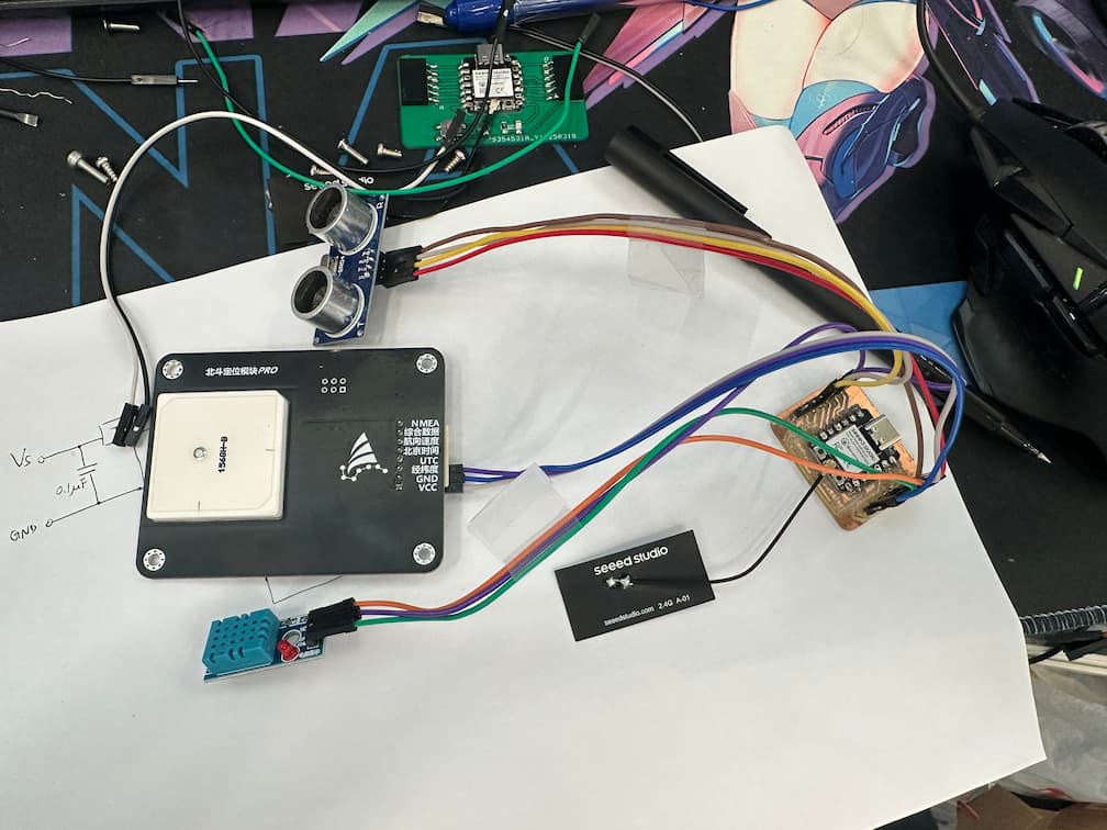
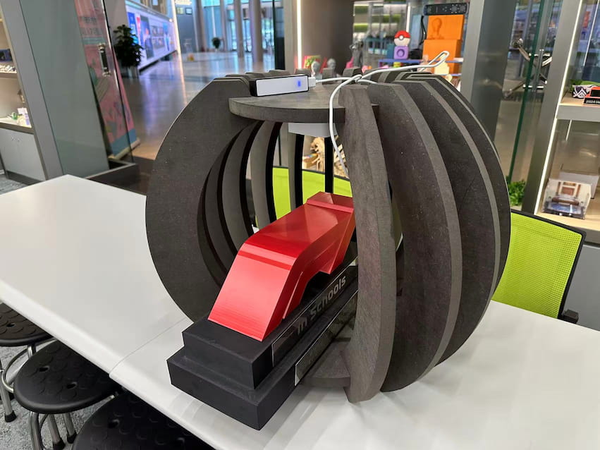
In this part, 1 HC-SR504 ultrasonic sensor, 1 BDS Antennia and 1 DHT11 Sensor are used for sensing the environment.
In order to tidy up the cables of sensors, a smaller PCB is designed and easier to tidy up the cables.
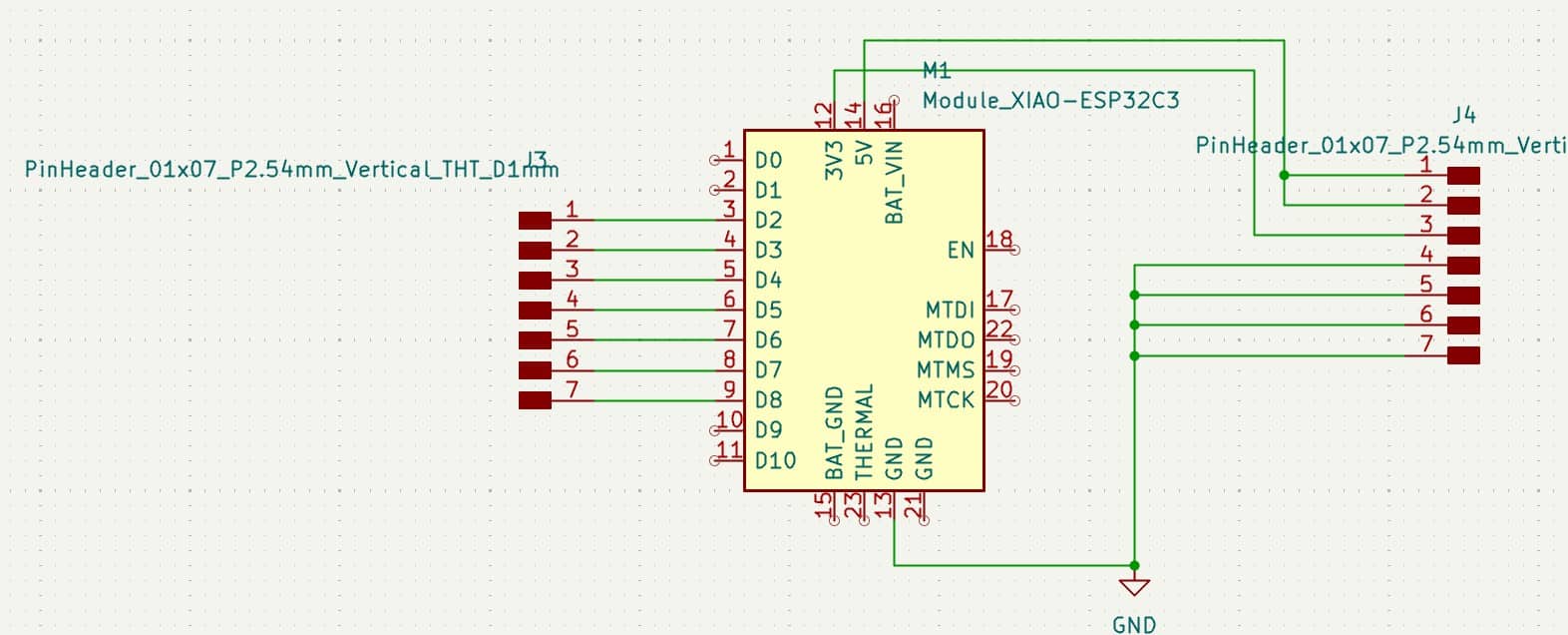
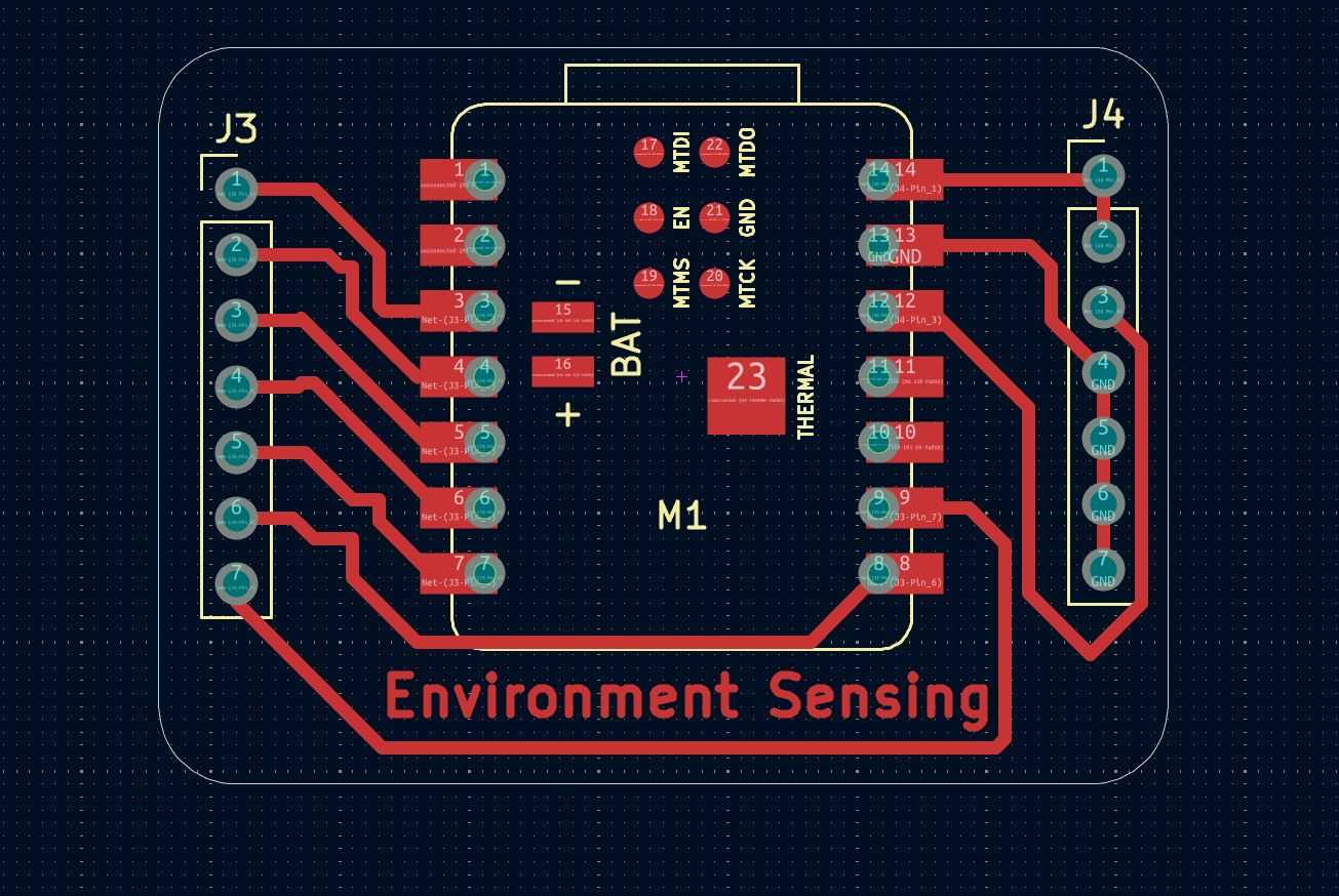

It's simple design: the pins in left hand side are IO pins, the pins in right hand side are power pins.
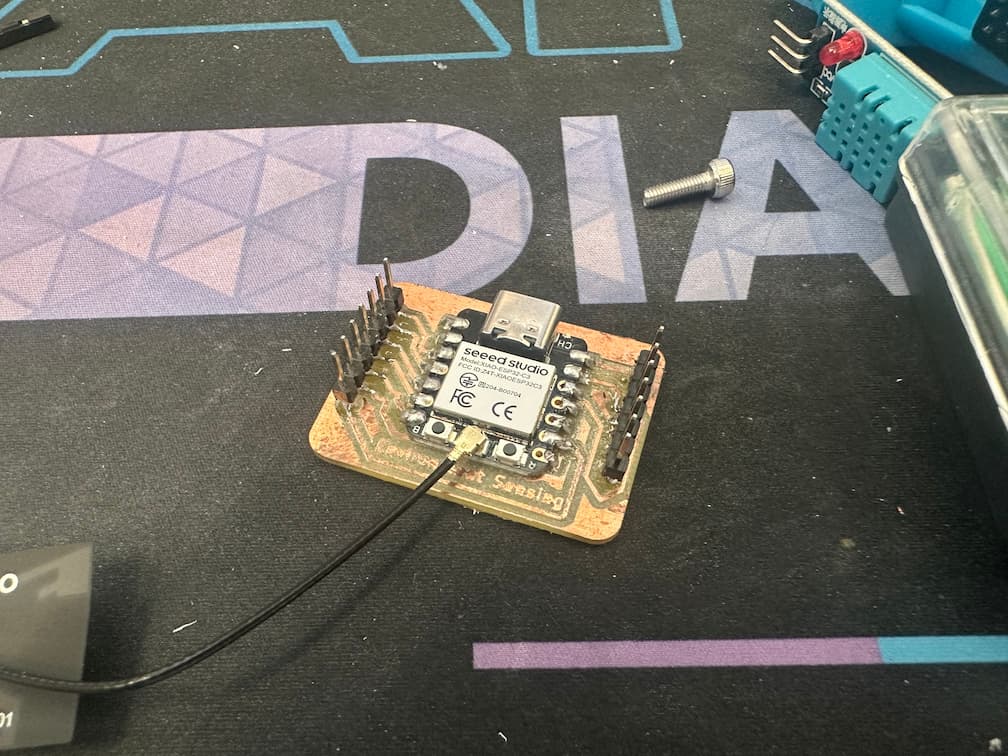
It can be used for tidy up the cables, here's a example:
The code of the environment sensing part is shown as below.
Arduino Code of Environment Sensing Part
#include "DHT.h"
#include <SoftwareSerial.h>
#include <WiFi.h>
#include <PubSubClient.h>

#define DHTPIN D3
#define DHTTYPE DHT11

DHT dht(DHTPIN, DHTTYPE); // constructor to declare our sensor
SoftwareSerial MySerial(D2, D1);

// Pins of sensors
int Echo = D4;
int Trig = D5;
int duration=0, distance=0;
bool cat_state = 0;
String NMEA_BD = "";

// Replace the next variables with your SSID/Password combination - Initial WiFi
const char* ssid = "MSC-Person";
const char* password = "Msc@2333";
// Add your MQTT Broker IP address, example:
//const char* mqtt_server = "192.168.1.144";
const char* mqtt_server = "broker.emqx.io";

WiFiClient espClient;
PubSubClient client(espClient);
unsigned long lastMsg = 0;
#define MSG_BUFFER_SIZE (50)
char msg[MSG_BUFFER_SIZE];
int value = 0;


void setup_wifi() {

  delay(10);
  // We start by connecting to a WiFi networka
  Serial.println();
  Serial.print("Connecting to ");
  Serial.println(ssid);

  WiFi.mode(WIFI_STA);
  WiFi.begin(ssid, password);

  while (WiFi.status() != WL_CONNECTED) {
    delay(500);
    Serial.print(".");
  }

  randomSeed(micros());

  Serial.println("");
  Serial.println("WiFi connected");
  Serial.println("IP address: ");
  Serial.println(WiFi.localIP());
}

// Function of getting MQTT message
void callback(char* topic, byte* payload, unsigned int length) {
  Serial.print("Message arrived [");
  Serial.print(topic);
  Serial.print("] ");
}

void reconnect() {
  // Loop until we're reconnected
  while (!client.connected()) {
    Serial.print("Attempting MQTT connection...");
    // Create a random client ID
    String clientId = "XIAO-ESP32-Client-";
    clientId += String(random(0xffff), HEX);

    if (client.connect(clientId.c_str(), "", "")) {
      Serial.println("connected");
      client.subscribe("fablab/msc/sensor_series");  //subscribe topic
    } else {
      Serial.print("failed, rc=");
      Serial.print(client.state());
      Serial.println(" try again in 5 seconds");
      // Wait 5 seconds before retrying
      delay(5000);
    }
  }
}

void setup() {
  Serial.begin(115200);
  MySerial.begin(9600); //Set 9600 baud rate to get the latitude/longitude information only.
  setup_wifi();
  client.setServer(mqtt_server, 1883);
  client.setCallback(callback);

  pinMode(Trig, OUTPUT);
  pinMode(Echo, INPUT);
  dht.begin();

  #if defined(__AVR_ATtiny85__) && (F_CPU == 16000000)
    clock_prescale_set(clock_div_1);
  #endif
}

void loop() {
  if(!client.connected()){
    reconnect();
  }
  client.loop();

  long now = millis();
  if(now - lastMsg > 1000){
    lastMsg = now;

    digitalWrite(Trig,HIGH);
    delayMicroseconds(10);
    digitalWrite(Trig,LOW);
    duration=pulseIn(Echo,HIGH,4000);
    distance=duration*0.0343/2;
    // If sensing distance from ultrasonic senor < 30cm, turn the cat_state = 1 to represent the cat inside the shelter
    if(distance == 0){
      cat_state = 0;
    }
    else if(distance > 0 && distance <= 30){
      cat_state = 1;
    }

    // If NMEA sentence is read, read each line. Or turn the NMEA_BD variable to "0.0, 0.0"
    if(MySerial.available()!=0){
      NMEA_BD = String(MySerial.readStringUntil('\n'));
    }else{
      NMEA_BD = "0.0, 0.0";
    }
    float t = dht.readTemperature();
    //Send the sensor value through MQTT
    String output_data = String(t) + " " + String(cat_state) + " " + String(NMEA_BD);
    Serial.println(output_data);
    client.publish("fablab/msc/sensor_series", output_data.c_str());
  }
}
The sensing data of environment sensing part is received through MQTT protocol. I can observe the sensing data through MQTTX software.
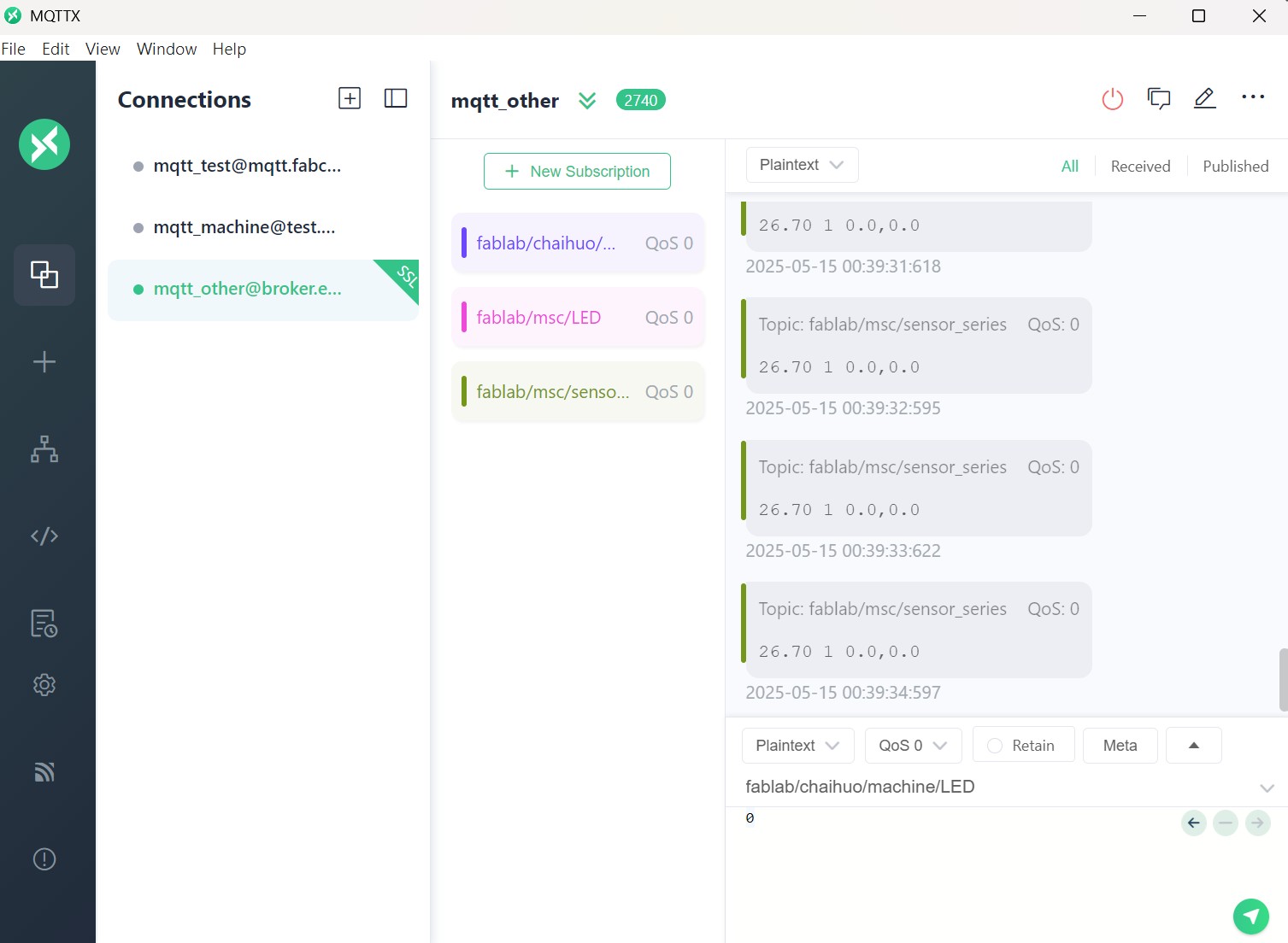
The format of the data sentence is ( temperature cat_state longitude latitude ).
Then, split the data into 4 parts and display on the website.

It may spend lots of time to re-design the UI.
Feeder Part (Auto-Feeder)
The design of Auto-Feeder is shown as below.
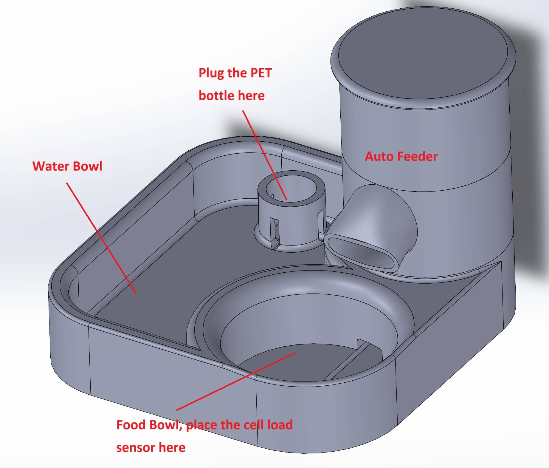
I list some functions of my designed auto-feeder.
- Auto-detect the remain cat food through weight
- Remote feeding (Activate the stepper motor to drive the Archimedes Screw)
- Feed back the water level of the water bowl
The overall circuit structure is shown as below.
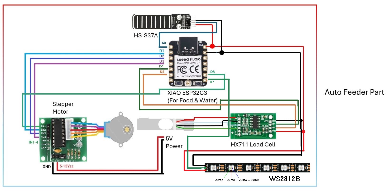
There are 3 parts in auto-feeder system:
- Stepper Motor for remote feeding
- Load Cell for sensing the remain cat cood in the bowl
- Water Level Sensor for sensing water level in water bowl
First, I develop the Remote Feeding Function.
Remote Feeding
I built up the circuit which include XIAO ESP32C3 microcontroller and 28BYJ-48 stepper board with ULN2003 driver board.
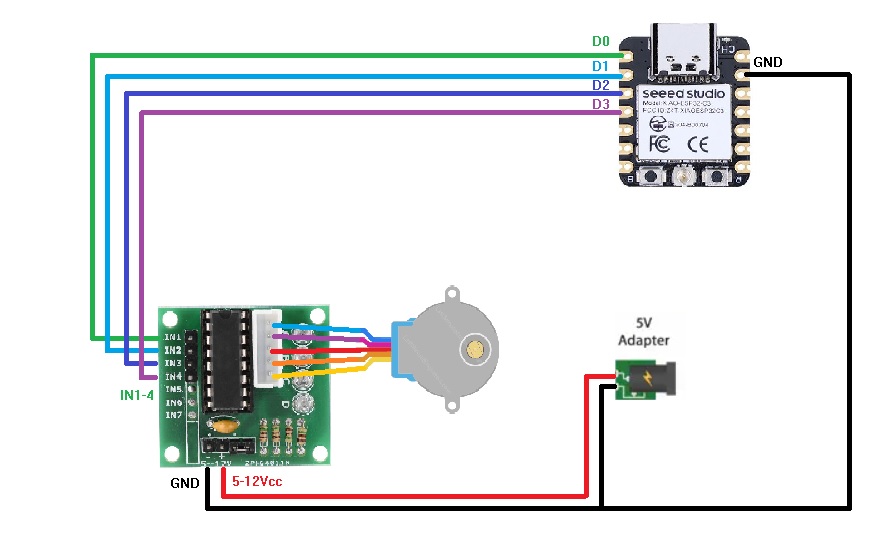
Then, I modify the code as below.
Code for Remote Control Stepper Motor
//Includes the Arduino Stepper Library
#include <Stepper.h>
#include <SoftwareSerial.h>
#include <WiFi.h>
#include <PubSubClient.h>

// Defines the number of steps per rotation
const int stepsPerRevolution = 2038;

// Replace the next variables with your SSID/Password combination - Initial WiFi
const char* ssid = "MSC-Person";
const char* password = "Msc@2333";
// Add your MQTT Broker IP address, example:
const char* mqtt_server = "broker.emqx.io";

WiFiClient espClient;
PubSubClient client(espClient);
unsigned long lastMsg = 0;
#define MSG_BUFFER_SIZE (50)
char msg[MSG_BUFFER_SIZE];
int value = 0;

// Creates an instance of stepper class
// Pins entered in sequence IN1-IN3-IN2-IN4 for proper step sequence
Stepper myStepper = Stepper(stepsPerRevolution, D8, D2, D1, D3);

void setup_wifi() {

  delay(10);
  // We start by connecting to a WiFi networka
  Serial.println();
  Serial.print("Connecting to ");
  Serial.println(ssid);

  WiFi.mode(WIFI_STA);
  WiFi.begin(ssid, password);

  while (WiFi.status() != WL_CONNECTED) {
    delay(500);
    Serial.print(".");
  }

  randomSeed(micros());

  Serial.println("");
  Serial.println("WiFi connected");
  Serial.println("IP address: ");
  Serial.println(WiFi.localIP());
}

// Function of getting MQTT message
void callback(char* topic, byte* payload, unsigned int length) {
  Serial.print("Message arrived [");
  Serial.print(topic);
  Serial.print("] ");

  for (int i = 0; i < length; i++) {
    Serial.print((char)payload[i]);
    Serial.println();
    Serial.print("\n This is length: "+char(length));
  }
  Serial.println();

  //Activate Stepper motor when message '1' received
  if((char)payload[0] == '1'){
      rotate_turn_feeder();
      client.publish("fablab/msc/feeder","0");
  }

}

void reconnect() {
  // Loop until we're reconnected
  while (!client.connected()) {
    Serial.print("Attempting MQTT connection...");
    // Create a random client ID
    String clientId = "XIAO-ESP32-Client-";
    clientId += String(random(0xffff), HEX);

    if (client.connect(clientId.c_str(), "", "")) {
      Serial.println("connected");
      client.subscribe("fablab/msc/feeder");  //subscribe topic
    } else {
      Serial.print("failed, rc=");
      Serial.print(client.state());
      Serial.println(" try again in 5 seconds");
      // Wait 5 seconds before retrying
      delay(5000);
    }
  }
}

void setup() {
  // Nothing to do (Stepper Library sets pins as outputs)
  Serial.begin(115200);
  setup_wifi();
  client.setServer(mqtt_server, 1883);
  client.setCallback(callback);

  #if defined(__AVR_ATtiny85__) && (F_CPU == 16000000)
    clock_prescale_set(clock_div_1);
  #endif
}

void loop() {
  //Connect WiFi
  if(!client.connected()){
    reconnect();
  }
  client.loop();
}

void rotate_turn_feeder(){
  // Rotate CW slowly at 15 RPM
	myStepper.setSpeed(15);
	myStepper.step(stepsPerRevolution);
  myStepper.step(stepsPerRevolution);
  myStepper.step(stepsPerRevolution);
	delay(100);
  //Disable the stepper motor after 1 rev
  digitalWrite(D8, LOW);
  digitalWrite(D1, LOW);
  digitalWrite(D2, LOW);
  digitalWrite(D3, LOW);
}
When '1' is received through MQTT server, the stepper motor will be activated. After 1 revolution, 4 signal pins turn LOW to disable the stepper motor.
I also create a interface in my website
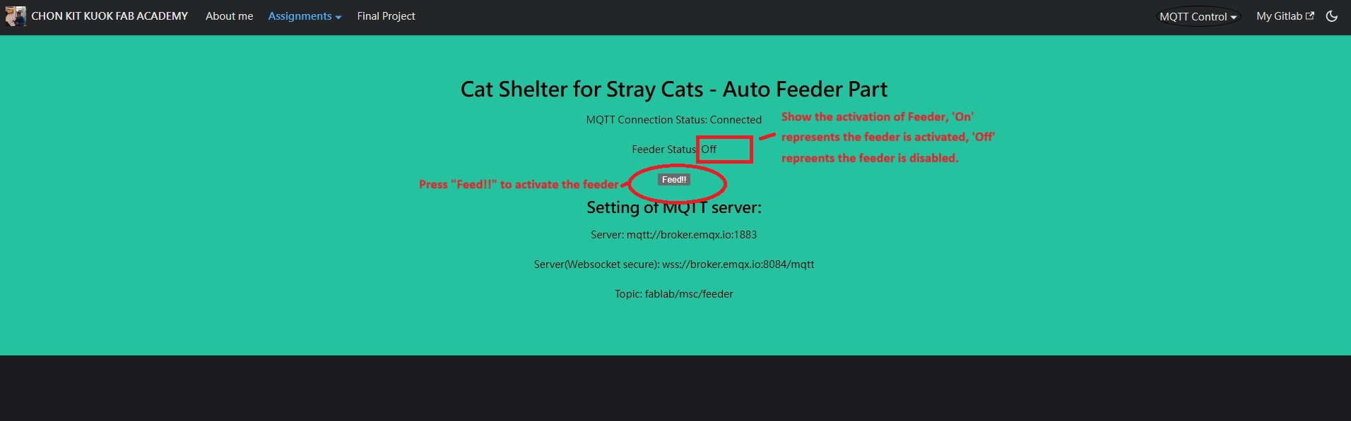
The stepper motor of the feeder will be activated through pressing the button in my website.
Here's the testing video of the stepper motor by remote control.
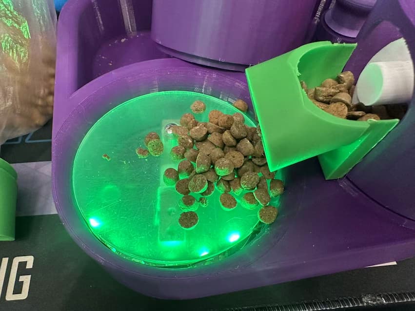
Assemble the stepper motor to the 3D printed parts and test with the cat food.
Cat Food Sensing
Load cell is used for sensing the cat food by weight. It will be placed at the food bowl.
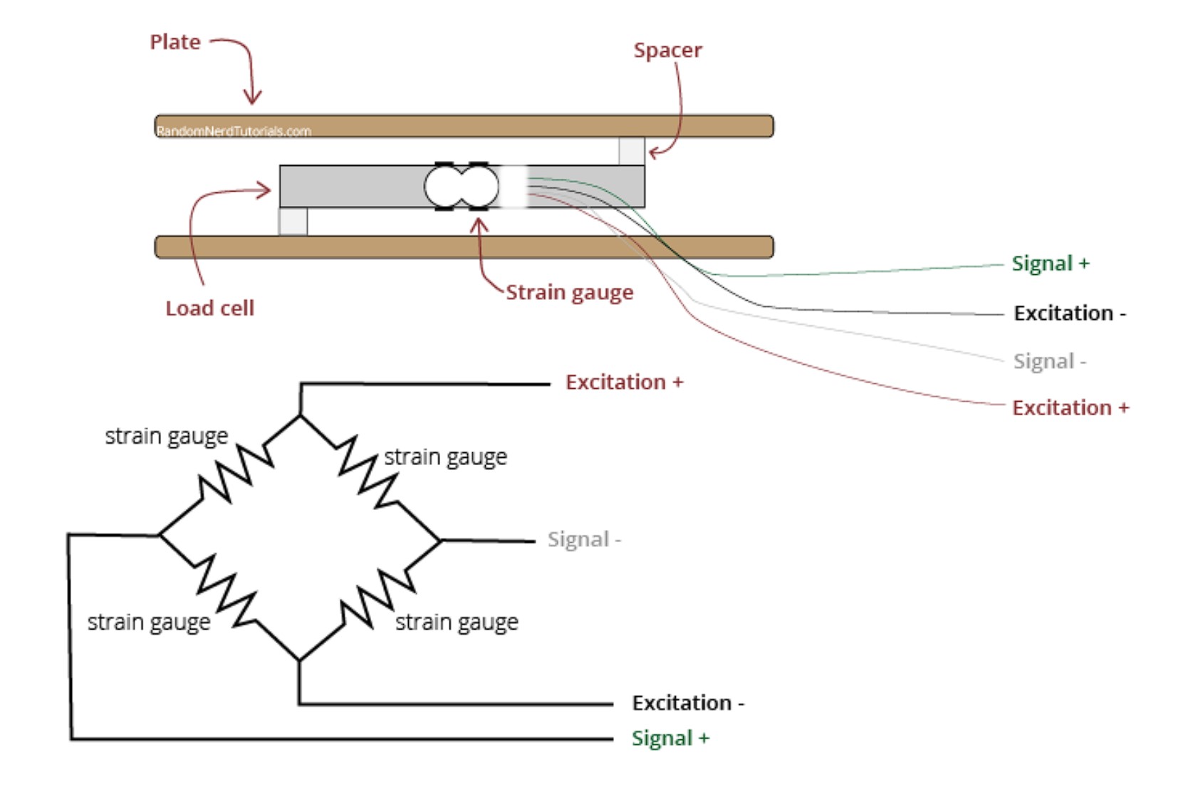
Load cell should be applied with HX711 amplifier which contains 4 wires.
- VCC
- GND
- DT
- SCK
The test code of the HX-711 is shown as below.
Code for Load Cell with HX711
#include <HX711.h>

HX711 scale;
uint8_t dataPin = D4;
uint8_t clockPin = D5;
int32_t offset = 45585;
float_t factor = 188.233414;

void setup() {
    Serial.begin(115200);
    delay(1000);
    Serial.println("Initial HX711");
    scale.begin(dataPin, clockPin);
    scale.set_offset(offset);
    scale.set_scale(factor);
    scale.tare(20);
}

void loop() {
    delay(100);

    if (scale.is_ready()) {
      float avg_units = scale.get_units(10);
      Serial.printf("%f g.\n", avg_units);
    }
}
I have tested a roll of solder wire with weight 49 grams on the load cell. And sensing data shows about 51 grams.
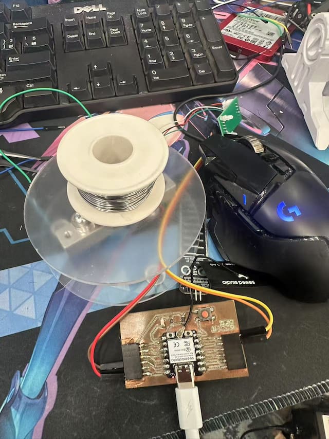
Maybe it needs to be calibrated. But it works for sensing with cat food without calibrating.
Water level sensing
HS-S37A is applied for water level sesning for remain water in the water bowl.
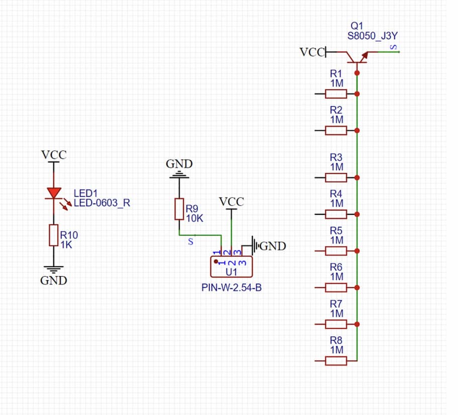
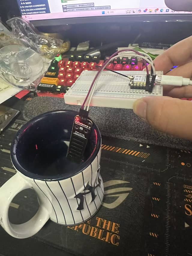
The resistance of resistors which is connected to the base bin of transistor will be changed when the water level changed. It case the output voltage changed.
The sensor is tested by placing it into a mug to measure the water level.
Here's the code of the HS-S37A sensor.
Code for testing HS-S37A
volatile float num;
volatile int Buzzer;

void setup(){
  num = 0.0;
  Serial.begin(9600);
  //Connect the sensor to A0 pin and set us input for analogRead.
  pinMode(A0, INPUT);
}

void loop(){
  //When water level is deeper, higher voltage sensed.
  num = long(analogRead(A0));
  Serial.println(num);
  delay(500);
}
WS2812b LED
WS2812b is used for display the status by light. It is placed beside the load cell and display different color to indicate the state of auto-feeder.
For example, after pressing Feed!! button in the website, WS2812b is designed to display red light.
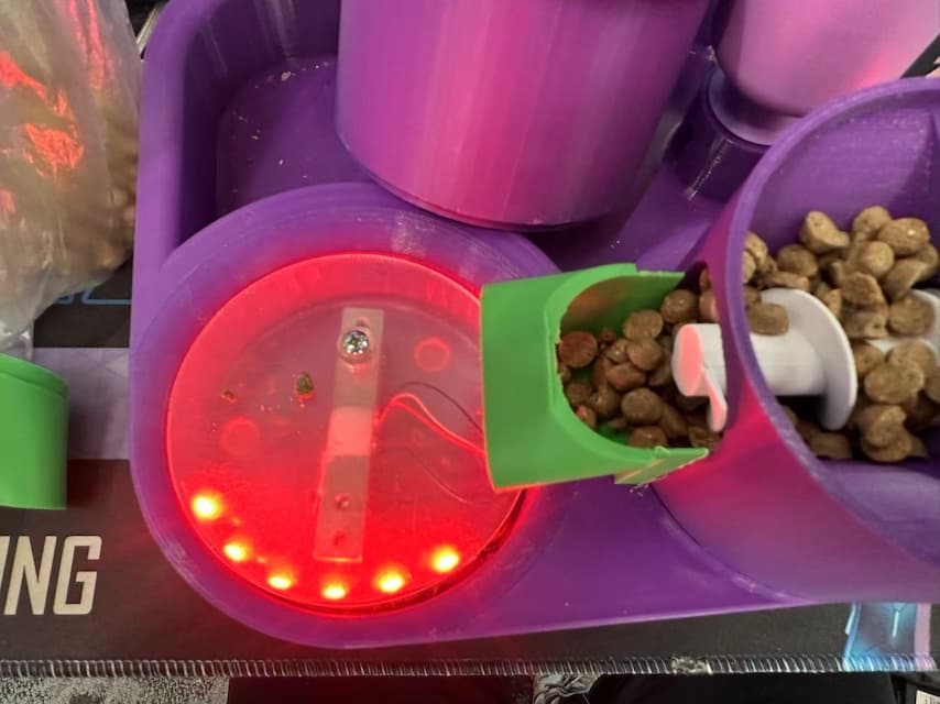
During the feeding step, yellow light will be turned on to display the stepper motor is operating.
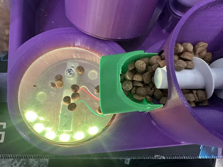
Green light wll be turned on to display the feeding step is over.
Here the code explaination:
Define and import the libraries
#define NUMPIXELS 60 // Popular NeoPixel ring size
Adafruit_NeoPixel pixels(NUMPIXELS, D7, NEO_GRB + NEO_KHZ800);
#define DELAYVAL 20 // Time (in milliseconds) to pause between pixels
Turn off all the LED
pixels.clear(); // Set all pixel colors to 'off'
pixels.show();   // Send the updated pixel colors to the hardware.
Turn on the Green LED.
for(int i=0; i<NUMPIXELS; i++) { // For each pixel...
    // Here we're using a moderately bright green color:
    pixels.setPixelColor(i, pixels.Color(0, 255, 0));
    pixels.show();   // Send the updated pixel colors to the hardware.
    delay(DELAYVAL); // Pause before next pass through loop
}
If I want to modify the display color of LED, modify the parameters in pixels.Color(). There are 3 parameters which represents 0-255 values of RED, GREEN and BLUE, respectively.
Integration
The sensing data of the feeder will be integrated in the same website to monitor the remain food and water in the feeder.

The firmware of the feeder is shown as below.
Firmware of Auto-Feeder
//Includes the Arduino Stepper Library
#include <Stepper.h>
#include <SoftwareSerial.h>
#include <WiFi.h>
#include <PubSubClient.h>
#include <HX711.h>
#include <Adafruit_NeoPixel.h>
#ifdef __AVR__
 #include <avr/power.h> // Required for 16 MHz Adafruit Trinket
#endif

#define NUMPIXELS 60 // Popular NeoPixel ring size
Adafruit_NeoPixel pixels(NUMPIXELS, D7, NEO_GRB + NEO_KHZ800);
#define DELAYVAL 20 // Time (in milliseconds) to pause between pixels

//define HS-S37A
volatile float water_num;
volatile int Buzzer;

//define HX711
HX711 scale;
uint8_t dataPin = D4;
uint8_t clockPin = D5;
int32_t offset = 45585;
float_t factor = 188.233414;

// Defines the number of steps per rotation
const int stepsPerRevolution = 2038;

// Replace the next variables with your SSID/Password combination - Initial WiFi
const char* ssid = "MSC-Person";
const char* password = "Msc@2333";
// Add your MQTT Broker IP address, example:
const char* mqtt_server = "broker.emqx.io";

WiFiClient espClient;
PubSubClient client(espClient);
unsigned long lastMsg = 0;
#define MSG_BUFFER_SIZE (50)
char msg[MSG_BUFFER_SIZE];
int value = 0;

//Define feed_work_status
bool feed_work_status = 0;

// Creates an instance of stepper class
// Pins entered in sequence IN1-IN3-IN2-IN4 for proper step sequence
Stepper myStepper = Stepper(stepsPerRevolution, D8, D2, D1, D3);

void setup_wifi() {

  delay(10);
  // We start by connecting to a WiFi networka
  Serial.println();
  Serial.print("Connecting to ");
  Serial.println(ssid);

  WiFi.mode(WIFI_STA);
  WiFi.begin(ssid, password);

  while (WiFi.status() != WL_CONNECTED) {
    delay(500);
    Serial.print(".");
  }

  randomSeed(micros());

  Serial.println("");
  Serial.println("WiFi connected");
  Serial.println("IP address: ");
  Serial.println(WiFi.localIP());
}

// Function of getting MQTT message
void callback(char* topic, byte* payload, unsigned int length) {

  Serial.print("Message arrived [");
  Serial.print(topic);
  Serial.print("] ");
/*
  for (int i = 0; i < length; i++) {
    Serial.print((char)payload[i]);
    Serial.println();
    Serial.print("\n This is length: "+char(length));
  }
*/
  Serial.println();

  //Activate Stepper motor when message '1' received
  if((char)payload[0] == '1'){
      feed_work_status = 1;
      neopixel_go_1();
      rotate_turn_feeder();
      client.publish("fablab/msc/feeder","0");
      feed_work_status = 0;
      neopixel_go_2();
  }

}

void reconnect() {
  // Loop until we're reconnected
  while (!client.connected()) {
    Serial.print("Attempting MQTT connection...");
    // Create a random client ID
    String clientId = "XIAO-ESP32-Client-";
    clientId += String(random(0xffff), HEX);

    if (client.connect(clientId.c_str(), "", "")) {
      Serial.println("connected");
      client.subscribe("fablab/msc/feeder");  //subscribe topic
    } else {
      Serial.print("failed, rc=");
      Serial.print(client.state());
      Serial.println(" try again in 5 seconds");
      // Wait 5 seconds before retrying
      delay(5000);
    }
  }
}

void setup() {
  // Nothing to do (Stepper Library sets pins as outputs)
  Serial.begin(115200);

  Serial.println("Initial HX711");
  scale.begin(dataPin, clockPin);
  scale.set_offset(offset);
  scale.set_scale(factor);
  scale.tare(20);
  setup_wifi();
  client.setServer(mqtt_server, 1883);
  client.setCallback(callback);

  #if defined(__AVR_ATtiny85__) && (F_CPU == 16000000)
    clock_prescale_set(clock_div_1);
  #endif

  //HSS37A initial
  water_num = 0.0;
  Buzzer = 9;
  pinMode(A0, INPUT);
  pixels.clear(); // Set all pixel colors to 'off'
  pixels.show();   // Send the updated pixel colors to the hardware.
}

void loop() {
  //Connect WiFi
  if(!client.connected()){
    reconnect();
  }
  client.loop();

  if (scale.is_ready() && feed_work_status==0) {
      float avg_units = scale.get_units(10);
      //Serial.printf("%f g.\n", avg_units);
      water_num = long(analogRead(A0));
      //Serial.println(water_num);
      String output_mqtt = String("sensor") + "," + String(avg_units) + "," + String(water_num);
      //Serial.println(output_mqtt);
      client.publish("fablab/msc/feeder", output_mqtt.c_str());
  }
}

void neopixel_go_1(){
  for(int j = 0; j < 2; j++){
    for(int i=0; i<NUMPIXELS; i++) { // For each pixel...
        // pixels.Color() takes RGB values, from 0,0,0 up to 255,255,255
        // Here we're using a moderately bright green color:
        pixels.setPixelColor(i, pixels.Color(255, 0, 0));
        pixels.show();   // Send the updated pixel colors to the hardware.
        delay(DELAYVAL); // Pause before next pass through loop
    }
    pixels.clear(); // Set all pixel colors to 'off'
    pixels.show();   // Send the updated pixel colors to the hardware.
    delay(1000);
  }
}

void neopixel_go_2(){
    for(int i=0; i<NUMPIXELS; i++) { // For each pixel...
        // pixels.Color() takes RGB values, from 0,0,0 up to 255,255,255
        // Here we're using a moderately bright green color:
        pixels.setPixelColor(i, pixels.Color(0, 255, 0));
        pixels.show();   // Send the updated pixel colors to the hardware.
        delay(DELAYVAL); // Pause before next pass through loop
    }
    delay(5000);
    pixels.clear(); // Set all pixel colors to 'off'
    pixels.show();   // Send the updated pixel colors to the hardware.
}

void rotate_turn_feeder(){
  // Rotate CW slowly at 15 RPM
  for(int i=0; i<NUMPIXELS; i++) { // For each pixel...
        // pixels.Color() takes RGB values, from 0,0,0 up to 255,255,255
        // Here we're using a moderately bright green color:
        pixels.setPixelColor(i, pixels.Color(255, 255, 0));
        pixels.show();   // Send the updated pixel colors to the hardware.
        delay(DELAYVAL); // Pause before next pass through loop
  }
	myStepper.setSpeed(10);
  myStepper.step(-stepsPerRevolution/5);
	myStepper.step(stepsPerRevolution);
  myStepper.step(stepsPerRevolution*2);
  myStepper.step(-stepsPerRevolution/5);
	myStepper.step(stepsPerRevolution);
  myStepper.step(stepsPerRevolution*2);
  myStepper.step(-stepsPerRevolution/5);
	delay(100);
  //Disable the stepper motor after 1 rev
  digitalWrite(D8, LOW);
  digitalWrite(D1, LOW);
  digitalWrite(D2, LOW);
  digitalWrite(D3, LOW);
}
In order to tidy up the cables and planning to input the power by power source. A PCB is designed.
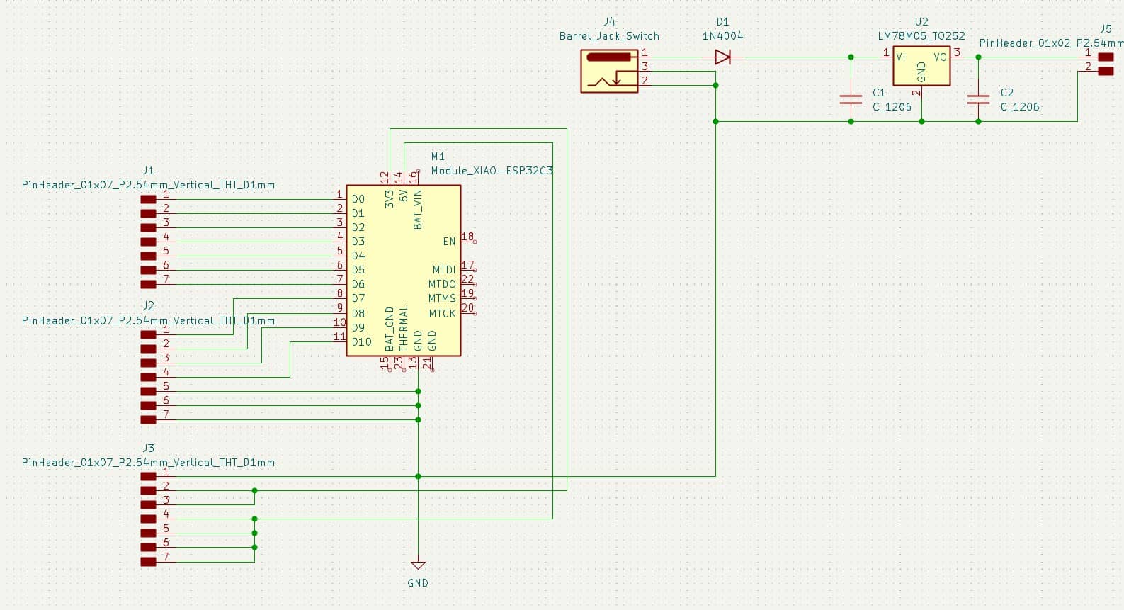
A LM78M05 is designed for turn down the voltage of the power source to 5V for stepper motor.
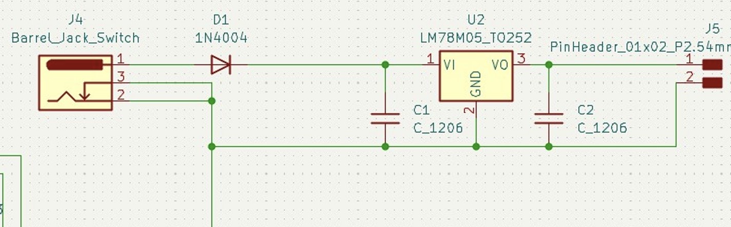
The internal power source of XIAO ESP32C3 also can drive the stepper motor, but torque is not enough. Voltage Regulator circuit is designed for driving the actuator by power source. It also can provide the power to Microcontroller.
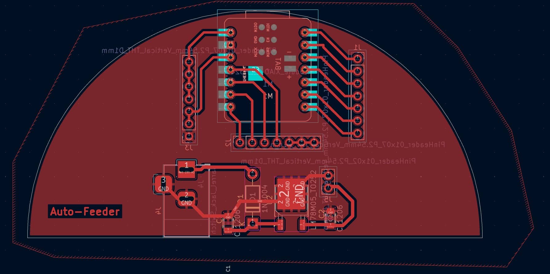
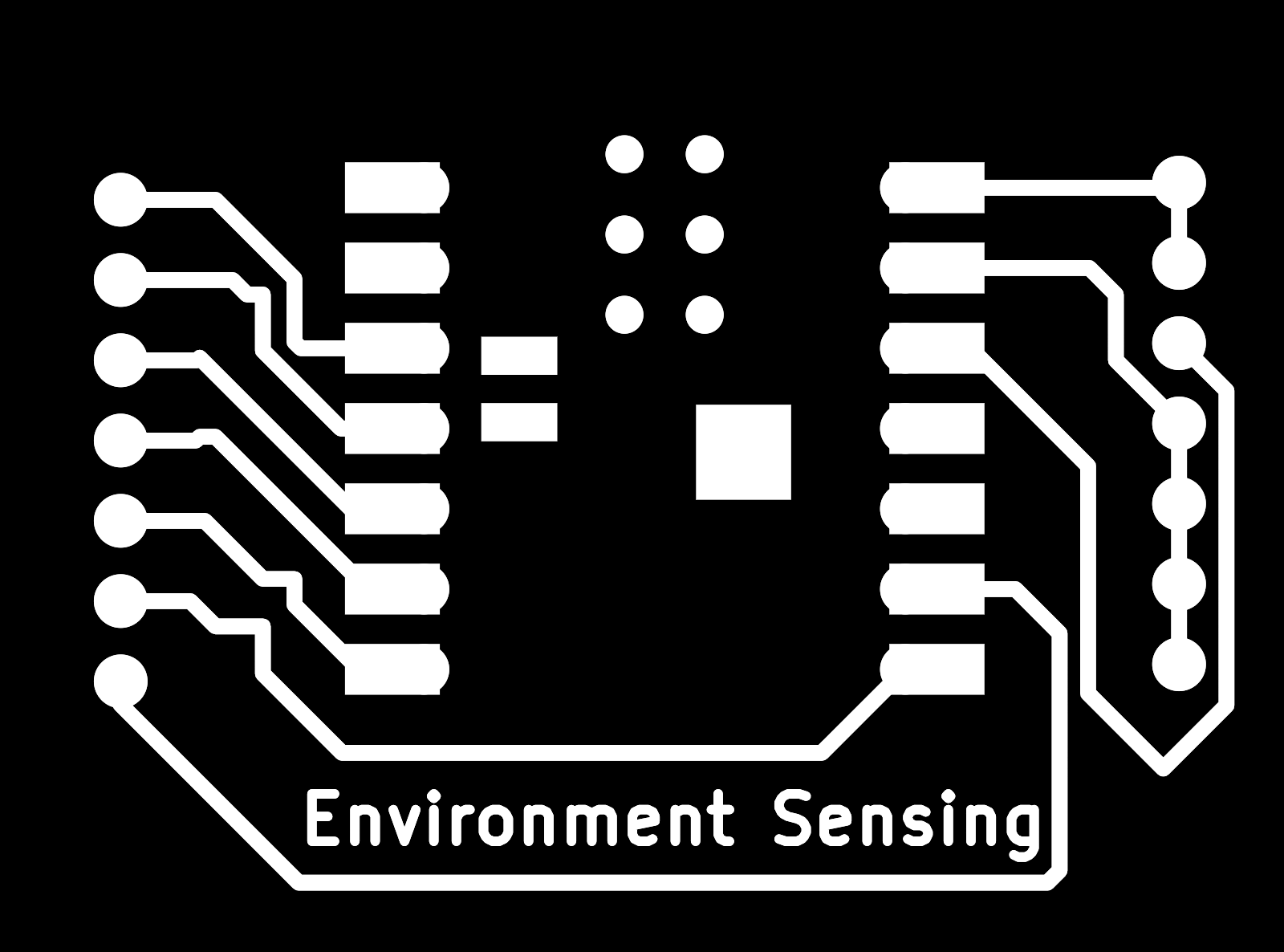
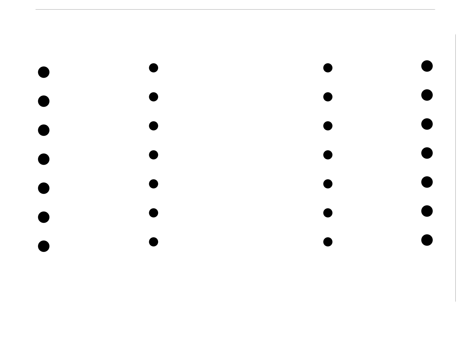
Here's the output image generated by Gerber2png for generating G-code by modsproject.
- Tracing Image
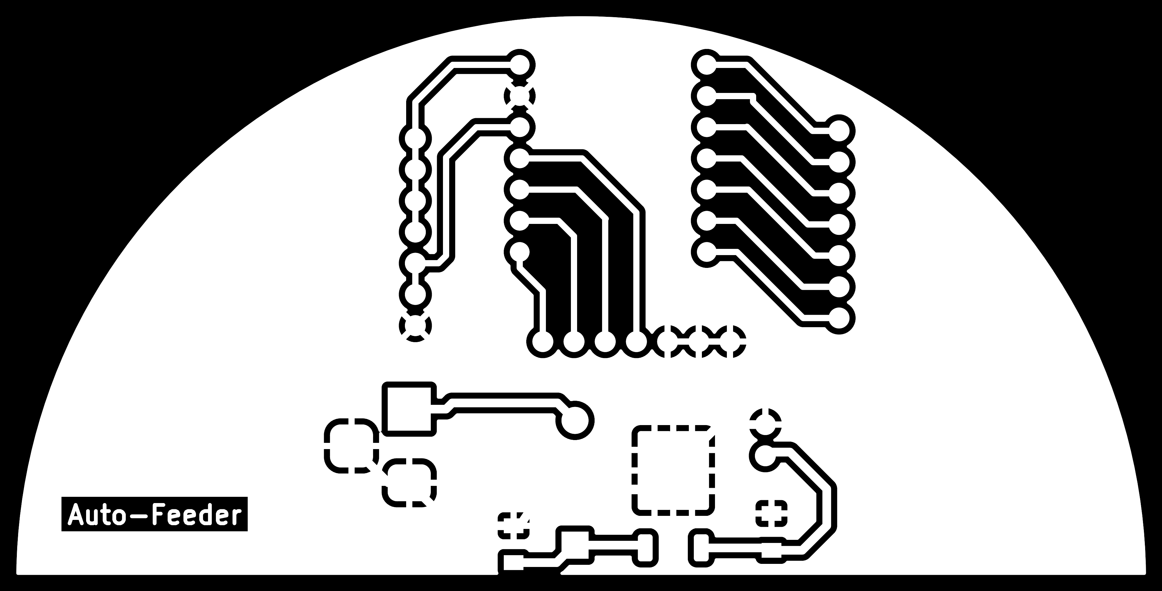
- Drilling Image

- Outline Image

The 3D simulation:
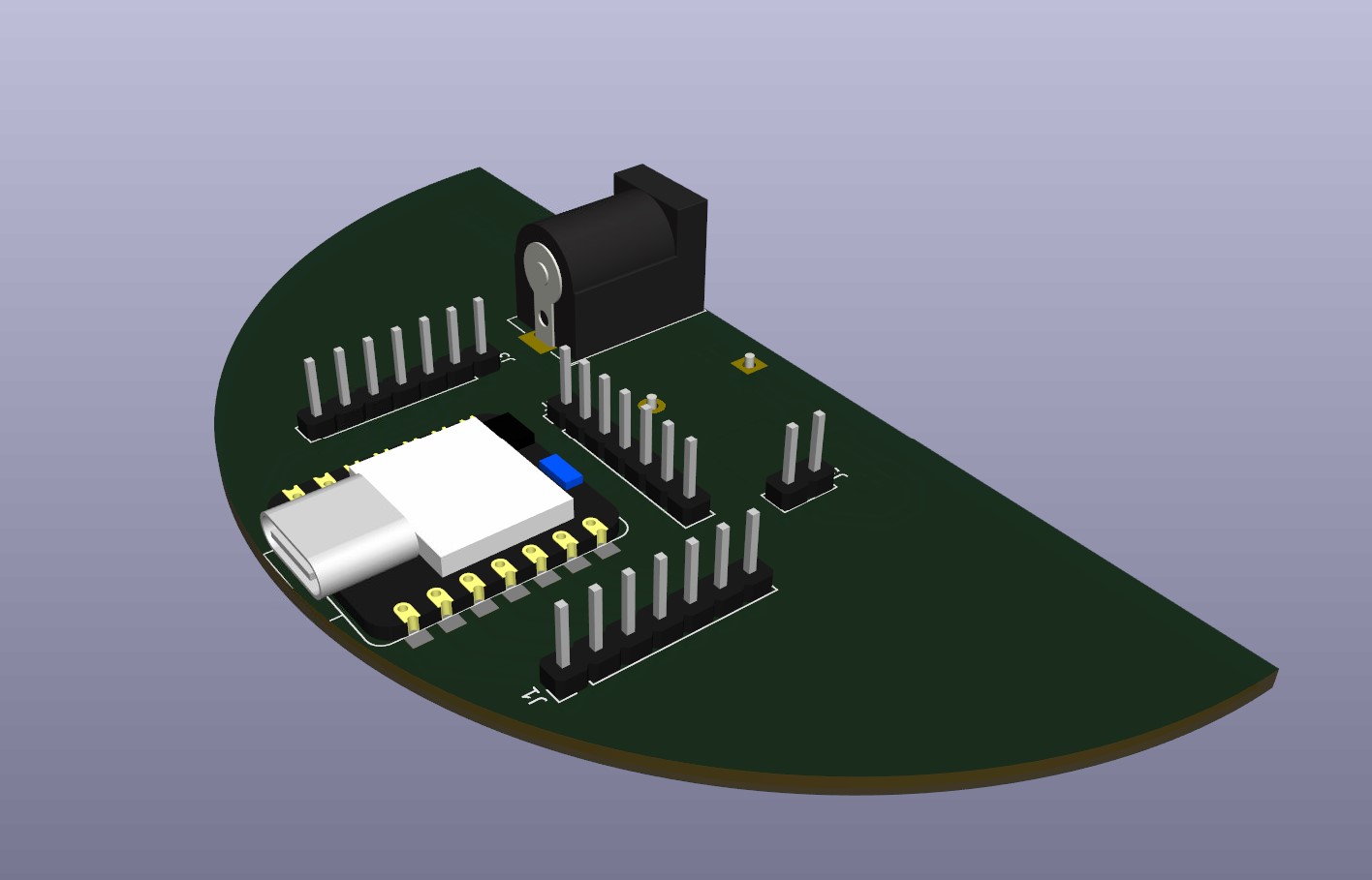
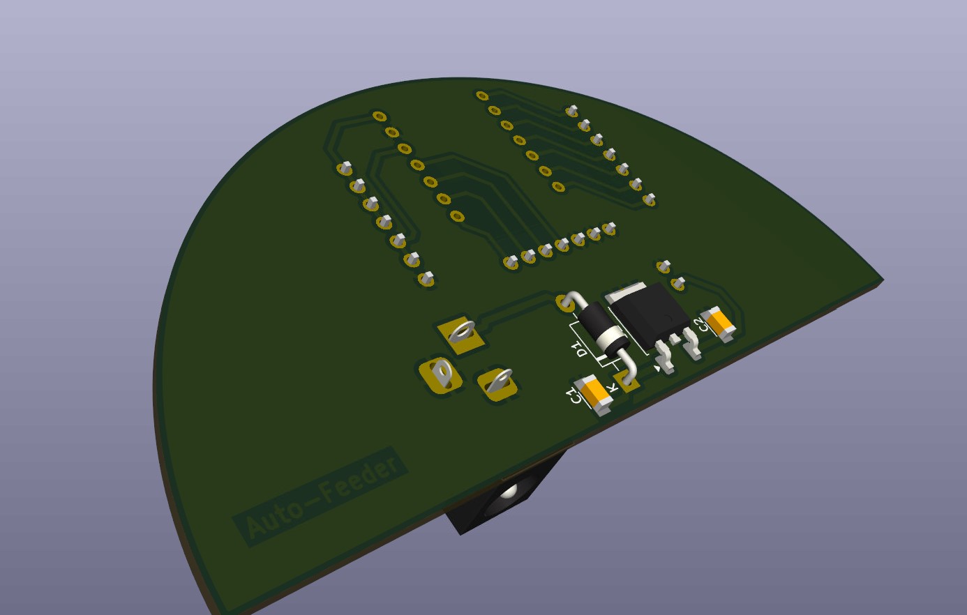
This pcb is designed in semi-circle shape for placing it into the circuit board chamber.
Interface
There are 2 webpages to receive the sensing data or control the auto-feeder.
Environment Sensing
In this interface, there are 3 input devices installed.
- BDS Antennia
- DHT11 Sensor
- Ultrasonic Sensor
I also put a trophy into the shelter to simulate there's a cat in the shelter.
Cat state will display 1 to indicate there's a cat inside the shelter. The position information will be displayed in the map. And the temperature information is also displayed.
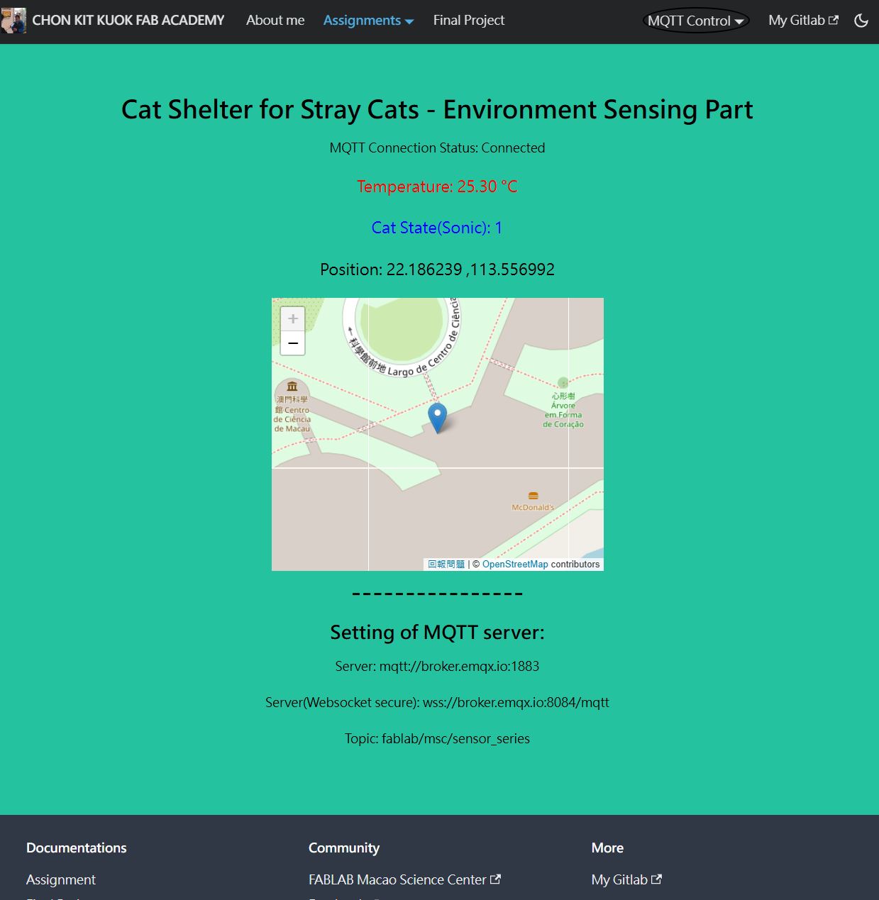
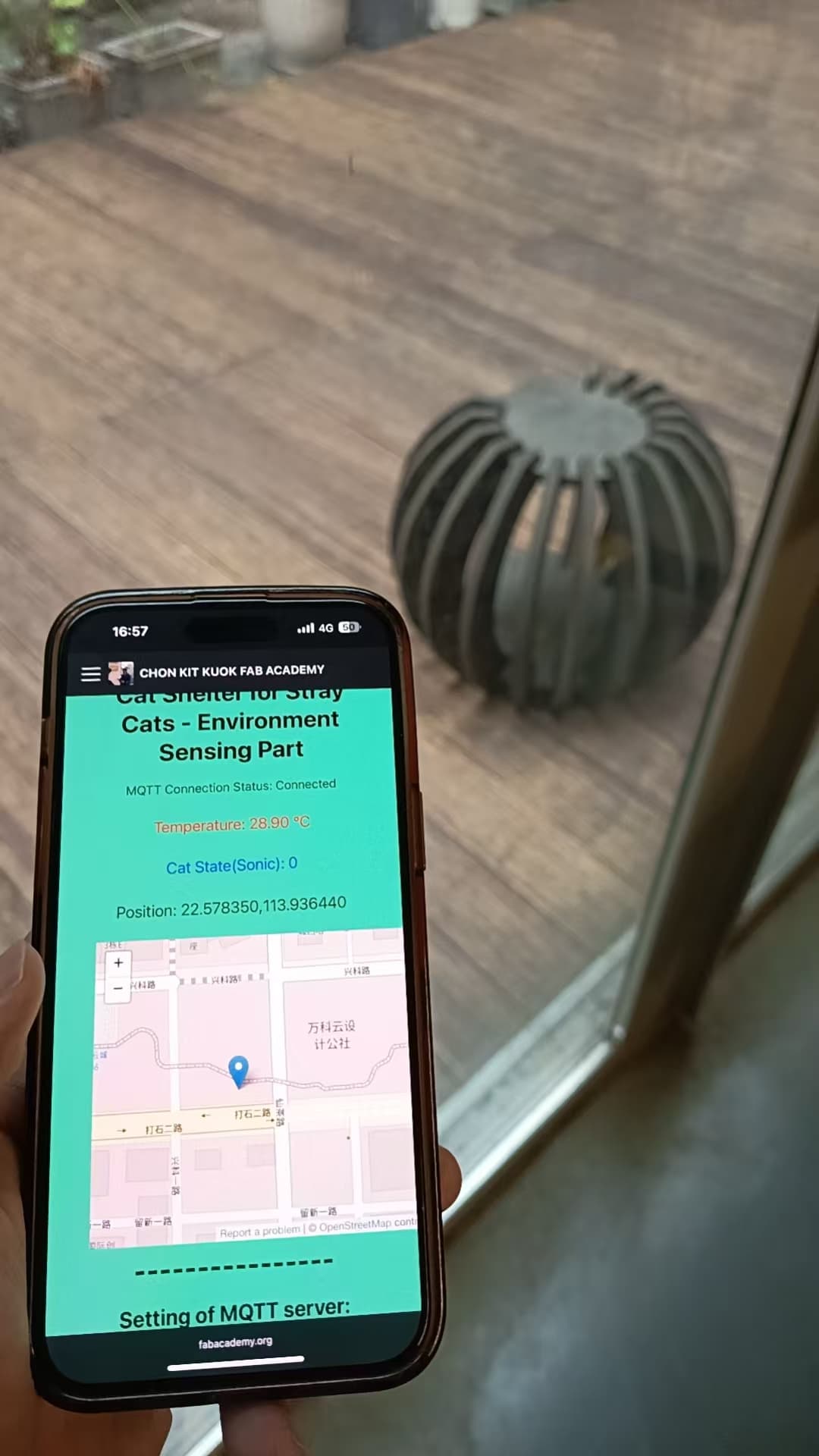
The designed interface is also available in mobile version.
Auto-Feeder
There are 2 input devices and 2 output devices in auto-feeder.
Input Devices:
- Water Level Sensor
- Load Cell Sensor
Output Devices:
- Stepper Motor
- WS2812B LED
The information of input devices are shown in the webpage and the work state of feeder is shown as On or Off.
It's also available in mobile version.