12.Input devices
I already stated the difference between what's consideredd an output and and input, but for us to remember, an input is a module or component that can read any external information for the microcontroller to interprete. These inputs can include various forms of data signals, control signals, or power supply inputs that the PCB needs to function correctly.
There are different types of inputs : Analogs and Digital:Digital Inputs:
- The Digital inputs are signals that exist in one of two states: on or off (1 or 0). They are used in electronic systems to represent binary information and are less susceptible to noise and signal degradation.
Examples:
- Push buttons: Used in various electronic devices to start or stop a function.
- Switches: Such as on/off switches in household appliances.
- Digital sensors: Sensors that provide a binary output, like a motion detector that signals presence or absence.
Analog Inputs:
- Temperature sensors: Like thermistors or thermocouples that measure temperature and provide a continuous voltage or current output.
- Microphones: Convert sound waves into analog electrical signals.
- Light sensors: Such as photodiodes, which generate a varying electrical signal based on the intensity of light.
Examples:
- The Analog inputs are continuous signals that can take on any value within a given range. These inputs represent varying physical quantities, such as temperature, sound, or light, and require analog-to-digital conversion for processing in digital systems.
In our group assignment we learnt how to connect one and provide information, comparing with data from the environment. If you wish to check it out, our documentation is Here .
Which Inputs did I use?
For this assignment I chose to test two different inputs: A joystick and a photoresistor. Even so, during week 6 I tested a microphone, before understanding that it was an input. You may check it out Here . I didn't provide much data of it, then so I will include it here too.
>| Input | Description | Picture |
|---|---|---|
| Joystick | A joystick is an input device consisting of a stick that pivots on a base and reports its angle or direction to the device it is controlling. It is commonly used in video games and control systems to allow users to navigate and interact with digital environments. The joystick typically includes buttons for additional functions and can provide analog input by detecting the stick's position on two or more axes. | 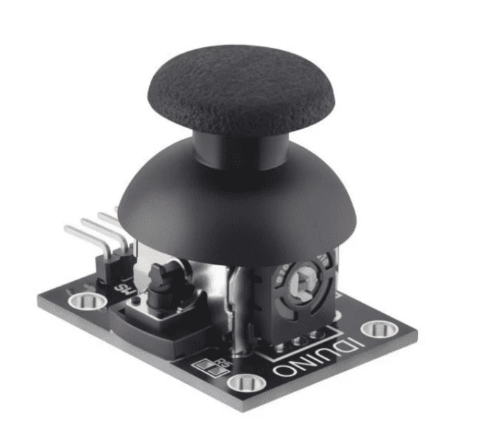 |
| Photoreistor | A photoresistor, also known as a light-dependent resistor (LDR), is a type of resistor whose resistance decreases as the intensity of light falling on it increases. It is used in circuits to sense the presence and intensity of light, making it a crucial component in light-sensing devices. Photoresistors are commonly found in applications such as automatic lighting control, light meters, and alarm systems. (Picture from Steren) | 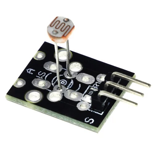 |
| Microphone- Sound sensor | A microphone module is an electronic device that captures sound waves and converts them into electrical signals for processing. It typically includes a microphone element, amplification circuitry, and sometimes an analog-to-digital converter. The captured sound signals can be processed by other devices or software for further use in audio-related tasks. | 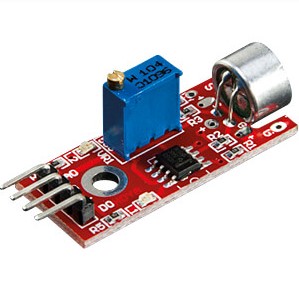 |
Important:
For this week I used three boards:a) The Joystick+ LED
-
The first thing you must know about Joysticks is that they're modules used to control
movements in electronic projects. It typically consists of two potentiometers for X and Y
axes and a push-button. During this week I used it to control different reactions on some
outputs.

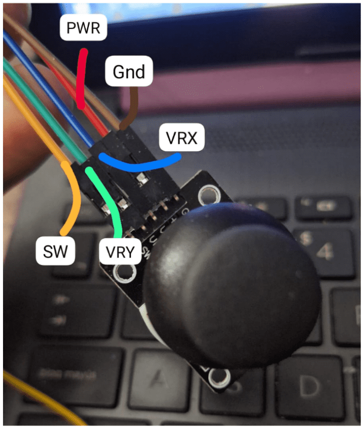
- The first thing I did with it was to check the wiring and recognize it's pins. It has one
for Ground , one for Power , one to control the X axis called VRX
and its equivalent for the Y axis VRY . This also comes with a Switch that might
be optional to press and it's called SW .
-
As I wired, I reviewed the pins I had on the board I would use first, I used my ESP32A3
from
week 8 since that's the one that has the most leds and I wanted to try first
a code to turn on and
off each depending on the direction of the joystick. To connect it, I looked for analog pins
for the VRX and VY and a digital one for SW.
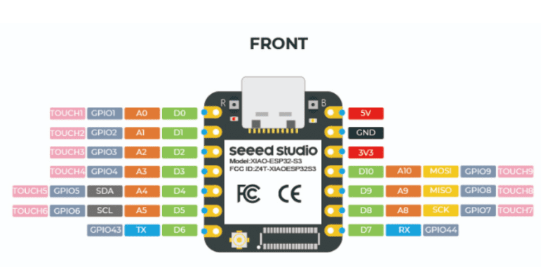
-
Once I Knew where I had to put everything, I connected the wires and plugged the board to my
computer. There, I started the code.
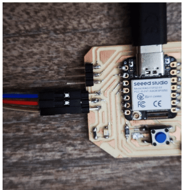
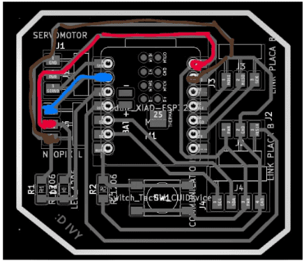
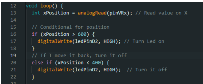
- First I had to define what I was going to work with: I used only the movement on X as the input, so this was on pin D1. And the output was my LED, which was on D2.

- Then I defined the conditional for my code. I wanted the led to shine more everytime the joystick moved outside the middle, so first I had to set a variable for it. There I needed to create a variable for the position.

- Now, I used the conditional if and chose 400 and 600 in the code as thresholds to detect significant movements of the joystick. These values represent points where the joystick's analog readings indicate noticeable shifts in position, distinguishing them from less significant changes. So, whenever I moved outside the main position to the right it would turn on, otherwise the conditional else turned it off (at least lower the brightness because this is a very bright LED).
- Here it is how it looks! I only had to move the joystick to the a little to get a reaction.
a) The Joystick + Servo
-
Now, I wanted also to test the reactions I could get on my Servo and if I could move it
with
it to the sides on the X axis. As in week 9, I kept the same specifications to set the
servo:
- Make sure the library works with your microcontroller, in my case the ESP32s3 needed a different library for the servo than the one in arduino, this is called literally ESP32 Servo. There is a link to add it here
- Once you have it, tell the code you will use the ESP32 servo under the include command
- Next, define the location of the pins for the variables
- Then tell the code which object youll use from the library. This is a “Servo”, so I wrote it and gave it a name
- Then link the pin of the variable to the object you created and will be using

- Once I did the last steps, It was time to code the loop. As in the previous experiment with the joystick, I had to instruct the program to analogRead , which meant to interprete the signal of the joystick. Then define another variable for the degrees the servo would rotate its arm (considering its max is about 180°). Then I used another function called map that would adapt the rank of values from the input to the degrees the output could move.

- Finally, I used the function write to move the servo to the position the angle I wanted, depending on the joystick's movements.

- This is how it reacted, I had to take advantage of the delay function since the joystick comes back to it's original position once you stop pushing, so that the movement could have less kickback.
a) The Joystick + Neopixels
Now, for the third test I used another board that has Neopixels . The idea was to change color as the joystick moves in circles.
- First, I included the Adafruit_NeoPixel library and defined constants for the
number
of NeoPixels and the pins where the NeoPixels and joystick were
connected.

- Then, I set up the Adafruit_NeoPixel object and created an array with the
rainbow
colors
I wanted to use. I also initialized variables to keep track of the current color
index
and the previous angles of the joystick.
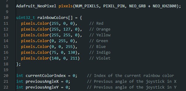
- Next, In the setup function, I initialized the NeoPixel object and set the
brightness to 50%. I also configured the joystick pins as input with
internal
pull-up resistors to get accurate readings.

- In the loop function, I read the analog values from the joystick's
X
and
Y axes and converted these values into angles ranging from 0 to 360
degrees. I
then checked if the joystick's movement was significant, defined as a change
greater
than
10 degrees.

- Now, If the movement was significant, I calculated the current color index
based on the average angle of both axes and updated the previous angle values for
the
next comparison.

- Finally, I updated each NeoPixel with the color corresponding to the
current color index, displayed the updated colors, and added a small
delay
for stability.

- This is the final result of this, it was really fun.
b) The Fotoresistor input for a LED
- A photoresistor, or light-dependent resistor (LDR), is an electronic
component that changes its resistance based on light intensity. It consists of a
semiconductor material , placed between two electrodes. The module typically includes
the LDR and a resistor to form a voltage divider circuit, usually of 10K Ohms. (Image
and data from here).
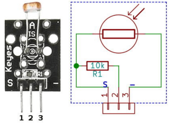
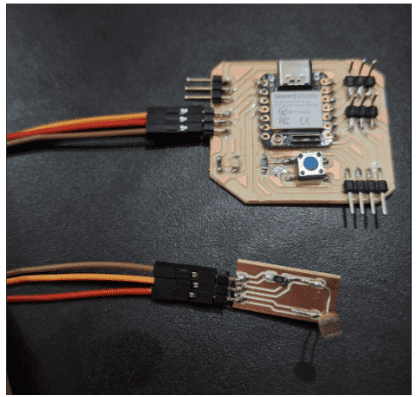
- I got together with two of my friends as we noticed the module was pretty simple, so we made our own boards for this photoresistor. I worked with Gaby specifically on this board, so you can see her documentation here
- To do this, I made my board in KiCad, starting by adding the
photoresistor
itself, 3 horizontal pins: One gor Ground , other for Power
and
another as the Signal Pin. Also there I added the 10K resistor.
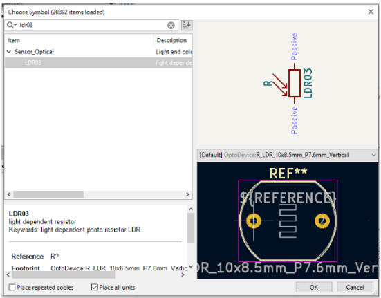
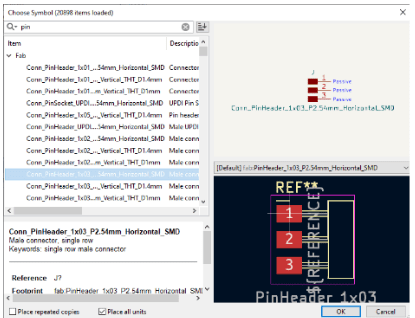
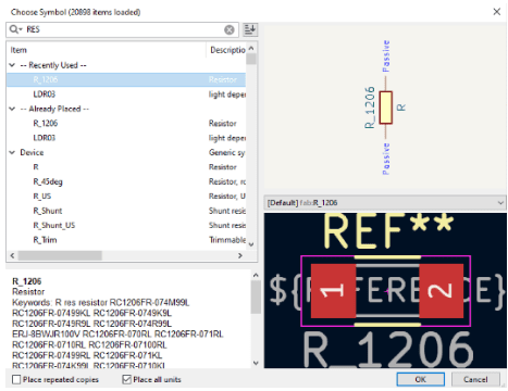
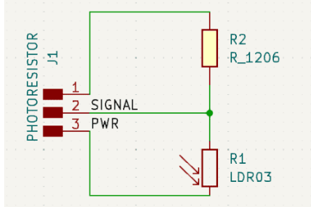
- Then I made my schematic design, connecting the Ground do the resistor and
the signal pin on the left and the power pin on my right.
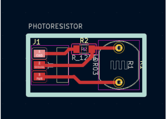
- Then I exported it and processed it using MODS
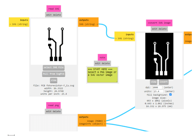
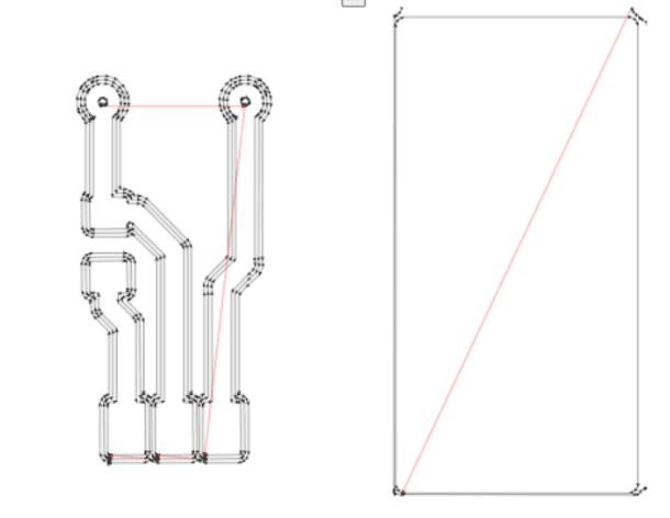
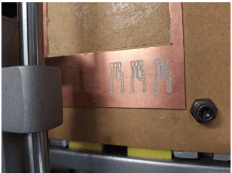
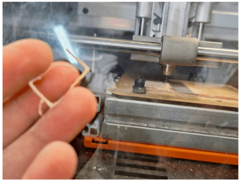
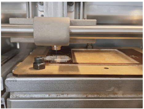
- Having this it was time to cut! It took me some attempts, since the cut
did't go so smoothly at first and I tried to make the photoresistor Through All
but I had never done that, so In the end I kept the traces over the surface.
-
Finally, that was time to solder it! It wasnt as easy as it seemed, so I
got some
help to learn how to solder it smoothly by bending the legs of the
photoresistor.
- Once It was ready, I connected it to my board, which had a red LED that I would make react to this new sensor. I made this board on week 8, so you can check it here
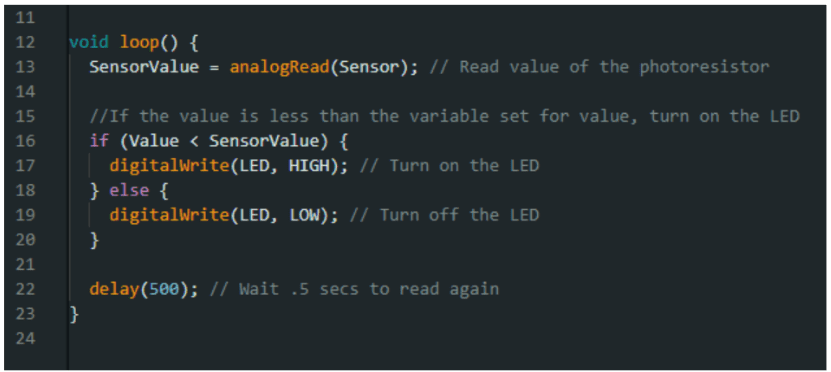
- Then I started to program the code by defining the variables I would work with. First, I indicated the position for the Sensor on the pin Analog 1 , the Led on the pin Digital 1 . There I also created a variable to save the values the sensor would perceive and another to define the sensitivity of the photoresistor.

- Next, I defined the led as an Output using setup .

- Finally, I had to create the loop with the conditional. It would read the value from the sensor and change the status of the led depending on if the sensor was covered or not: Light up the LED when the photoresistor was covered and Light off when it was normal.
- Here's the final result!!!!
---- Files ----
-
Photoresistor
-
Photoreistor + LED
- Once It was ready, I connected it to my board, which had a red LED that I would make react to this new sensor. I made this board on week 8, so you can check it here
- First I had to define what I was going to work with: I used only the movement on X as the input, so this was on pin D1. And the output was my LED, which was on D2.
