9. Output devices
First of all,to differenciate Inputs and Outputs it's pretty simple, but for practical instances: If
it can percieve information from the environment it's... an Input!, and if you use it
to provide information to the environment it's... an Output!.
Outputs can control various components like lights, motors, or displays. Understanding outputs is
essential for designing and troubleshooting electronic circuits, since these are the destination of
the codes you program. As an example, I always use a LED to verify the status of the boards I
create, so this is one of the most basic outputs. Also, you can have them soldered or use them as
modules that you can connect using jumpers.
In our group assignment we understood some concepts that are useful to understand outputs and
connect them better. Some important information related to power consumption could be:
- Component Stress: High power consumption can put extra stress on PCB components, which may lead to failures and a shorter lifespan of the board.
- Efficiency: High power consumption on a PCB can reduce the overall efficiency of the circuit.
- Heat Dissipation:Excessive power consumption on a PCB generates more heat, requiring better heat dissipation methods to prevent damage to components.
- Power Supply Requirements: High power consumption demands a more robust power supply design, including the need for voltage converters if an output requires different voltage levels. This can complicate the PCB layout and increase the size of the board..
If you wish to check what we made related to this topic, you may check our group assignment Here .
Which Outputs did I use?
For this assignment I chose to test three different outputs: A buzzer, a servomotor and Neopixels.
| Output | Description | Picture |
|---|---|---|
| Buzzer | A buzzer operates by causing a membrane or piezoelectric crystal to vibrate when an electric current is applied. This vibration generates audible sound waves, creating the characteristic tone it emits. It is controlled by electronic circuits that switch the electric current on and off as needed to produce the desired sound. Frequency determines the pitch of the sound produced by the buzzer: higher frequencies create higher-pitched tones, and vice versa. (Picture from Steren) |  |
| Servomotor | A servomotor is a device that uses feedback to control its precise position, speed, and torque. It operates by receiving signals from a controller, which adjusts its operation based on the desired position or movement. Some some have limited angles (180 degrees), while others can spin continuously in both directions. (Picture from Steren) |  |
| Neopixel | Neopixels are RGB LEDs that can be programmed to display different colors by sending specific commands through a microcontroller. Each one can be set to a desired color by specifying the intensity of red, green, and blue light components. Neopixels are popular because these can be controlled by a single data pin for many of them and already contain a resistor. (Picture from arduiner) | 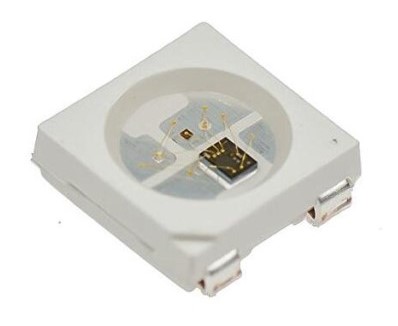 |
a) The Buzzer
-
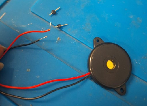
First I noticed the Buzzer has only two wires: One that's the negative (GND) and another
that is the positive (PWR or Pin). I didn't expect it, but the second one, the Red
one
works for both purposes. If you connect it directly to Power it will make sound, but if you
connect it to a pin it is programmable.
Note: The buzzer doesn't have pins, so the very first step was to solder one to each
wire.
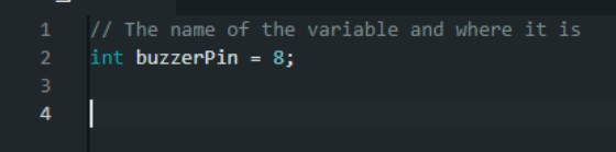
- Then I could prepare to code. As I was a little afraid to program directly from my new board
from week 8, I started using an Arduino Uno , but in the end, I migrated everything
to my board. Knowing this, the first step on the code was to tell where I had the signal
pin, in this case this was #9 and make it a variable.
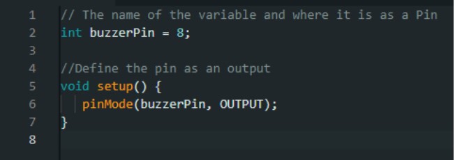
-
Then, I defined that object as an Output .
-
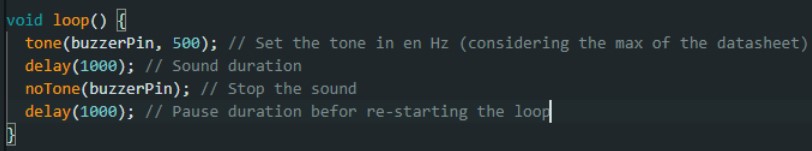
Now, It was time to make the main loop of action. Using the function Tone I could set
the pin to send the signal to, followed by a comma and the frequency of sound it should
emit. I used a starting with a value of 1000 Hx, considering the max of my buzzer's
oscilations was
3800 Hz, always check the datasheet.
Also, I used the function noTone to make silence and the function delay to
determine the lenght of each, the tone and the silence.

-
Now this was time to test the tone of the pitch. I started with 1000, but modified it to
understand which were the highs and lows. From left to right these are 1000 Hz,2500hz.
-
After that, I modified the code to make the frequencies to interact. There I realized I
could play with them and make some song later. This may sound like an ambulance or alarm,
but was my first approach, just cloning the last four lines of the code and changing the
pitch.
-
There I decided to start using ChatGPT to understand better how frequencies work.
That's how I got that the musical notes also work based on this. That way I could try some
notes. First, I googled notes and their frequencies, so I found this super useful site that
you may check Here .
That's on a piano basis, but I also got the next chart for reference on that site. There I learnt that there are different octaves to play the notes at and these come with letter C + a number to identify. I Took C3 and C4 as my first references.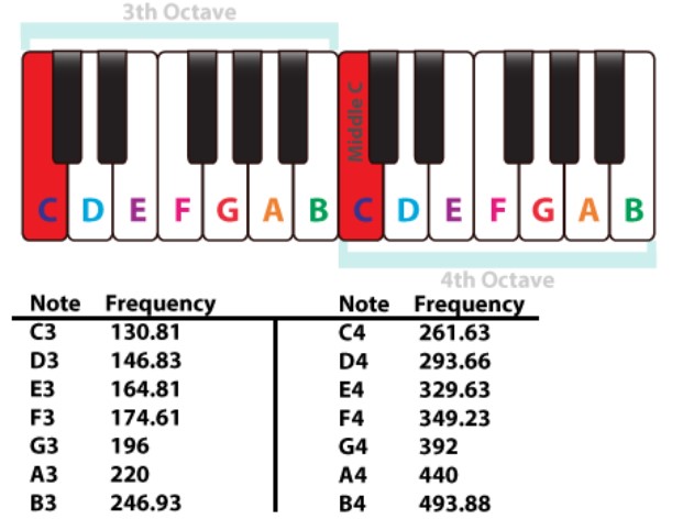
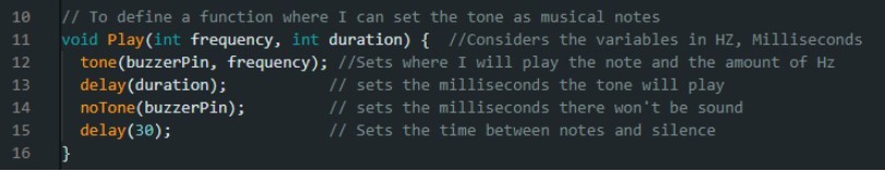
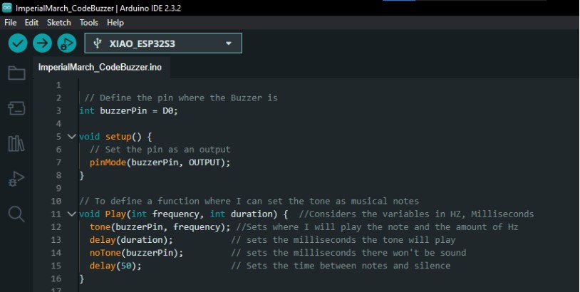
- Having this, I made a function to use on my code that would turn the singular beeps into more controlled sounds that could become notes.As you can see, The function I set on the void called Play considers two variables: The frequency in Hz for the note and the duration of it playing. I kept the Delay to separate one note from another wit a brief silence that could allow me to distinguish the notes.
- Next I Looked for an arcade type song, its notes and started writing the values in my code. I realized probably something fun could do, so I chose a fragment of "The Moon Theme" from the game Ducktales on the NES. I got the notes from Here .
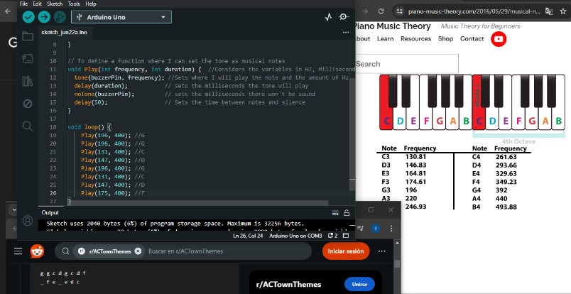
- This is how the intro sounded like. It was really fun to understand the technique, this was just like christmas lights play music!
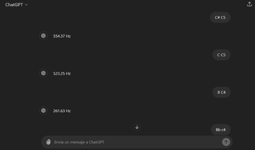
- After getting the code and the tone control, I thought of an iconic song I could play with just a few notes. I chose: The Imperial March from Star Wars. It's important to say that I tried asking ChatGPT to give me the notes for the literal song, but once I played it it sounded awful, so I had to do more research. In the end I followed this . piano tutorial in C4 and C5, following the tones from the previous site and asking Chat GPT only about the equivalences for C5 and some flat tunes
- Next, I started to transcribe the HZ and copy the lines of code. This one worked pretty decent, so I kept going. The only thing I changed was the delay between tones, some has to be longer than others. I made this based on the lenght of the visual representations of the key of the video.
- Here I decided the code was ready, and so I was to connect my own PCB. This is the final one I made last week, so you can find it If you wish to know in which Weeks I used this board, here you may find them here: at Week 8 .
Programming my board
I used the same process from week 6, you can check it out with more detail Here . But for practical purposes here are the steps:
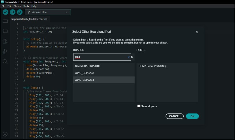
- I connected my board to the computer and made Arduino recognize my microcontroller
as a
new board. As mine is the ESP32 S3 I looked for it in the boards menu.
- Once It was ready, I only changed the name of the pins in the original code, since
the
buzzer was no longer pin 8 for
ArduinoUno, on my Xiao, This was on the pin D0.
-
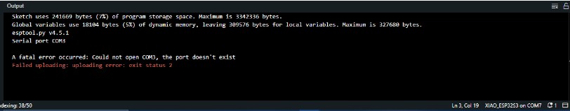
Then I just verified the code and uploaded it. Note:Make sure you change the
port too, because I forgot and it didn't appear as an error
during the verification, so until I charged my code it said it failed because the
microcontroller and port were not matching.
- This is my Final result!
b) The Servo
As I knew I could get to use a servomotor for my final project, I decided to test one and understand it better. For this week I used the one in the picture, but there are different types and sizes, this particular model is not designed to rotate 360°, so keep that in mind if you wish to use one.
-
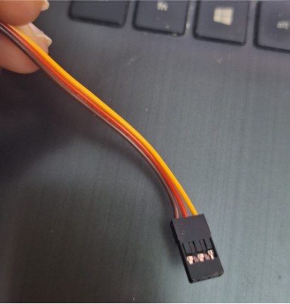
The servo has 3 pins attached already, which are the Power on the red wire,
Ground on the brown wire and the orange that is the PWM and allows you to
send signal to the output.
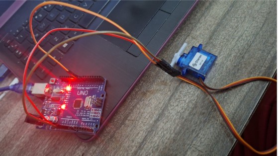
- The first I did was to keep the idea testing the code on the Arduino Uno before sending it
to my PCB. I chose the pin 9.
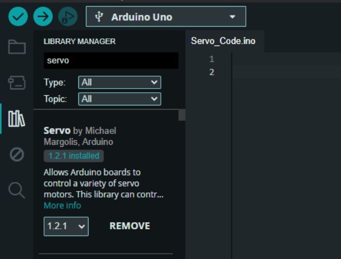
-
Then I opened Arduino IDE to add the library called Servo . I already had it, but if
you don't you can download it directly from there.
-
Once I had the library, I could search for examples to test. I chose the Knob
example to see how would it work. That opened a new file, so I just copied the code to my
current file.

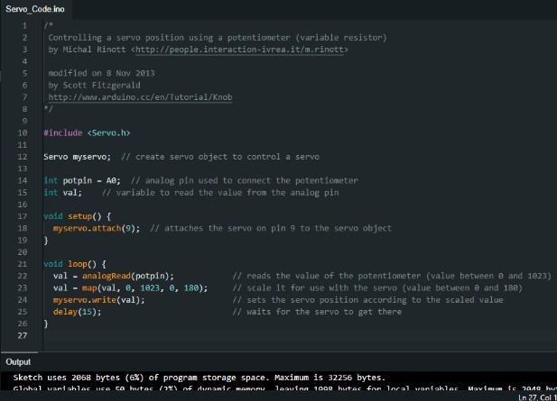
-
This is how the example looked like once uploaded.
- Then I read what the code said about the meaning of the values, and played with them a little to make a simple code. Also, I watched this youtube video to understand better. After making some questions to ChatGPT too, I felt ready to migrate from programming on the Arduino to my own board.
When I connected my board, everything was similar to the previous try with the Buzzer, but when I verified, it said that the current library for my Servo could not support my new microcontroller, so I downloaded another just in case.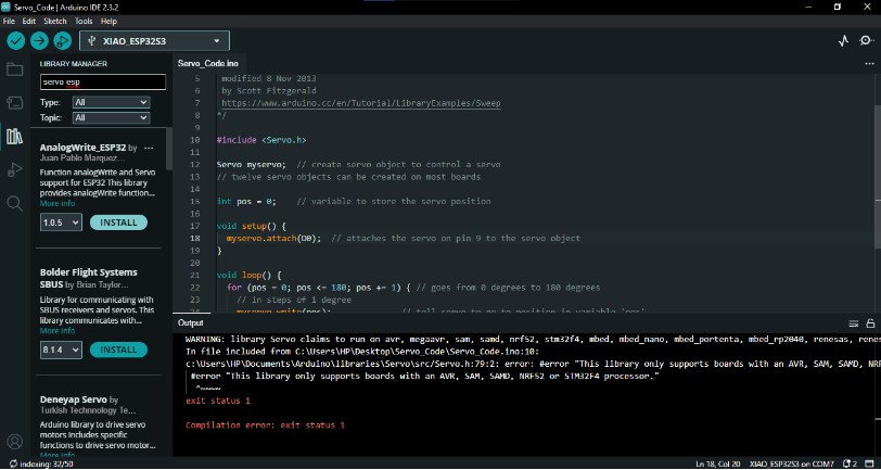
- The one I installed was the one by Keving Harrington, but It seems any other works just fine.

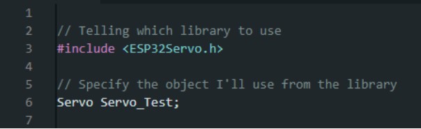
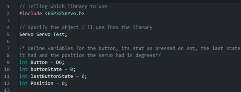
- Now, to make my own code I started by telling which library I wanted to use, mine was ESP32Servo . Also, I wrote the name of the object I would use from that specific library and named it. In this case the name is Servo_Test .
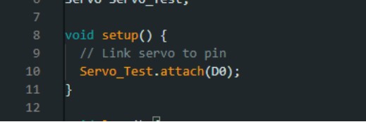
- Then, I attached the Servo to the pin on my ESP32S3. As the pin was in D0, that's the data I wrote for it to identify.
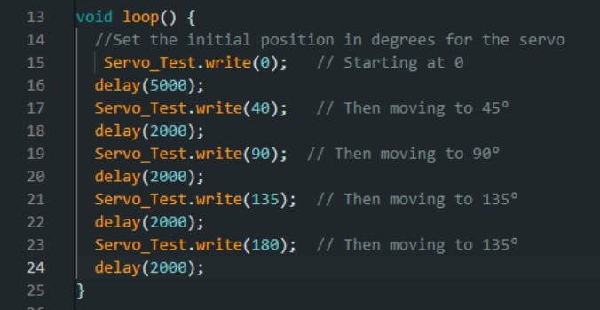
- Next I added the loop for the code, where my values for the servo would write on degrees, starting with an initial position of 0 where it would stay 5 seconds. Then rotating 45° each 2 seconds.
- This is how it looks like!
- Now, I just wanted to add another option to my code and link it's movement to a button, so I made a different code starting from the original one. The first step here was to add the button as a Variable and define it's pin, then I had to add other variables to state the changes the button would make: the state, the position for the servo and a variable to keep track on the state of the button (pressed or not).
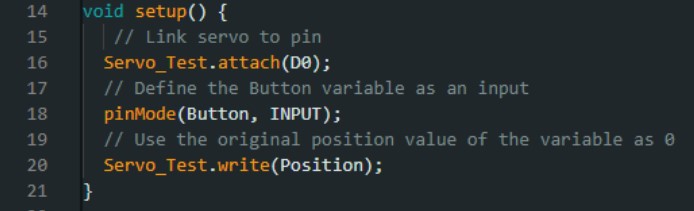
- Then, I defined this new button variable as an input , attached again the servo to it's pin and defined a write function that would take the value from the variable position
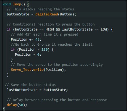
- Then, I created the loop for the action, where the data from the variable buttonState would read the signal from the button itself. Then, with the conditional if , it would read change the position 45° each time the button got pressed, resetting to the position 0 each time the servo reached the limit of the 180° and allowing me to press the button once again. Here, I also added a small delay of reaction, to control the sensitivity of the button and servo interaction.
- This is the final result of this code!
c) Neopixels: Making a new board
In week 8 I made a board to control everything, but as I pictured my final project, I wanted to take advantage of another board that would imitate a light Bulb. To make it possible, I decided to use Neopixels, so that I could change their color and intensity as a smart bulb.
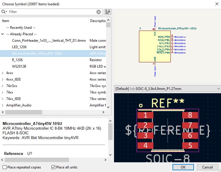
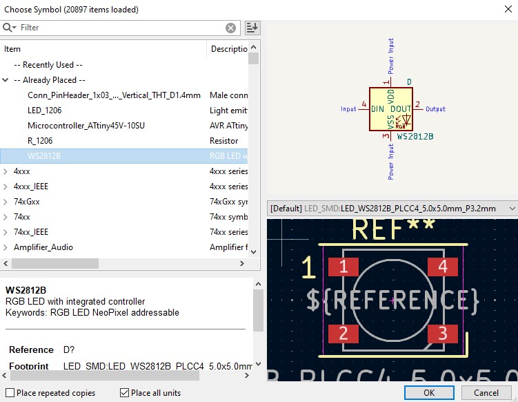
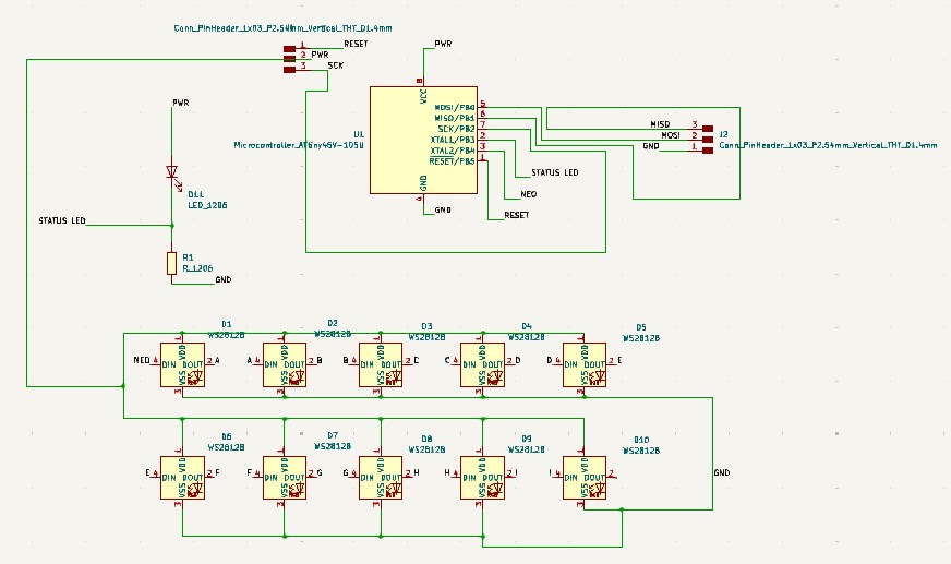
As I wasn't sure If I could wire it separately in the final version, I included a microcontroller to program the Neopixels as well. Here you will see how I Made this board:- First, I started my schematic adding the microcontroller, that was an Attiny45, 10
Neopixels and 3 row Pins. I also had included a Status Led with its
resistor.
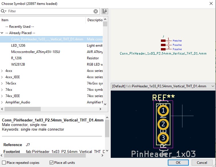
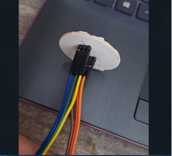
- I wired the 3 row pins to use them as the 6 required to program a board, and also because the Attiny45 doesn't have many. These would be: MISO,MOSI,SCK,RESET,GND,PWR. I chose them to be through all so that these wouldn't interfere on the view, so I could hide them later with the structure of my final project.
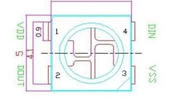
- Then, I started to connect the Neopixels. These are Outputs that transfer data from a single pin, so each of them sends information to the next one. That's why, the neopixel has 4 different touchpoints: VSS (The negative or GND equivalent), VDD (The positive or PWR equivalent), DIN (The input of data), DOUT (The output of data).
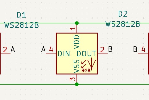
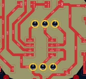
- After connecting everything, I defined the pin to link the "master Neopixel" and added 9 more, to get 10 in total. This is how my final version of the schematic looks like.
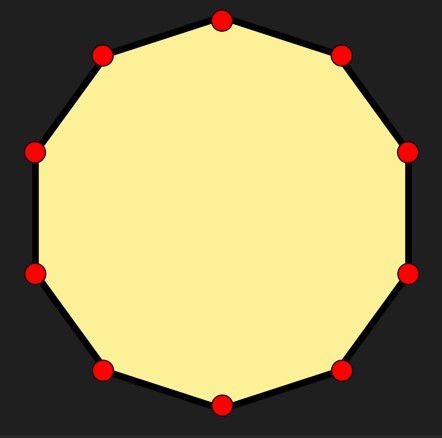
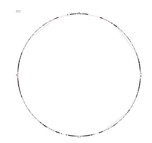
- Now, it was time to add everything to the PCB Editor and wire everything. The design rules I followed were based on the maximum diameter I needed to make this aestethic enough. That's why I added a picture of a decagon as my template.
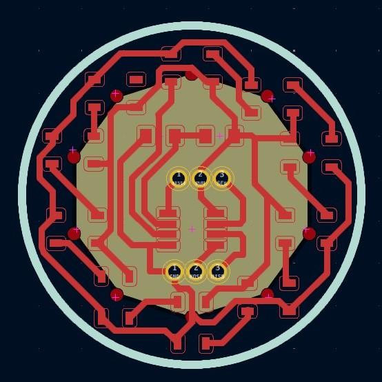
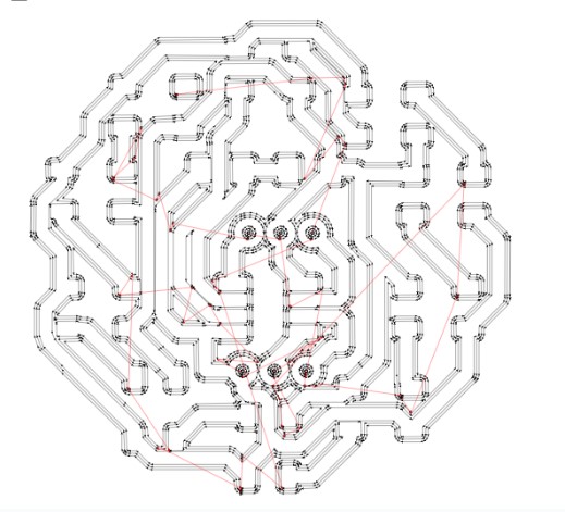
- Then it was time to export and prepare the files in MODS. The rules were the same as in previous boards: selected 1/64 for traces and 1/32 for the outline. Also, only 3 offsets for the engraving.
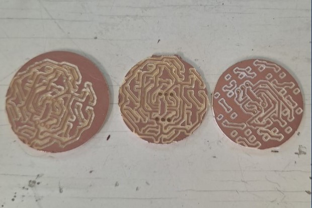
- As I cut, The first time I decided to change the outline diameter last minute, once the traces were cut already. I do not recommend this because it ruined my first board. Always export the traces and outline by pairs, If not, you may lose the real dimenssion or origin of the whole thing. Even so, In the end I just managed to cut the second one perfectly, here's a comparission, that includes also a first attempt where I forgot to wire the neopixel inputs and outputs for data (Now it's funny, then I felt really dumb).

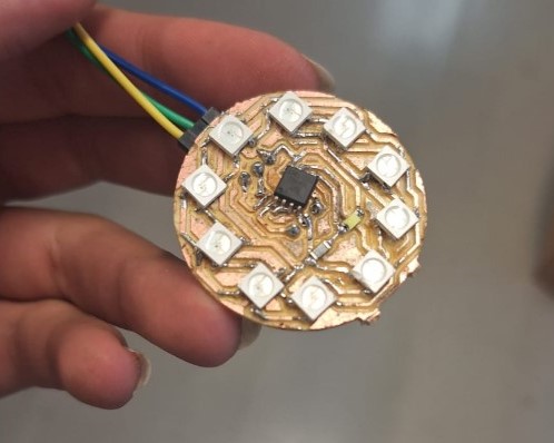
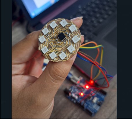
- Then I had to solder everything. Starting from the middle with the microcontroller and finally with the Neopixels.
- This is how It looked lik once ready. Keep in mind that I removed the LED and resistor for aesthetic reasons later, since I didn't find it very functional either.
c) Neopixels: Programming a board with another
Now that this new board was ready, I needed to program it directly to light up the neopixels. It's important to say that for this week's practice I programmed my board using an ArduinoUno, because unlike my ESP32s3, the microcontroller I used with my neopixel board is an Attiny45, so doesn't have a built-in direct programming interface like usb. Then, it was easier to use an Arduino Board first.
-
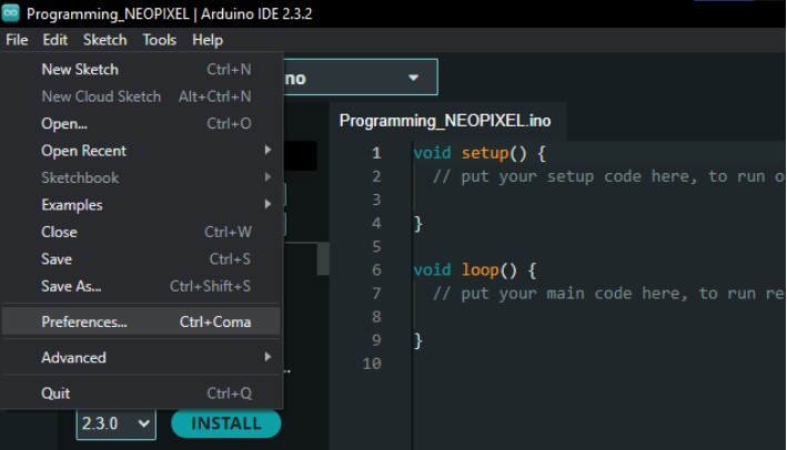
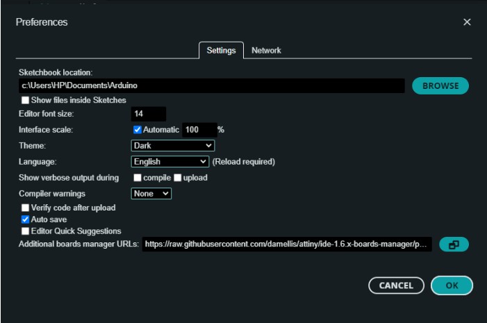
The first step was to look for the microcontroller library in Arduino IDE and install it.
This worked by opening the preferences menu and pasting the following
URL . Then it installed, and I restarted the program to get the changes
ready.
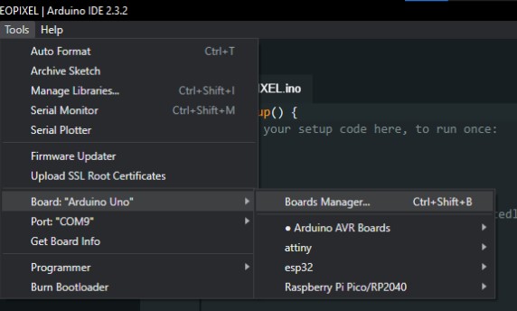
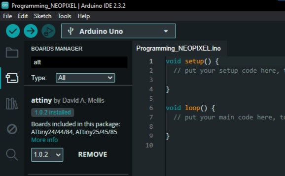
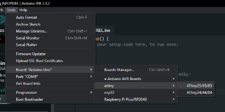
- There, I used the tools menu and looked for the option of boards manager .
There it popped up another menu where I looked for the library “attiny” and installed it.
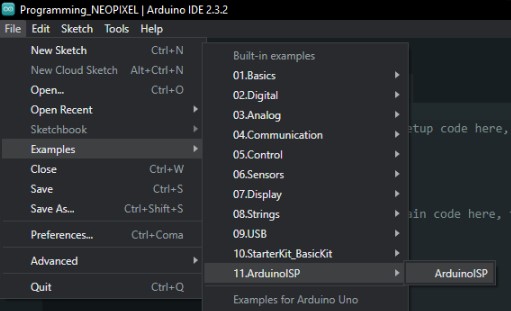
- Once installed, I opened a file called ArduinoISP from the examples in the folder
with the same name, at the files menu.
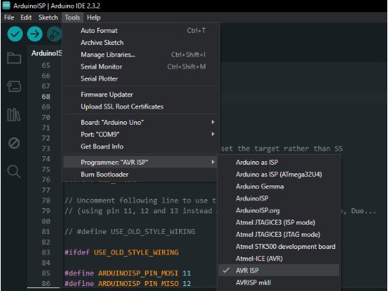
- It opened a new file where I went on tools , then programmer and selected
the option that said Arduino as ISP. Then I uploaded that code to the Arduino Uno.
- Once that was ready, I opened the option board
in the main page for the code. There I looked for the one inside the Attiny
folder and selected the one that said Attiny 25/45/85 .
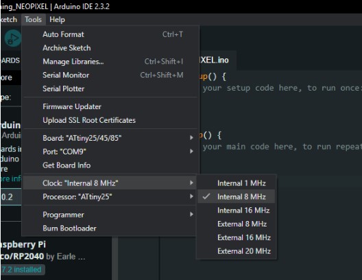
- Now, selecting the clock in that same menu was next. As I would be working with Neopixels I had to choose the internal 8MHz.
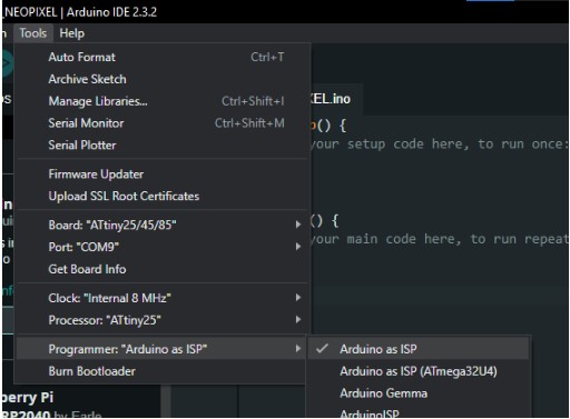
- Next I had to select the programmer. Here I chose the Arduino as ISP option to keep the changes from that other file. Also, I had to select the processor, that for me would be an attiny 45.
- Now, this is the board I made for my final project, its designed to mimic a light bulb once everything is assembled. The first thing I did was to check the pins, assign a color to each type and verify with my design.
- This colors matched the ones used by the example to program the Attiny45 using an ArduinoUno. This comes from a PDF an assessor from our Fab sent and you can find it attached with the files if you want to use it, it's in spanish but the graphics are understandable enough. The picture comes from there, I only added the names to each wire.
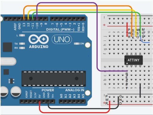
- Then, following the wiring on the previous diagram, I connected my own board to the Arduino.
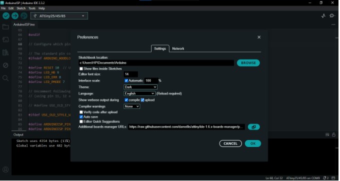
- Once everything was connected, I opened the preferences menu once again and set it to the option show verbose .
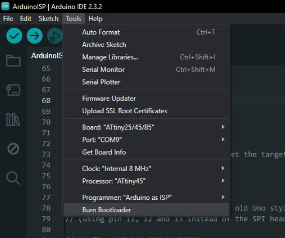
- Then, I verified that everything were right. As it was, then I clicked on the option Burn Bootloader. Note: You only have to this once, after that, the microcontroller will only need you to use the programmer to uploade the code from it.
c) Neopixels: The actual program
-
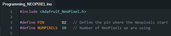
Now, there was time to start checking the code itself, where wanted to create a color fade
from blue to pink. The first step here was to define the variables and include the library.
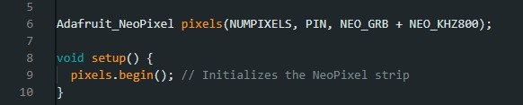
- The first line sets up the NeoPixel strip, making it ready to use.The second initializes an
object named pixels to control a strip of NeoPixels.
NUMPIXELS specifies the number of LEDs.
PIN is the microcontroller pin connected to the NeoPixel strip.
NEO_GRB indicates the color order (Green, Red, Blue) and NEO_KHZ800 the
communication speed (800 kHz) for the NeoPixels.
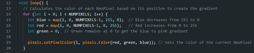
- In the void loop() section, the code runs continuously after setup. It calculates the
color of each NeoPixel based on its position to create a gradient effect. The
for loop goes through each LED, calculating the blue color value to decrease from 255
to 0 and the red color value to increase from 0 to 255, while the green color remains at 0.
It then sets the color of each LED with pixels.setPixelColor(i, pixels.Color(red, green,
blue)).
- In the pixels.show() section, the code sends the updated color information to the
NeoPixel strip, making the colors visible. The delay(50) function pauses the code for
50 milliseconds, controlling the speed of the gradient effect. Adjusting this value changes
how quickly the colors transition.

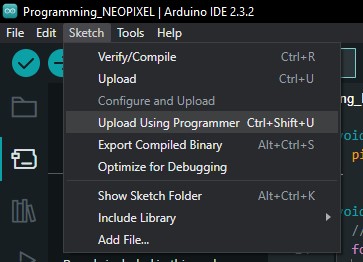
- Once that the code was ready, to upload it, I simply clicked on Sketch , and then
"Upload using programmer".
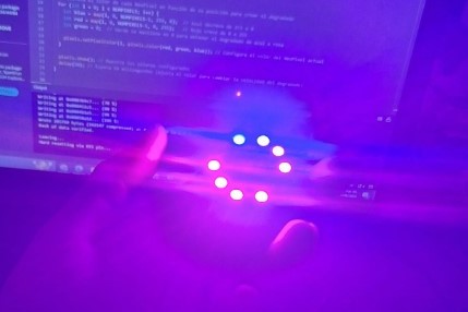
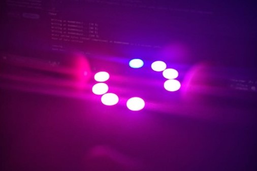
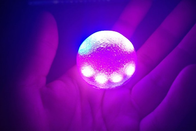
- This is how it looked like as the Final result! (In one of the pictures I put the resin cap on top to see how it would look later in the final project).
---- Files ----
-
Buzzer
-
Imperial March code
-
Servo
-
Servo Code
-
Servo Button Code
-
Neopixel
-
Board design Files + SVG
-
Neopixels Code
- This is how it looked like as the Final result! (In one of the pictures I put the resin cap on top to see how it would look later in the final project).
- Now, selecting the clock in that same menu was next. As I would be working with Neopixels I had to choose the internal 8MHz.
- I wired the 3 row pins to use them as the 6 required to program a board, and also because the Attiny45 doesn't have many. These would be: MISO,MOSI,SCK,RESET,GND,PWR. I chose them to be through all so that these wouldn't interfere on the view, so I could hide them later with the structure of my final project.
-
The servo has 3 pins attached already, which are the Power on the red wire,
Ground on the brown wire and the orange that is the PWM and allows you to
send signal to the output.
- Having this, I made a function to use on my code that would turn the singular beeps into more controlled sounds that could become notes.As you can see, The function I set on the void called Play considers two variables: The frequency in Hz for the note and the duration of it playing. I kept the Delay to separate one note from another wit a brief silence that could allow me to distinguish the notes.