6. Embedded Programming
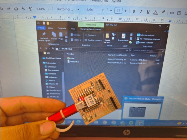
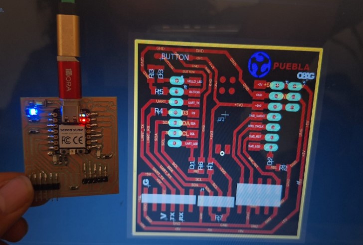
This week's practice included using the PCB I made during Week 4 . My advice I to take good care of everything you create, because I had to solder some pins again. Also, during this week, I had to watch some youtube tutorials, dust some old learnings I had and understand better the components and why I was using them.
- The group assignment: The basics of coding in c++ and python -
This week my FAB site was incredibly helpful, because It was my first time using Arduino and Python, which were the coding programs I used. The group assignment and lecture included a lot of tips and definitions for some elements around coding. Also, the page has some source code I took as my base, from the downloads section, if you want to see more you may click here .
Some basic concepts
| Concept | Description |
|---|---|
| Variable | The option that allows you to save data and assign it a value. |
| Control structures: If- Else | Are conditionals that state what will happen under specific contexts or situations. |
| Loop: For-While | These state the times a cycle will repeat and under which conditions. The loop “For” states what will happen from the beginning to a specific variable. The loop “While” will occur every time the conditions are met. |
| Function | It packs code in a simple task to complete, that can repeat many times and make the code a reusable component instead of having many lines of it. |
| Input | State of a pin that allows it to recieve a signal from another source. |
| Output | State of a pin that allows it to send a signal to another source. |
| Libraries | These are available in Arduino, by adding a library you can add the details of your component and make it possible to include it in your code . |
| Comments | Allow you to document and add notes on different sections of the code. I used them to remember the purpose of different parts of the code. |
| Comments in C++ (Arduino) | To write single line comments you use // before the note, to write comments that go beyond a line you use /* to open and */ to close the comment section. |
| Comments in Python | To write single line comments you use # before the note, to write comments that go beyond a line you use … to open and … to close the comment section. |
---- Programming my board----
- The first step to program it, was to reset the Xiao and connect it to the
computer. To do so I pressed the b button from it's lower right and it
should open as an USB.
- Once i confirmed that it was connected, I opened Arduino. There I thought
something wasn't right, because there it didn't read the Xiao as a board. The problem
was that it wasn't recognizing the port, so I reset it once again, but this time
pressing the R on the left corner.
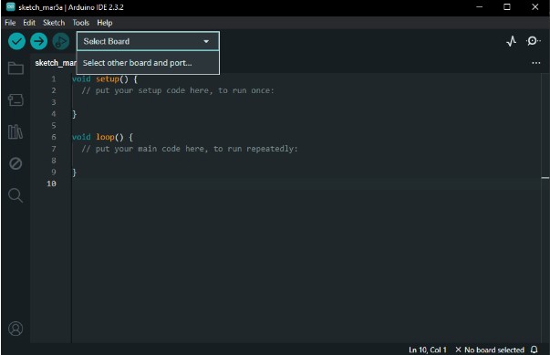
- If you don't see the Xiao still, it's because you're using a charging cable, not one
that allows you to send data. It must show the name of a board like in this picture.
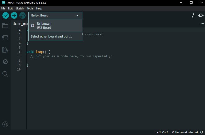
- Once I had the port, I had to open the /“Select board” option and look
for the one that said Seeed XIAO RP2040 .

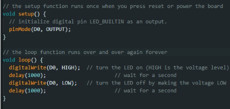
- Now, I was ready to start programming, so I followed a blink tutorial from the
Arduino official site. This was used by my local instructor as well and I
copied it to the Arduino app. It's important to say that I started from the base code,
but made some adjustments.

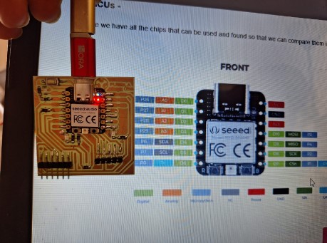
- The next step was checking the Xiao's pins and comparing them to a picture available on
the group assignment from my fab to know their names for coding. I had to replace the
name of the pin where I had a LED to make it blink. In this case I used the one called
D0 everywhere that previously had the LED_BUILTIN legend on the code.
- Then I checked the interval between blinks. It goes where it says delay and
each 1000 equals a second, if I wanted it to change the time I could play with this
setting. It's important to say that this can't be 0, because that works so fast, it
isn't possible to know whether it changed or stayed lit.
- Once that was ready, I clicked on the upload button. It made the code to start
compiling on the PCB.
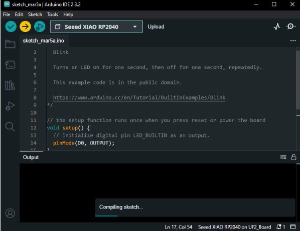
Note: I had to reset my Xiao again, because It appeared as an error, now it connected again and it kept changing from time to time to be named COM3 instead of UF2
- Here it is with the first code!
---- Modifying the code ----
- Now I tried to do the same blink with all of my leds , so I used a picture
of the rails behind the Xiao to get the names of their respective pins and replace
them.

- Here it is, this one looks like christmas lights, but slower, for this video I
decreased the time in the delay to 500.
- Having this, I reset the board again and decided to play with the button. I started to code it, so I added a variable for the state of when it's pressed that would change between HIGH while pressed and LOW when it wasn't.
- Be careful to check that your tags are well written, here Capital letters count for
the program to read the code properly.

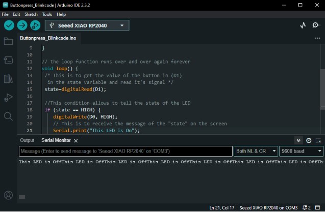
- This is how it looks with the button pressed!
- I also wanted to have feedback on the device telling me that this was on, so I
showed the Serial Monitor .
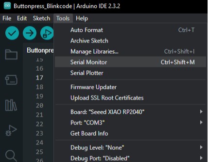
- And then added the function Serial.println + the message I wanted between
braces. In this case it was to tell the LED's status as I pressed the button.
- Important: It's also possible to use the function “Serial.print” alone, but
it won't look good, because it writes the legend in the same line and also almost
crashes my Arduino.

---- Programming a Neopixel Adafruit ----
- Then I made a new document and installed a library for the other component my
board
has: Adafruit Neopixel LED.
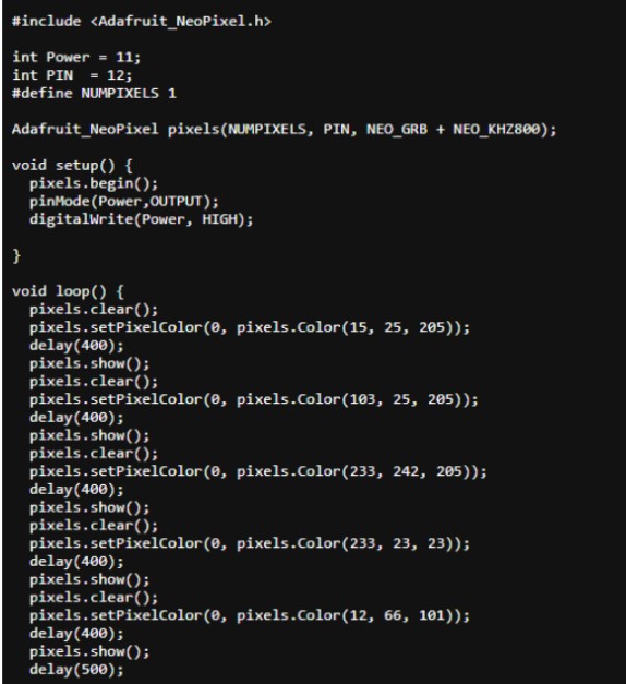
- After that, I opened a code available on my Fab,this works for Arduino itself,
but
it is also possible to adapt it.
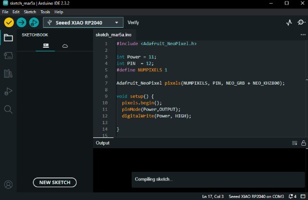
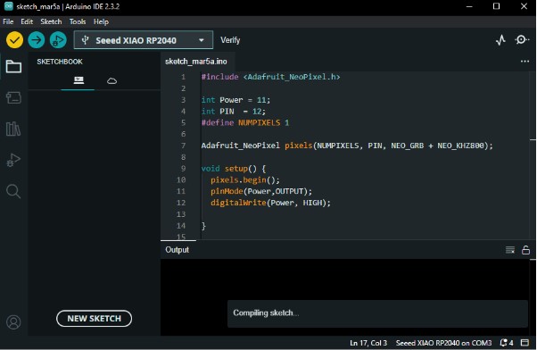
- I copied and pasted it on Arduino and verified it with the verify
tool.
Just to check how it looked on the Xiao and understand better which variables
did
what.
- This is a video of how bright it was when I saved it to the board. It was too
intense, so I looked for a function that would allow me to lower the intensity
of it. (I asked chatGPT lol)
- So, to change it, I added the function “setBrightness() and when I
asked ChatGPT it also suggested that you can change the intensity between a 0 to
255 spectrum.

- Here is the difference after lowering the intensity and playing with the
variable values.
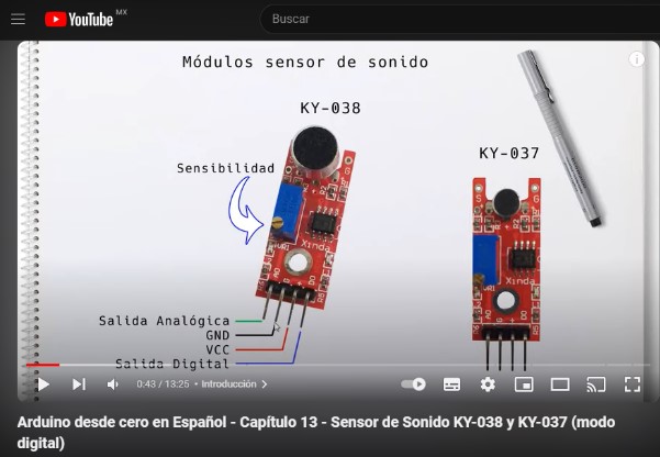
---- Programming a sound sensor ----
- I used an sound sensor model KY-037, that comes with an arduino Kit. As it is
something very new to me, I followed a tutorial from Youtube to start coding. It
has subtitles and was very useful, you may find it
here if youre interested.
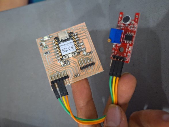
- The first step was to connect the sensor to my board. To do so, I connected the
pins using female-female jumpers.
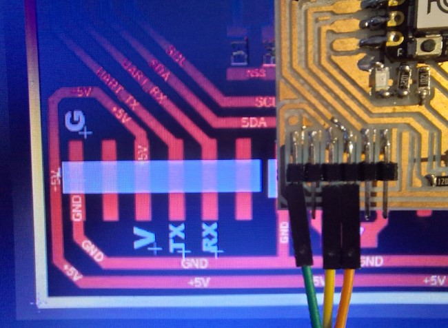
- To do so, I had to check what I was connecting to and where. During week 4, we
received an image for reference to solder, this had names for the pieces that
would go above, so I used it to check the traces of my board. The elements I
connected first were from the side of my board: ground (G), voltage
(V) and a pin from the Xiao to Transmit (Tx) the information it
received.
- Next, I connected the pins from the sensor. The symbols were mostly the same:
Voltage (V) , Ground (G) and the Digital Output (DO) .

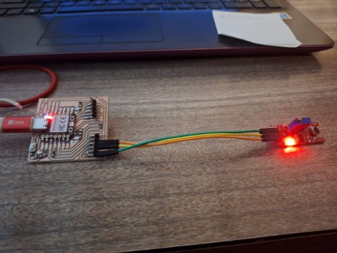
- Once everything was connected with the pins, I plugged it to the computer and
reset the previous codes.
- Then I had to identify the pins that connected directly to the sensor.
To do so, I followed the route from the reference picture of the traces and also
the name for analog pins that the group assignment offered.

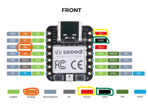
Note: Each picture has the pins and respective traces marked on the color of the cable I used.
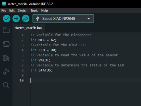
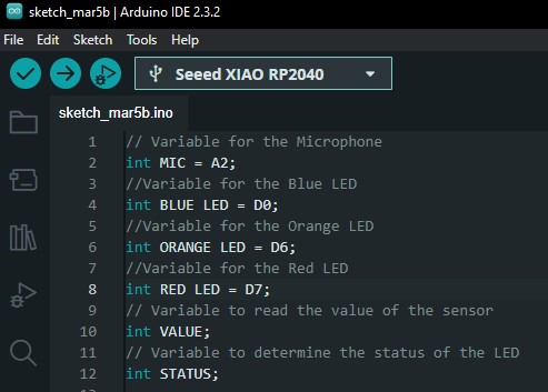
- Now it was time to start coding. The first step was to define the Variables . I used the tag Int as in the previous codes, and gave a name To the microphone and the LED. I made them equal to the names of the pins I identified on the previous step.
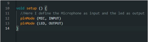
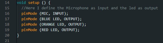
- After that, I defined the input and output ot the signal sent.
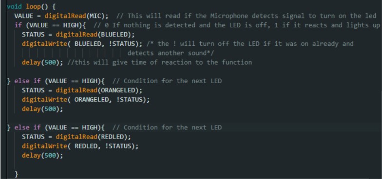
- Now, It was time to create the loop of reaction and interaction between the microphone and the LED.

- The next step was to add a delay to make it take half a second between functions.Right after I verified the code.
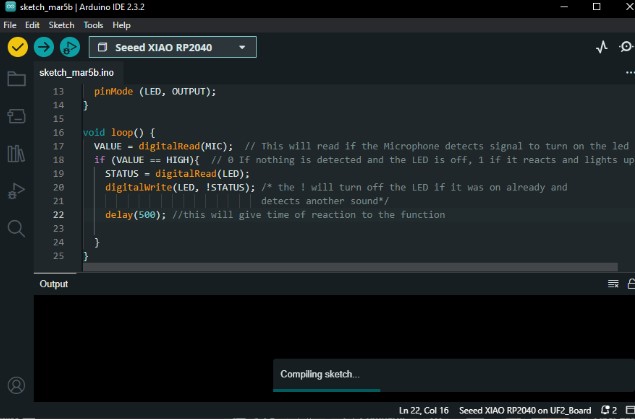
- Here it is the first result! It worked!I made a test snapping my fingers.
- Even though it worked just fine, I decided to use all of my LEDs and make it mine, so the next part comes from my interpretation of what worked. I started by adding new variables for the other two LEDS.
- Next, I added the new LEDs as outputs.
- And finally, I added more reactions under the conditional else . I had to remove the spaces between the names of the variables here.

Note: It didn't work, so I kept making some adjustments.
- Then I tried to use else if , but realized it didn't really work either, Because it only turned on the original Blue LED. Here I realized I needed something different.
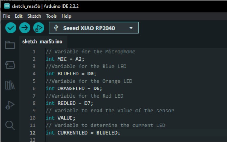
- I couldn't really get why this wasn't working, so I asked chatGPT what was the problem with what I wanted. It said that the original code had an on-off logic for the original LED, but there wasn't anything to state that the LED would change with each sound, so It advised me to have a variable to define the LED in use. I called it CURRENTLED .
- As the inputs and outputs stayed the same, I went down to interpret the next part. Here I had to change from starting with the blue LED off, to have it on, so the loop would turn off the current LED when it heard something.
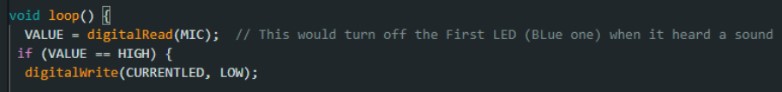
- Then I assigned another conditional If and else if to make the variable current led change between the three each time it captured a sound.
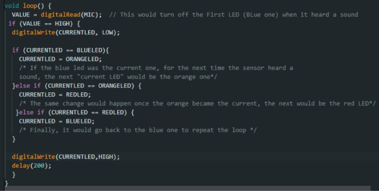
- This time It worked exactly how I wanted! So I tested it again, snapping my fingers.
- As you could see, the reaction was nice, but I wanted it to react better, because It had to be really close to the sound source to catch it. To increase the sensitivity of the sensor, there is a screw. The more you move it clockwise, the more sensitive the microphone will be.
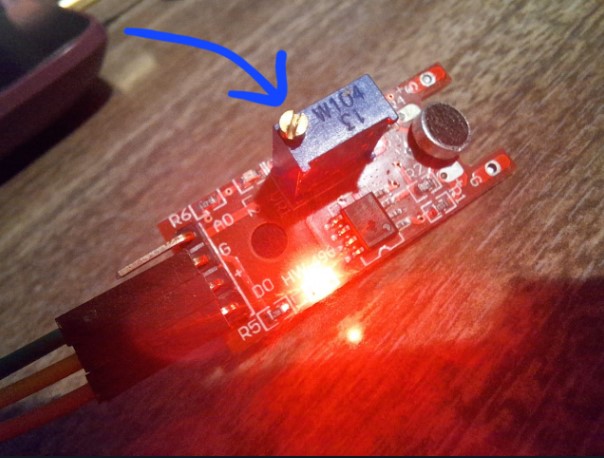
Note:After adjusting it it was ready!
Final shot!
Note: I don't own the rights of the song in the background, the source comes from here
All Rights for the song "Axel F" to Harold Faltermeyer ℗ 1984 UMG Recordings, Inc. - Now it was time to start coding. The first step was to define the Variables . I used the tag Int as in the previous codes, and gave a name To the microphone and the LED. I made them equal to the names of the pins I identified on the previous step.
- Then I made a new document and installed a library for the other component my
board
has: Adafruit Neopixel LED.
