4. Electronics production
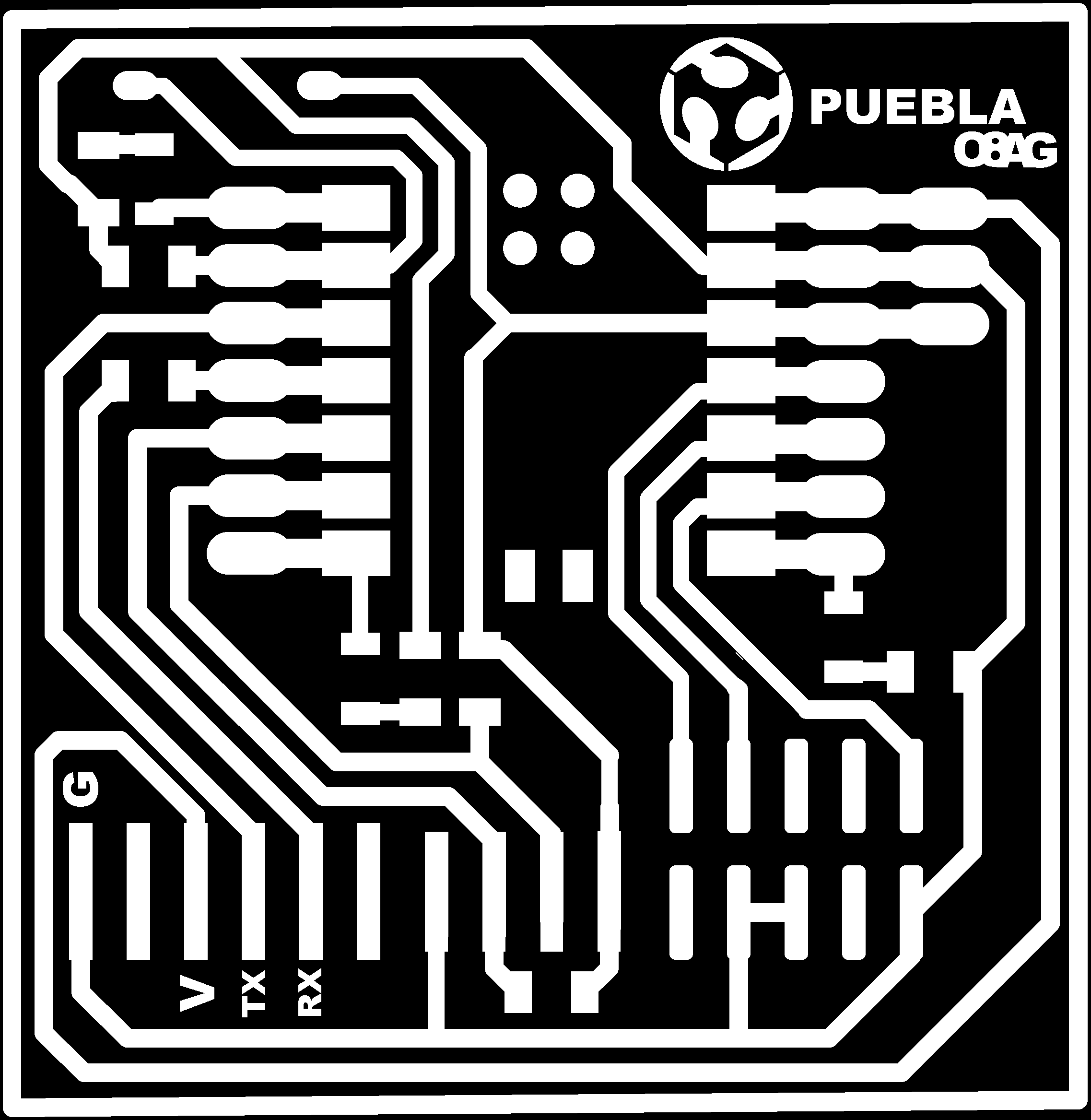
This week we worked on a PCB, which stands for "Printed Circuit Board". There are different types of them, also there are different finishes as the ones you may find inside of your electronics. Also there are different types of PCB's materials, that can resist differently any fire caused by the circuit's malfunction. During this week we worked with FR4 because it's easier to find in Mexico. There's more information available about this matter here .
Important tools
| Element | What is it? When did I use it? | Picture |
|---|---|---|
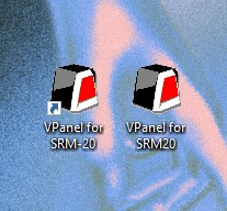
| ROLAND SRM-20 | This is the mini mill I used for cutting and engraving the PCB. To use it I had to download VPanel for SRM20 as controller + a driver. |  |
| V-bit and two flute end mill | The first one a is 15 degree V-bit for engraving and the second is a 0.8 mm diameter two flute mill for cutting. These adjust on the SRM-20 and are very delicate, so ther was a personal set for each of us. | 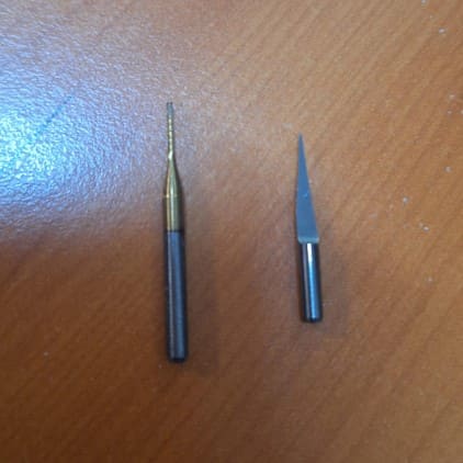 |
| Hex Keys | These had different sizes, I used the smaller ones to change the tool on the head of the SRM-20. The bigger ones were for the screws that secured the sacrificial bed to the base. |  |
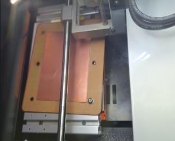
| Sacrificial Bed + Copper-Clad sheet FR4 | The first one was the base for the cut, it was made from a 2mm MDF panel and had 6 holes to secure it to the machine. I put the Copper-clad sheet over this, using double-sided tape to fix it. It is needed to use a "sacrificial bed" to prevent trespassing the copper sheet in case the machine's callibration through the cut fails and cuts too deep. This helps to protect the machine and the cutting tools. | 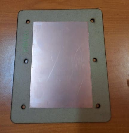 |
| Soldering Iron | This tool allows you to melt the solder and works with electrical heating, so I worked with it at 350 degrees aprox. It also Has a sponge where you can clean the tip. |  |
| Solder | This is the material that melts with the soldering iron, it links components together and hardens almost immediately when you stop heating it. It's like a fragile string and I used in a roll and tube presentation. | 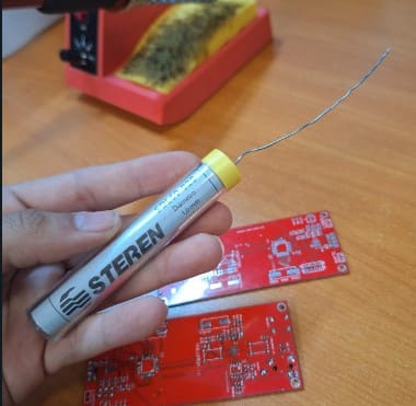 |
| Desoldering Pump | This pen-like tool can vacuum solder you may want to remove . It creates a void that is released when you press a button and sucks in the solder, but first you have to melt the solder. | 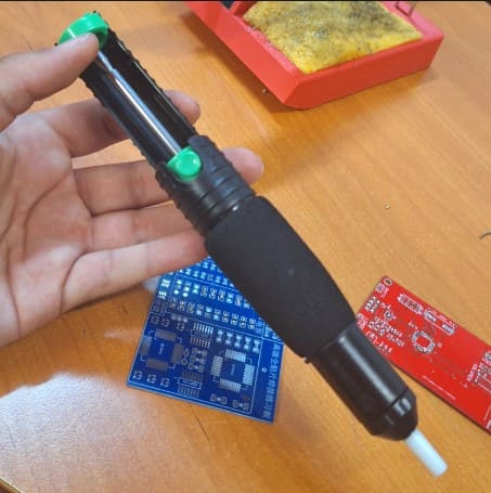 |
---- Preparing The cut ----
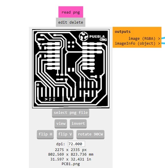
- First, my FabLab shared two PNG files, one for the engraving and one for the cutting of the PCB.
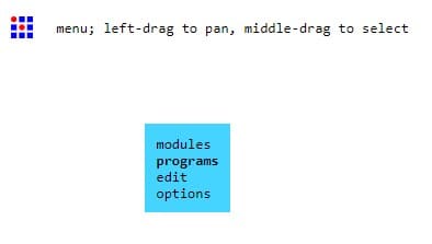
- Right click to open the menu, then on the "programs" option.
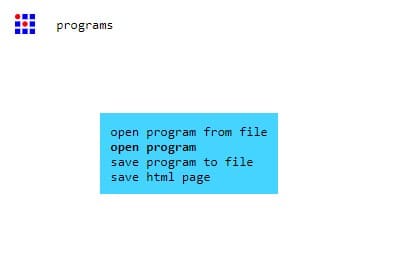
- Then click on the "open program" option.
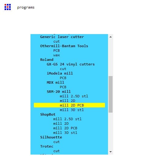
- Next, select the "mill 2D PCB" option.
- Here, a menu popped up, It is full of nodes, so it's important to find the right one.
- There I added the PNG for engraving first on the read PNG node.
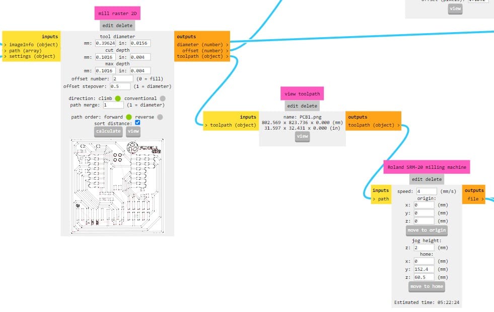
- Finally I looked for the mill raster 3D and Roland SRM-20 milling machine nodes to set the amount offsets and origin. The amount of offsets determines the amount of times the cutter will pass around an area, in this case there were only 2 needed. I also repeated the process with the PNG for the cut and downloaded the files. In case you want a preview, it is available when you click on the "calculate" button.
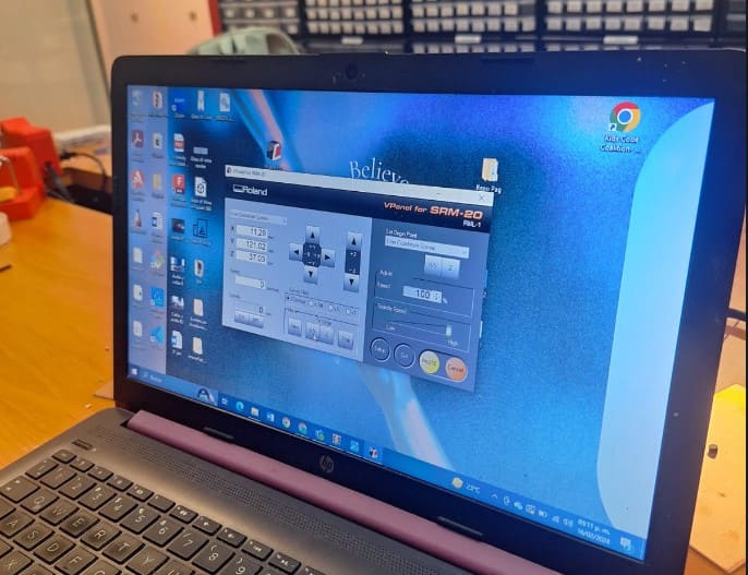
- First I downloaded the drivers and softwares to control the machine from my computer. I used "VPanel for SRM-20" It's Important to know that It won't open If the machine is not connected.
- Then I connected the machine to my computer and opened the software, It looks this way when you first open it. You have some arrows to move the head to the sides (XY Axis) and up and down (Z Axis)
- Then I used the Hex Key To set my material ready on the table and fix it with the srews.
- Then I started to move the head of the tool to match the corner of my material, I wanted it to be really close without hitting, so I used a paper sheet between the tool and my material, I lowered the Z Axis lower and checked the freedom of movement the paper had, once it couldn't really move the origin was ready to be set. It is very important to know that the tool won't move if the machine's door is open. Make sure you close it!
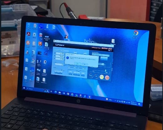
- To set the origin I was asked a confirmation by the program, but everything was set. After this the only thing I did was to check if turning on the machine there was an actual contact with the material by clicking the Spindle button
- Then I uploaded one of the files I downloaded from Mods, I clicked on Cut and browsed my file. I started with the one that would be engraved but it was very simmilar for both, cutting and engraving, the only thing I did inbetween was to change the tools of the head.
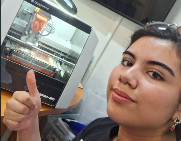
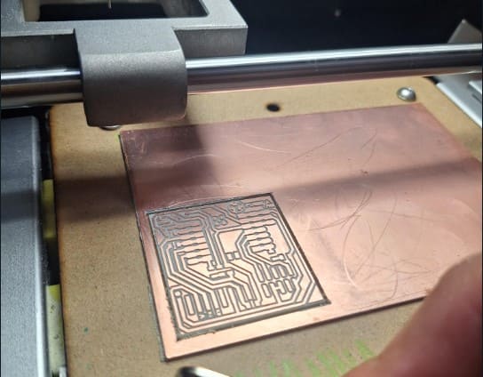
- Then I let the machine do it's work, It took about 20 minutes for the engraving and 5-6 minutes to cut.
- Here I am waiting for it and the final result, fortunately I only had to cut it once!
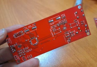
- Now that I had my own PCB, I had to solder some components to it, I had never done it before, so I really had to practice, here are some of my practice PCBs from the days before I actually decided to try in the real thing.
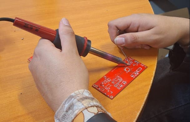
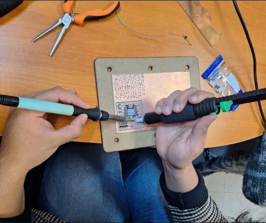
- To start soldering, I followed a professor's advise: First check that the tip of the soldering iron is clean (you clean it with the wet sponge), then you heat your working area and finally you bring the soldering tin close very quickly.
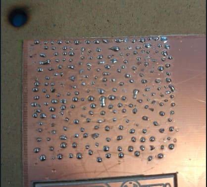
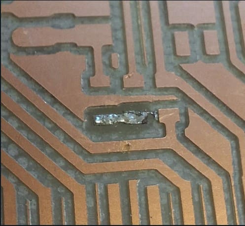
- As you can see here, my technique wasn't the best, so after my first tries I would have some tiny dots of solder (It happened many many times lol).
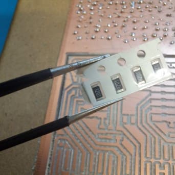
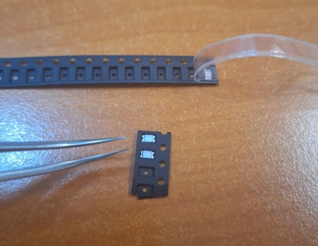
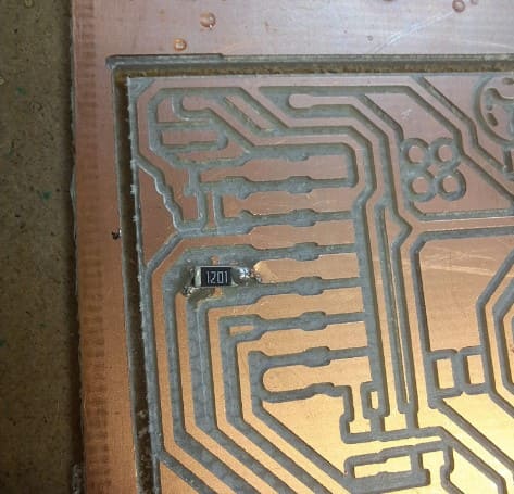
- After practicing a lot, I felt ready to try to solder some components, so I first tried with resistances. As these are very small, the process gos by: First make a dot, then grab the component and connect it with one hand using tweezers, as the other melts the first dot of solder again. Then you just need to add another dot on the other corner.
- I practiced enough to feel ready, but the material of my own PCB felt a lot different because it didn't have a finish, so I made a lot of solder dots until I felt it was safe to start with my components.
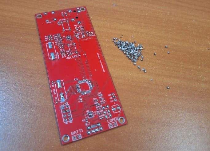
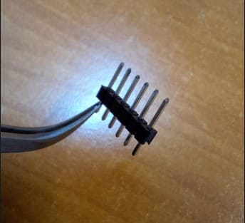
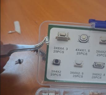
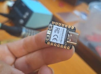
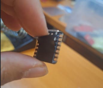
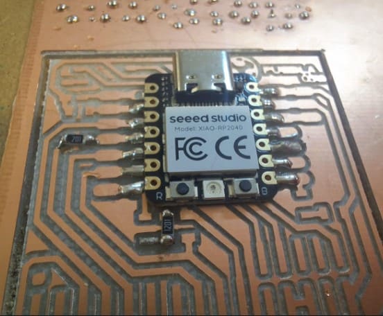
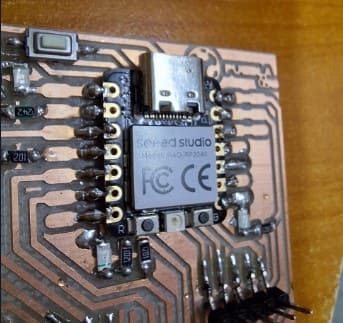
- Then I gathered all my components, I used a button, 7 resistances, 3 leds, pins and a "Xiao" that I had to cover with insulating tape to prevent any damage because it has connections under. Here are some of the pictures.
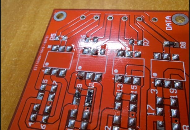
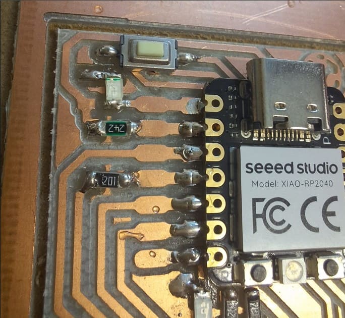
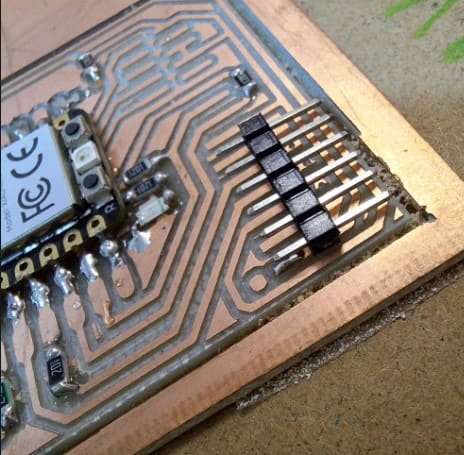
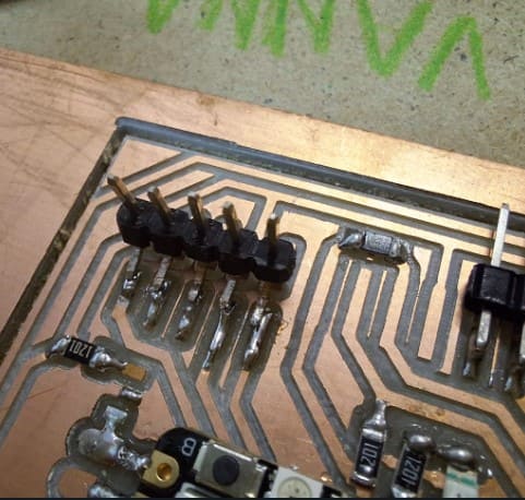
- Finaly I started to solder my components one by one. The first ones were the pieces in the middle starting from the resistances, the last and hardest were the pins because I had to bend and make a bridge of solder.
- Before testing the PCB, I checked that my pieces were not invading another line, also there was a chance that soldering could have gone to the wrong places. To verify if there was a clean line I used a Multimeter. To know if everything was fine, I followed the sound: If it made a beep sound when I touched a component and line, it meant the lines were connected, It depended on the component if it was what it should do or not. Fore example the resistances didn't have to sound. Here is a video of how it sounded before adding any component.
- When I made a mistake about connecting two lines that shouldn't go together, I used the desoldering pump At first it was difficult, but later on I got a way to heat the solder and vacuum it in two seconds. The result wasn't 100% clean, but when I passed the multimeter again it would be mostly solved. But actually, I didn't have any major issue that required more than 2 or 3 pumps.
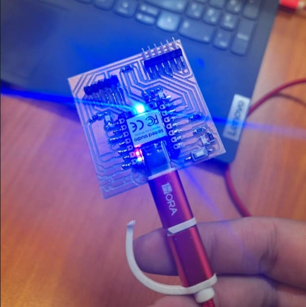
- Once it was completely soldered, the method to test it was by connecting it and checking if the Xiao leds turned on. If they did, it meant it worked, if not, the instruction we had was to disconnect it immediately. Also, the cable used was a USB-C type
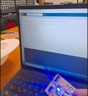
- The next step was to program the board, to make the other leds work. To do so I downoladed Arduino and opened a document provided by my FAB. There I looked for the Xiao's code online and added to my code. I also connected the PCB to the computer. Once there, I clicked on the verify option
- I had to wait first, it had to load, but then I clicked on the run option on the arrow pointing to the right. It was supposed to work and load the program to the PCB board, but it didn't work the first time, so I disconnected and repeated the process once more. That time It worked.
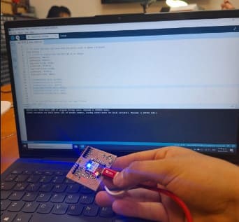
- Having my board programmed, it was supposed to light two other leds on it's own and the other one every time I pressed the button, but It didn't work, the only light that worked was the one in the Xiao still.
- I wasn't sure why this wasn't working, but a friend told me to add more solder to the xiao because that could be the problem. Once I did I repeated the programming process once again.
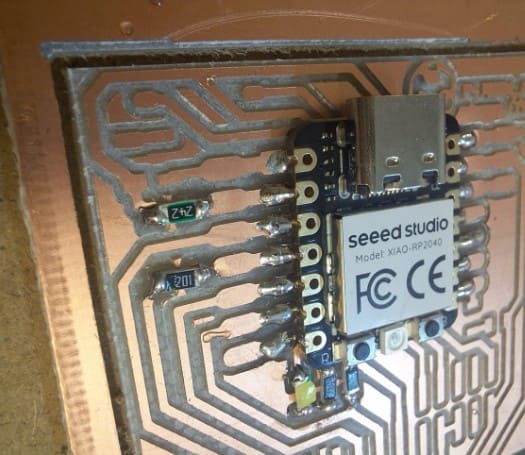
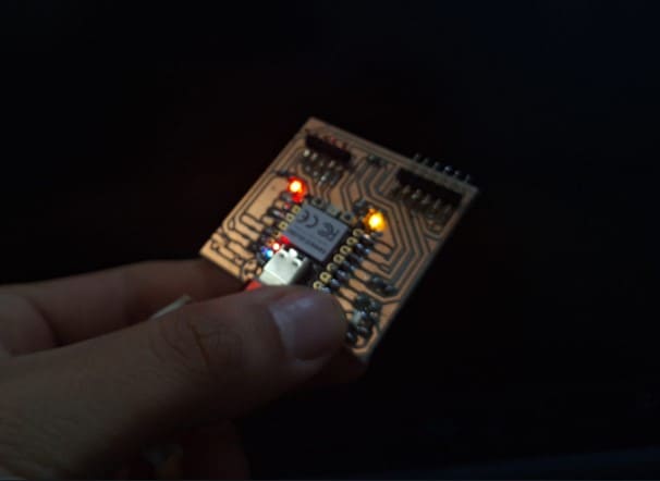
- There was the time for the truth: I connected it and this time the two intermitent leds worked! The only one I needed now was the led that depended on the button. I must have solved the problem with the amount of solder only, because this time my PCB worked!

To turn them into files the machine could process and cut I opened them on Mods Project. This is a free site where you can charge your files, It even has the model of the machine I would be using, so it was very helpful. To transform the PNGs I followed this process:
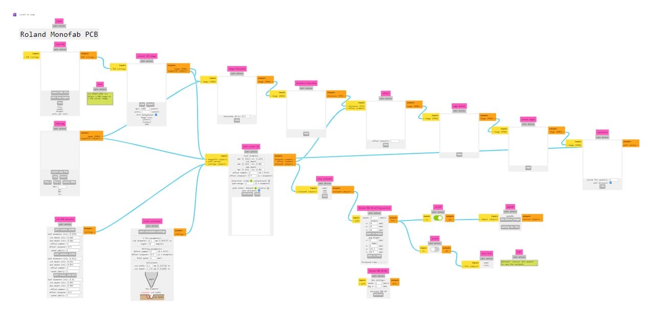
---- Using the machine ----
---- Soldering----
---- How to know if you did it well or there was a mistake?----
---- Programming the PCB----
It's aliveeee!
Final Shots!
Description for Image 1