WEEK 11
INPUT DEVICES
What is an Input?
As I understand it, it is a form in which data comes in from the outside and is converted into a form in which it can be interpreted according to the programming language. My easiest example to understand it is a button, when you press a button it interprets it as a signal, then receives and responds by converting the signal into programming language to actuate something. To learn more about inputs I invite you to view this week's group assignment here.
What did I do?
This week I used a light sensor, and a proximity sensor, both made by me during this week, because they are very easy to manufacture (they said), well actually they are, I only had some problems in the production, but let's start with the beginning...
LIGHT SENSOR
What is it and how does it work?
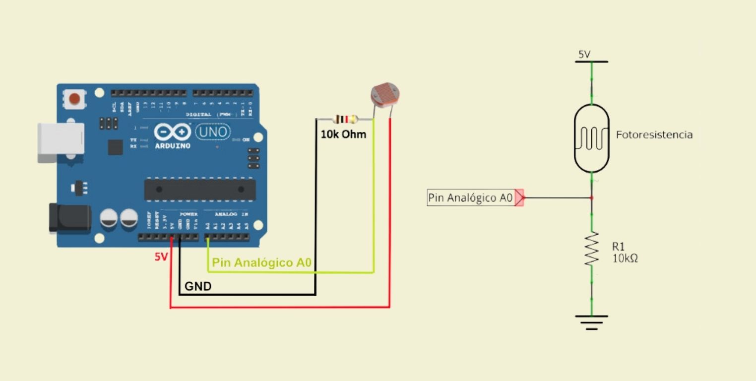
The light sensor (LDR or phototransistor) is a resistor whose function varies according to the amount of light that it perceives on its surface, activating functions when the intensity is higher, or vice versa, when it captures less light.
It is connected to a voltage divider, with one end connected to 5V, the other end connected to a resistor and ground (GND), and the center point of the voltage divider is connected to an analog input.
Design
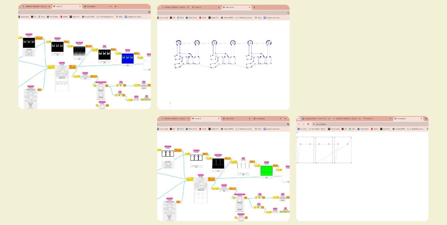
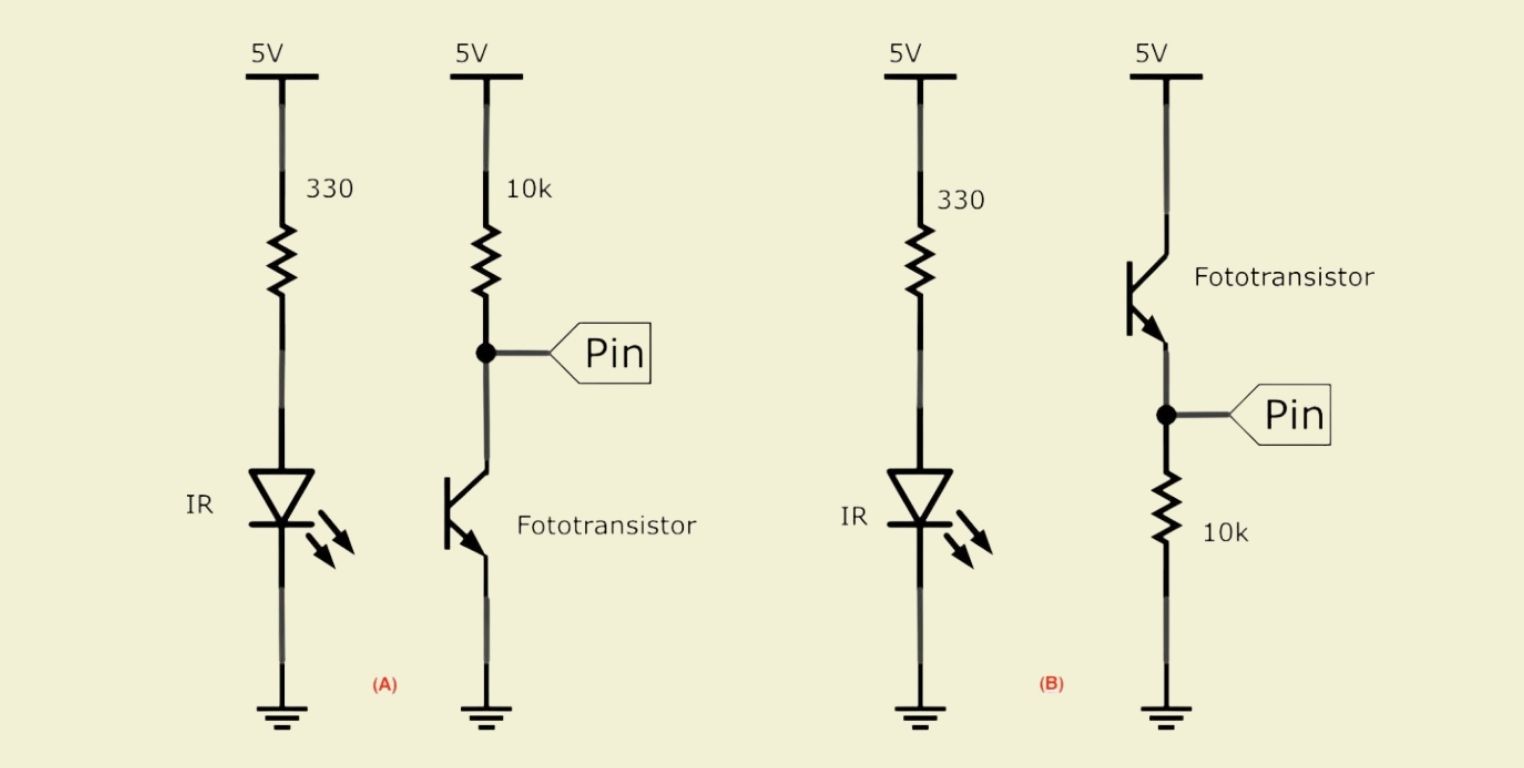
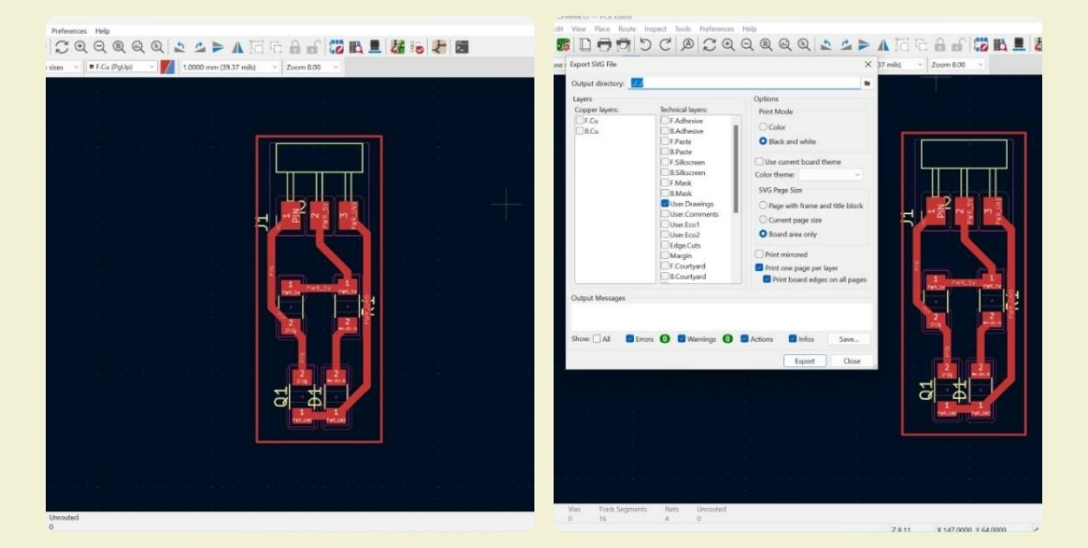
I based from the follow basic diagrams to showed in KiCad.
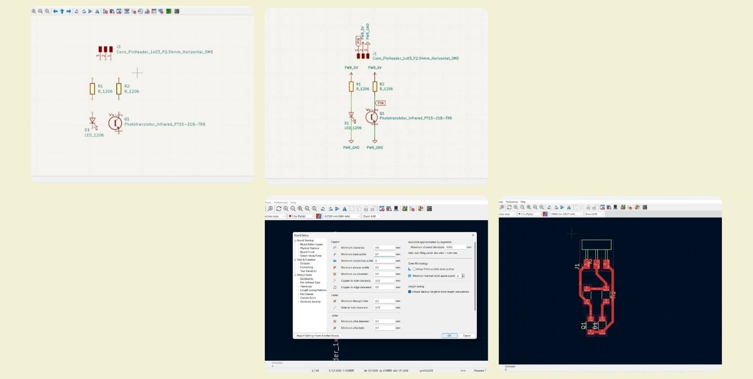
Actually, it was very simple, since it was a matter of finding the components and the traces in the program, in this case only a resistor, the phototransistor and 3 pins were needed. I connected them and verified that there were no errors, for this I also verified the size of the line, that it was the corresponding so that it was not so thin.
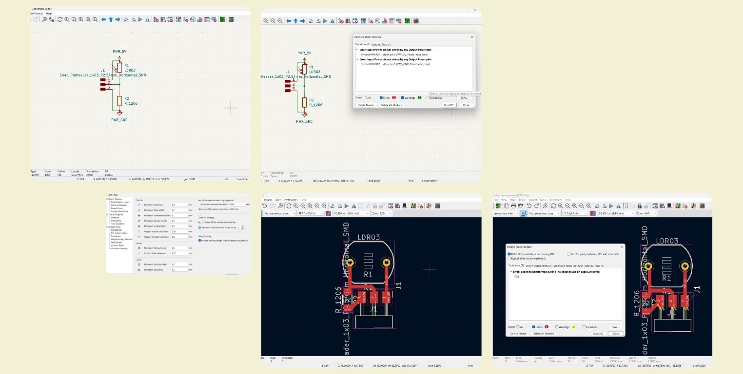
Then I drew the cutting rectangle, and I changed the thickness to 1.1 mm, this as a recommendation that an instructor gave me some time ago to ensure that the cut was done without problems. And as mistakes sometimes happen, I made more than 1. And as in the phototransistor footprint there was a hole, I selected the section and changed it to the stroke layer, so I didn't cut it as such.
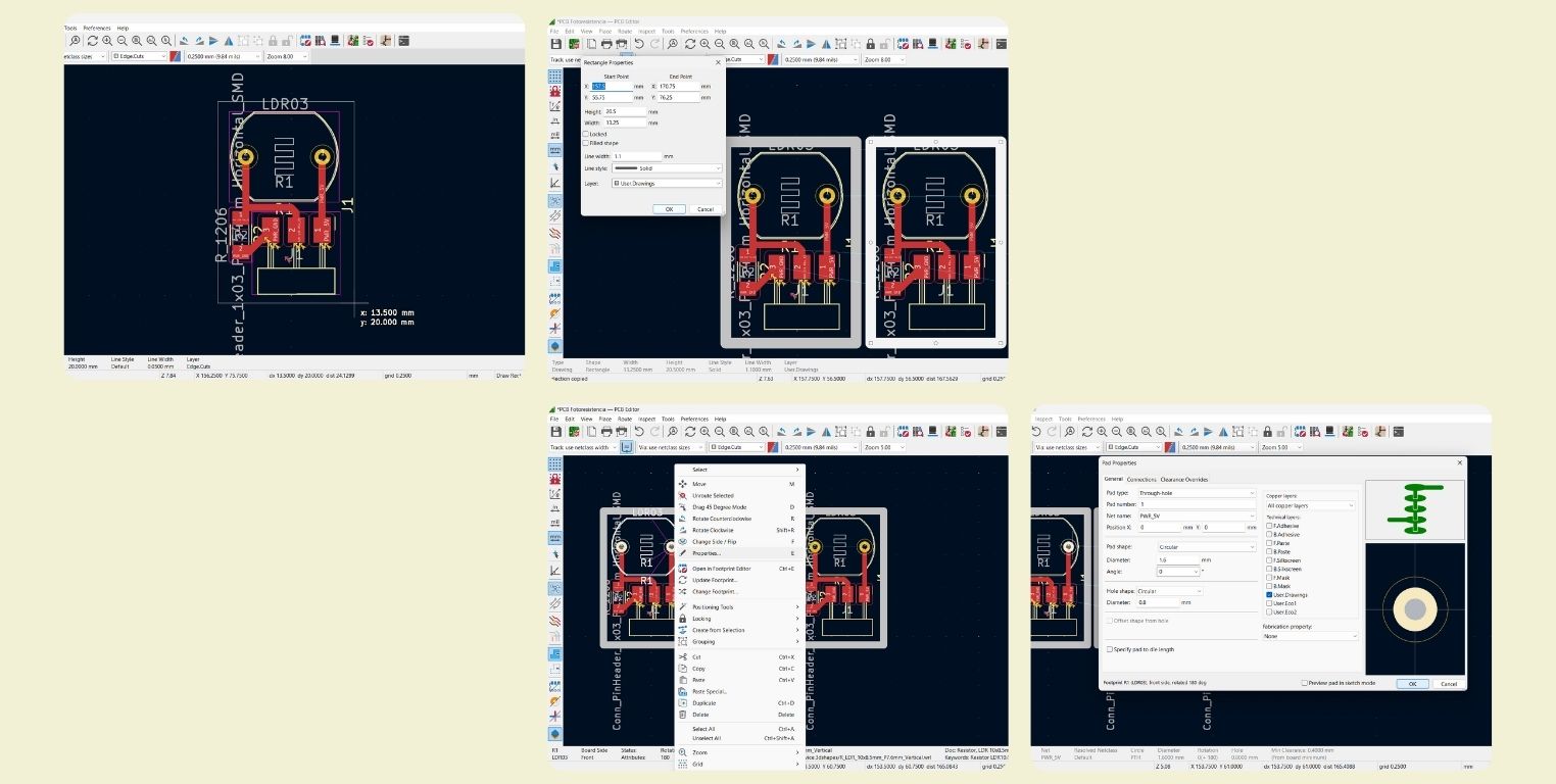
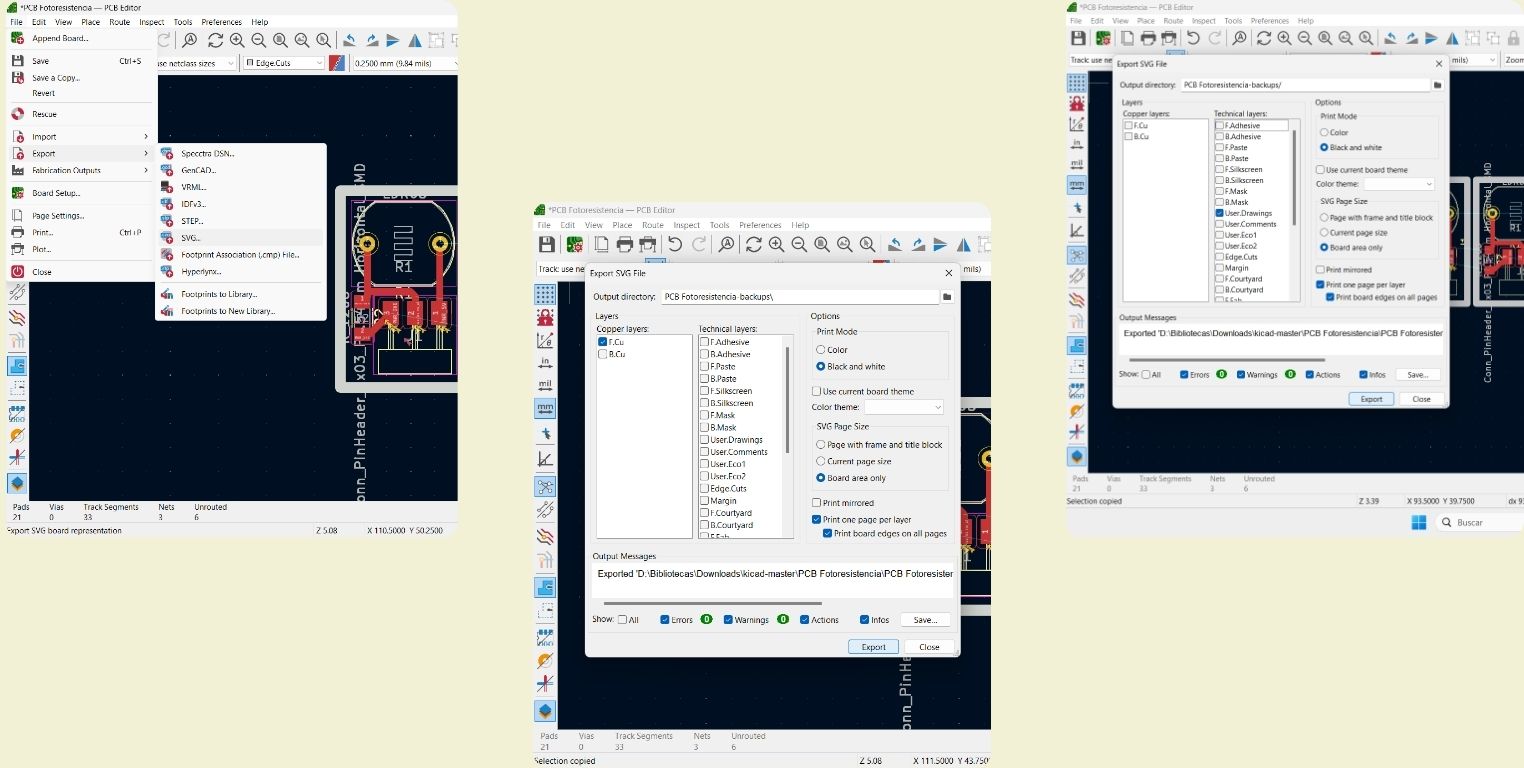
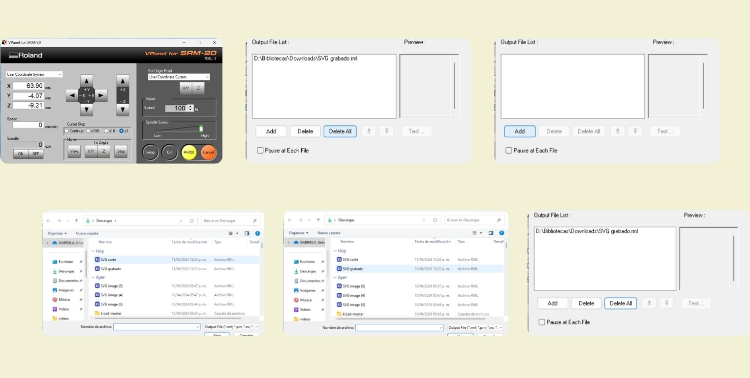
I saved the SVG files, stroke and cut separately to pass them through Mods.
Fabrication
To know more about this procedure I invite you to review the documentation of my week 8, where I explain the step by step. But basically what I did was to upload the file of the strokes, invert the color, then set the number of passes and thickness of the stroke; while for the cutting I didn't need to invert, I just set the number of passes and thickness of the cut. Something super important that I have to mention, is that I forgot to set the start at 0, then, although I marked the 0 in V-Panel in a coordinate, the cut started approximately 1 cm above, I learned for the future.
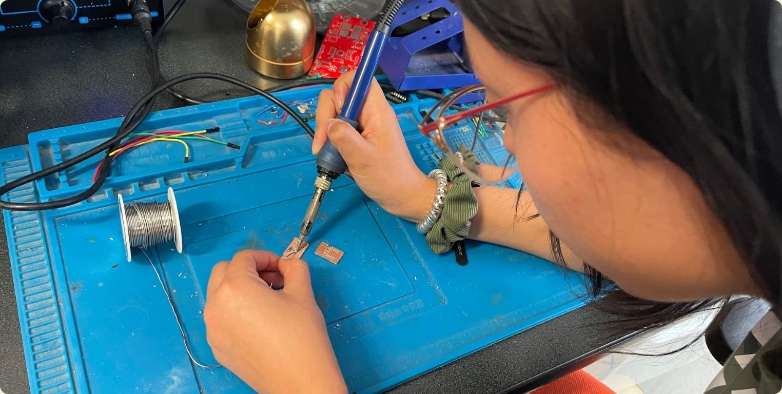
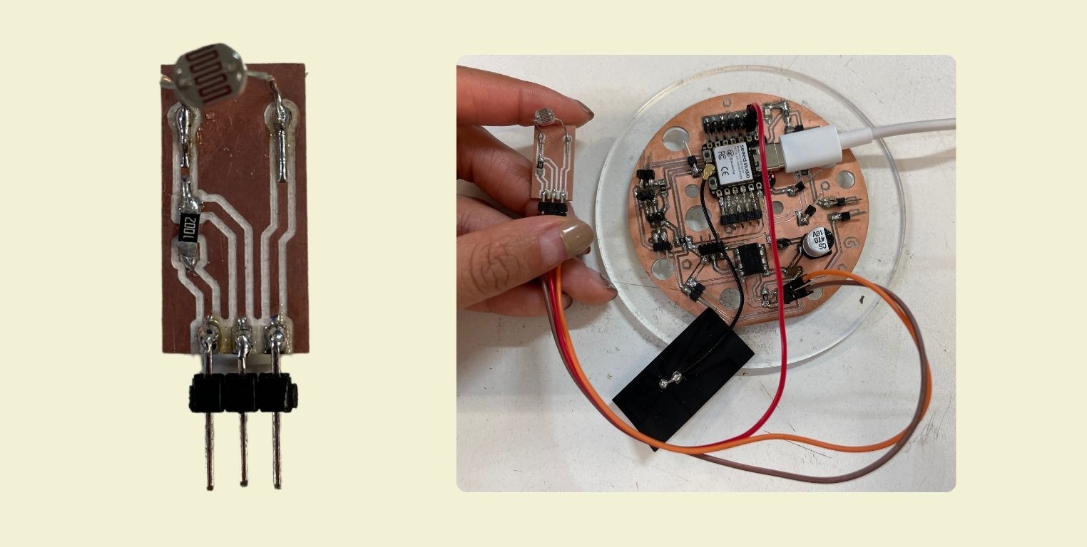
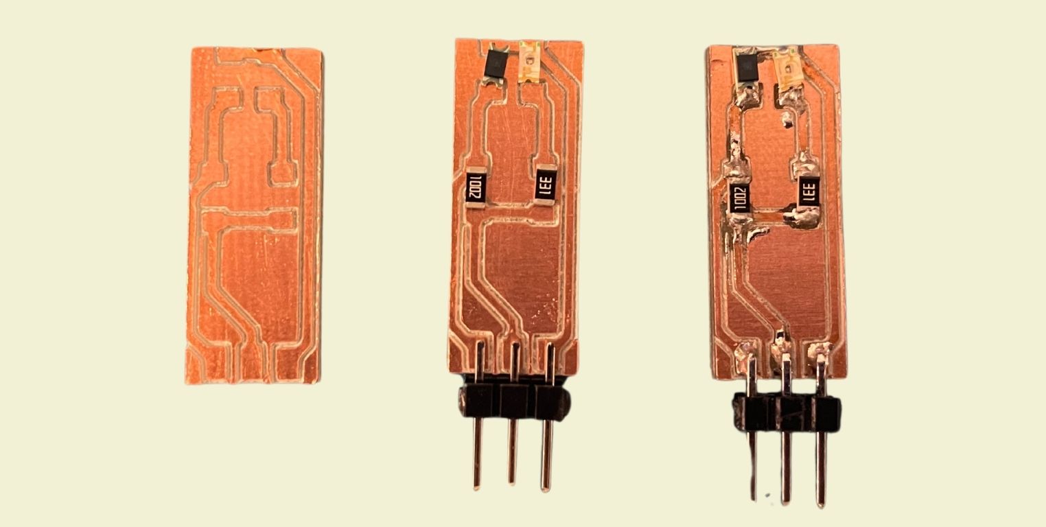
After cutting comes my favorite part, soldering each of the components
Once ready I connected it to the XIAO ESP32C3, and as it only has 3 pins it is very simple, one goes to ground, one to voltage and the other to signal.
Programming
Sometime a professor told me that the less pins, the easier to program, and at the beginning I didn't believe him at all, until I started programming this particular sensor. What I wanted to achieve is that when it detects that there is no light, it turns on, and when it detects light, it turns off.
First I defined the pins to which the sensor D1 would be connected, the led in D0 and finally thershold = 500 as the minimum analog value for the led to turn on.
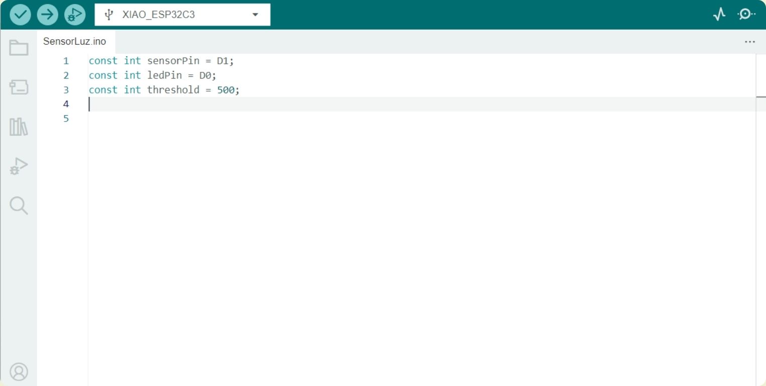
In the void setup function I configured the ledPin as output and the sensorPin as input, besides giving a 9600 baud communication to print data.
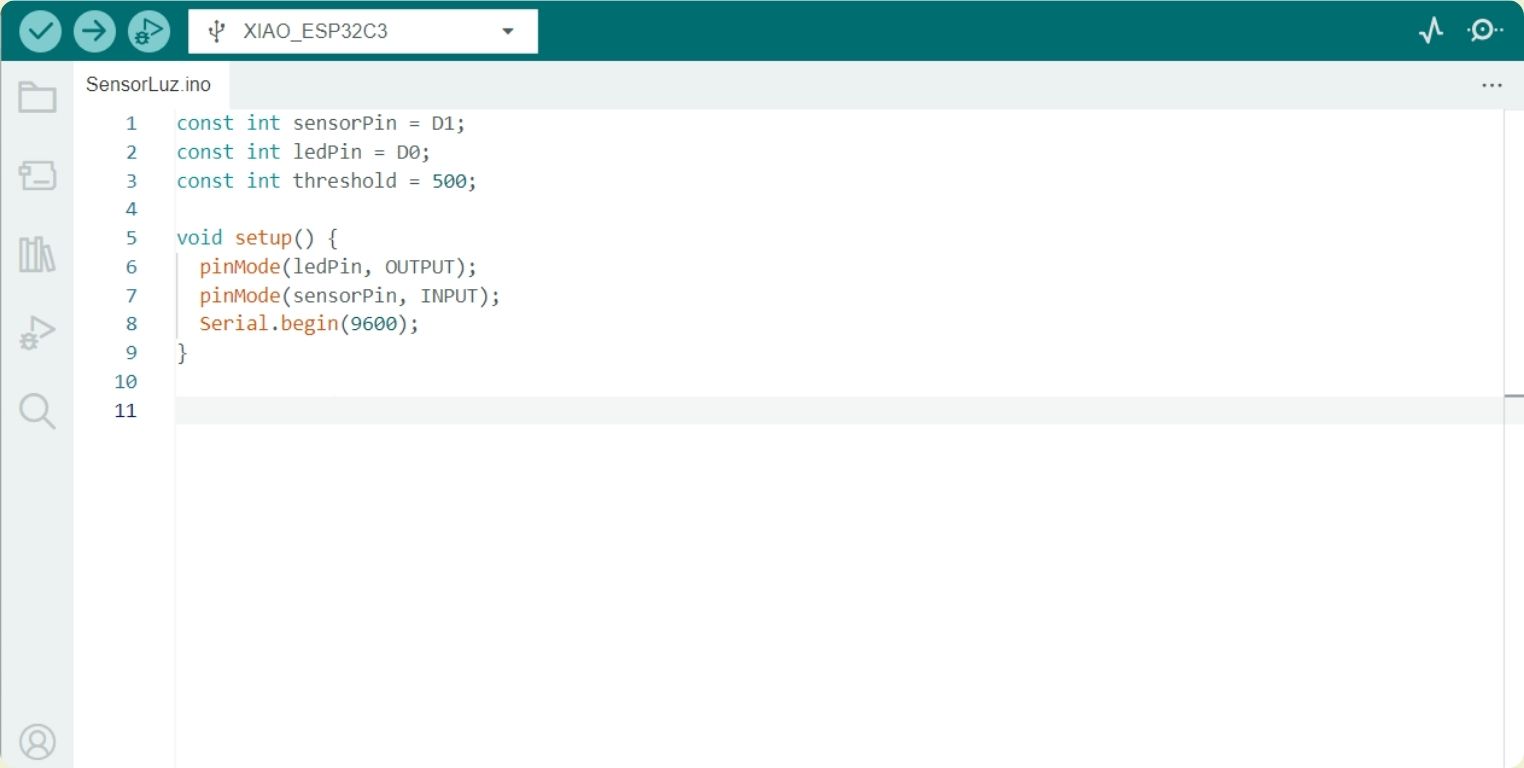
Finally, in the void loop function I told it to read the analog value of the pin, and according to what it read, if the amount of light was less, it would turn on the led, while if it was more, it would turn it off. I also included a delay to avoid fast reading problems with the sensor.
PROXIMITY SENSOR
What is it and how does it work?
This type of sensor can detect the proximity of elements within its detection field. In the case of the optical ones, like the one I will be using, they use infrared or visible light to detect this presence.
This is connected like the previous one, to a positive power supply, to ground and to an output to the microcontroller to define the signal.
Design
For this sensor my guide were the diagrams below, I know that surely there are some more complex, but considering that I was going to do it from 0, I looked for something simple to replicate and in which I had almost the minimum percentage of error.
The next step was to find the components in KiCad and connect them together according to the diagram above. I always check the size of the tracks so that they are not so thin and I don't have trouble soldering them.
Once ready I saved the files for tracing and cutting in SVG.
Fabrication
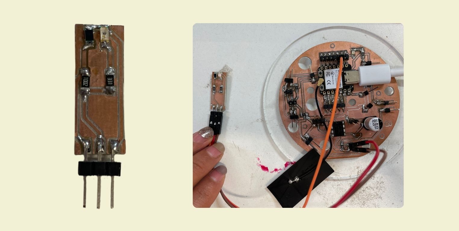
After going through Mods and cutting on the Roland SRM- mill machine, the next thing was to arrange the components on the future sensor and solder them.
This is how I connected the sensor to the XIAO ESP23C3.
Programming
The programming was fairly simple, I was looking for when I approached the sensor it would turn on, while if I moved away or detected nothing then it would stay off.
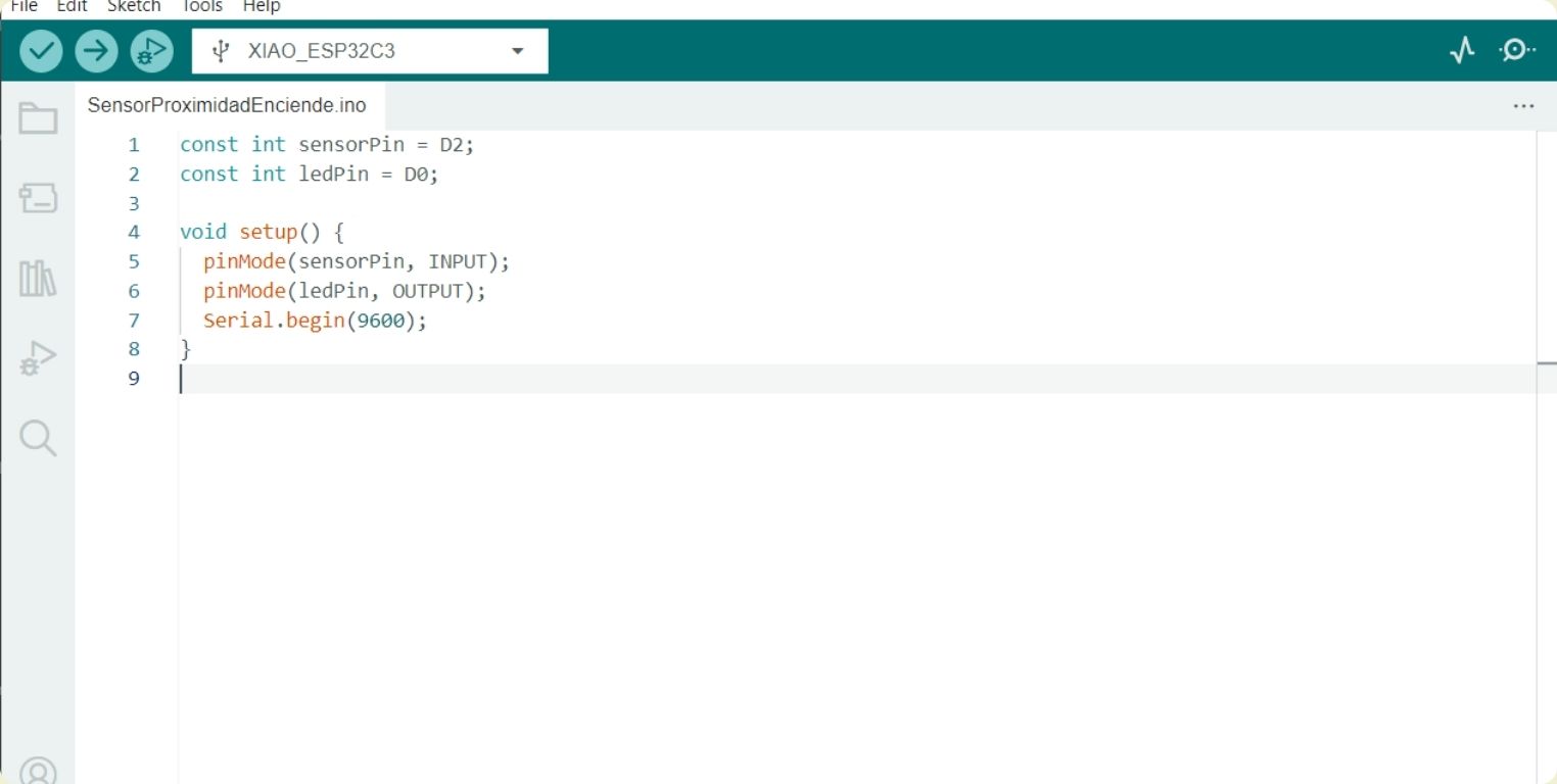
First I defined the pin location to which the sensor would be connected (at first I used D1, but it didn't work, so I changed to D2, but I'll explain later) and the pin to which the led would be connected, which doesn't change, is D0.
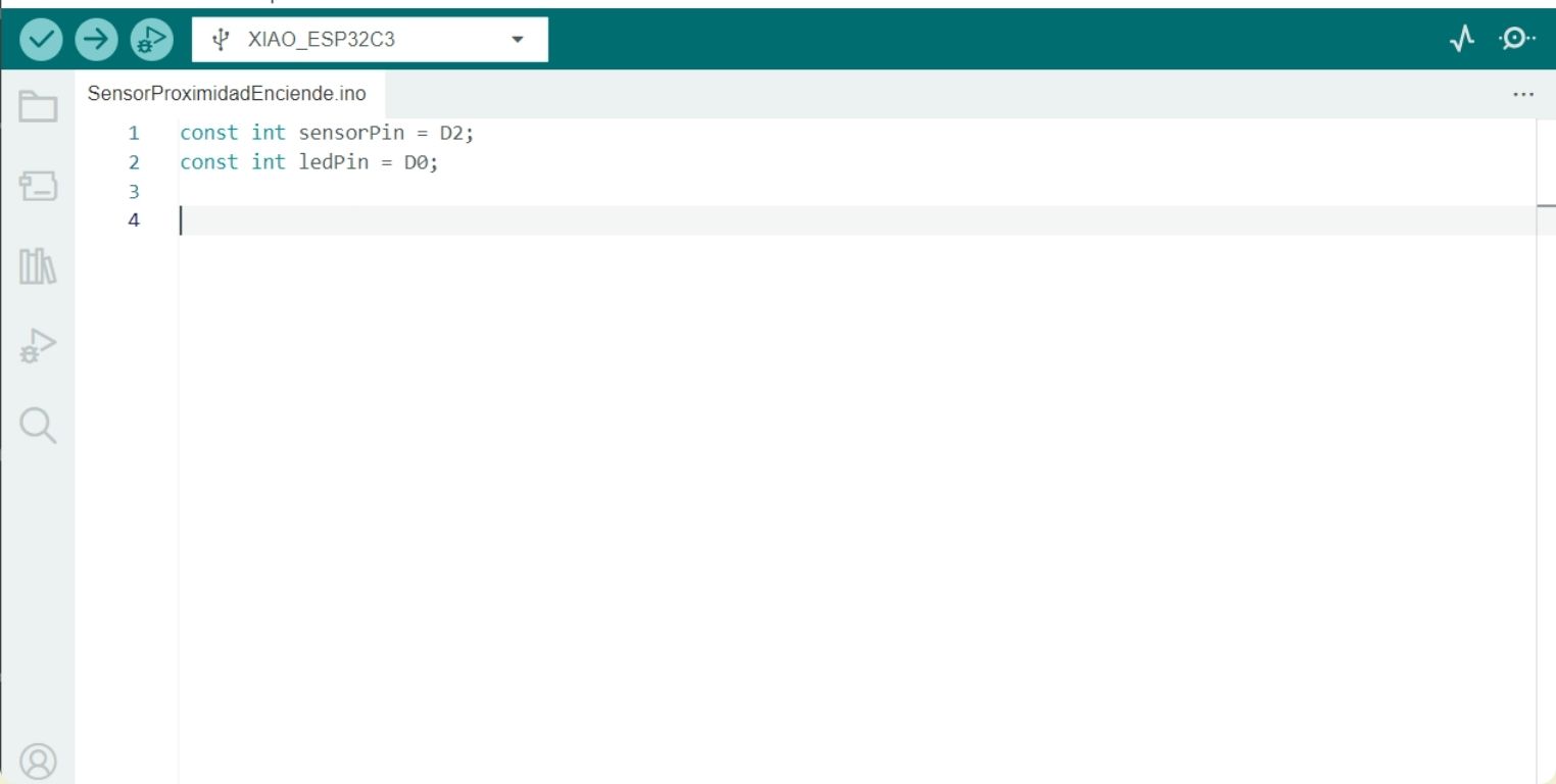
In void setup I defined the sensor as an input and the led as an output. I also added 9600 baud serial communication.
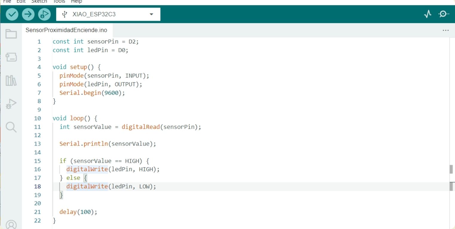
And in void loop I gave the indication that as long as the sensor detects something, the led turns on, while if, on the contrary, it does not detect anything nearby then it turns off.
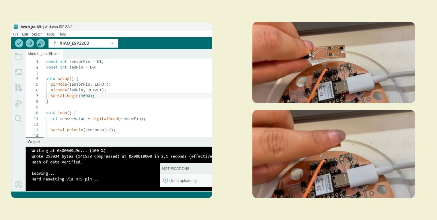
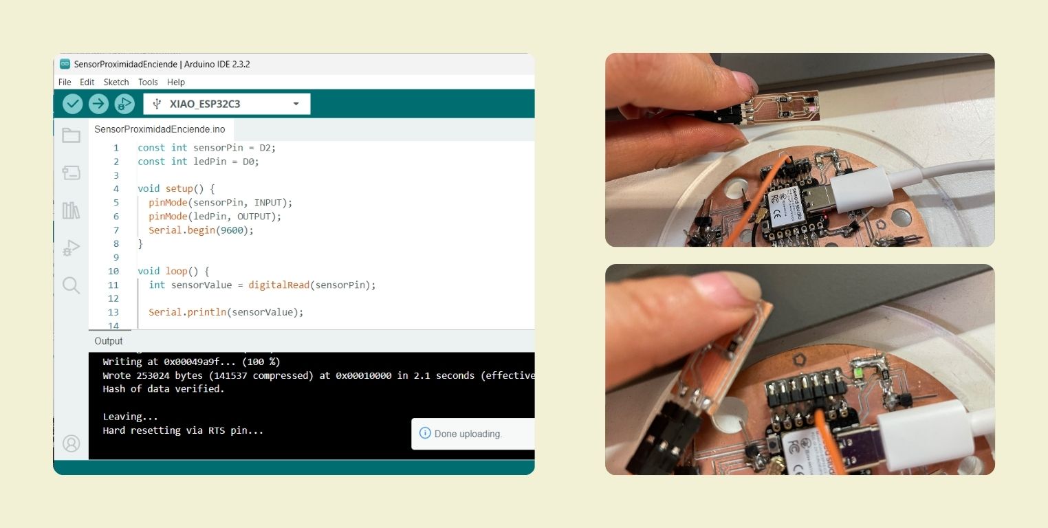
This was the first test I did, but it didn't work, it seemed to do nothing. At that point I checked the code, but found nothing strange, so I thought it was the sensor that was not working.
To rule out that it was the sensor I sent it a code to tell me on the serial monitor if it detected something or not, and it did. Special thanks to my friend Fer, who gave me this code to rule out that it was not the sensor.
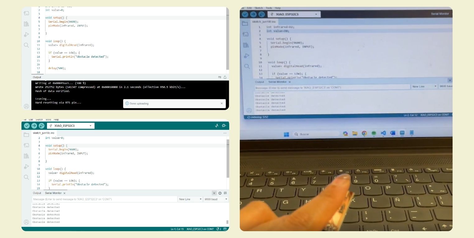
It was then that I asked Chat GPT what was wrong, and within the list of possible errors that I could have, I was discarding and finally tried to change the pin to which the sensor was connected, I still do not explain well, I think it's because I have a button connected to D1, I did not work well the code, when I changed to D2 worked!
Conclusion
I discovered that sensors are something that fascinate me, playing with them to see how they interact is great, I wish I could have had more time to do it. I was also looking for a way to test turning my final project on and off, I'm still not sure if I'll use either of these or go for the more boring one button option, but so far I've enjoyed experimenting with these two.