Electronic circuit and PCBs
Electronic circuit design on protoboard
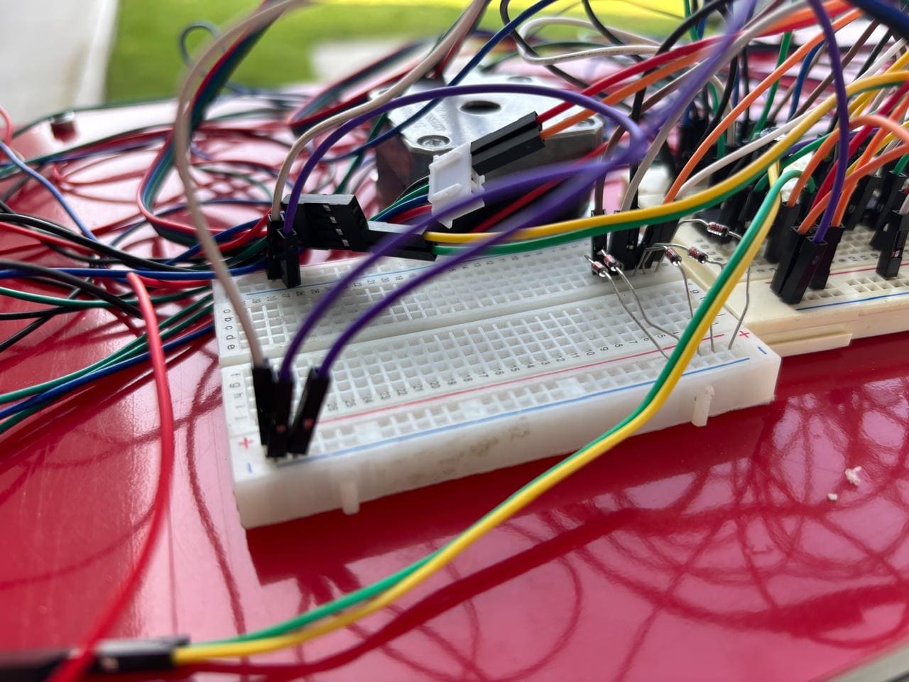
The development of this system began with circuit prototyping on a breadboard. This initial phase allowed for testing and verification of the component connections and data flows before proceeding with the final design on PCBs. The transition to custom-designed PCBs provided a compact and reliable layout tailored to the specific needs of the project, enabling efficient signal processing and data management.
Each PCB was created to handle specific functions, from reading voltage levels generated by the propellers to facilitating data transmission through the XIAO ESP32C3 module. The system’s core functionality relies on monitoring and transmitting data, which is essential for evaluating the performance of each propeller in real-time.
Testing the Circuit on the Protoboard
In the development of this project, the circuit was initially tested and adjusted on a protoboard. This stage was essential for validating the functionality of components, verifying proper connection layouts, and ensuring accurate data flow. Prototyping on a protoboard allowed for quick modifications, facilitating configuration adjustments before moving to the PCB fabrication stage.
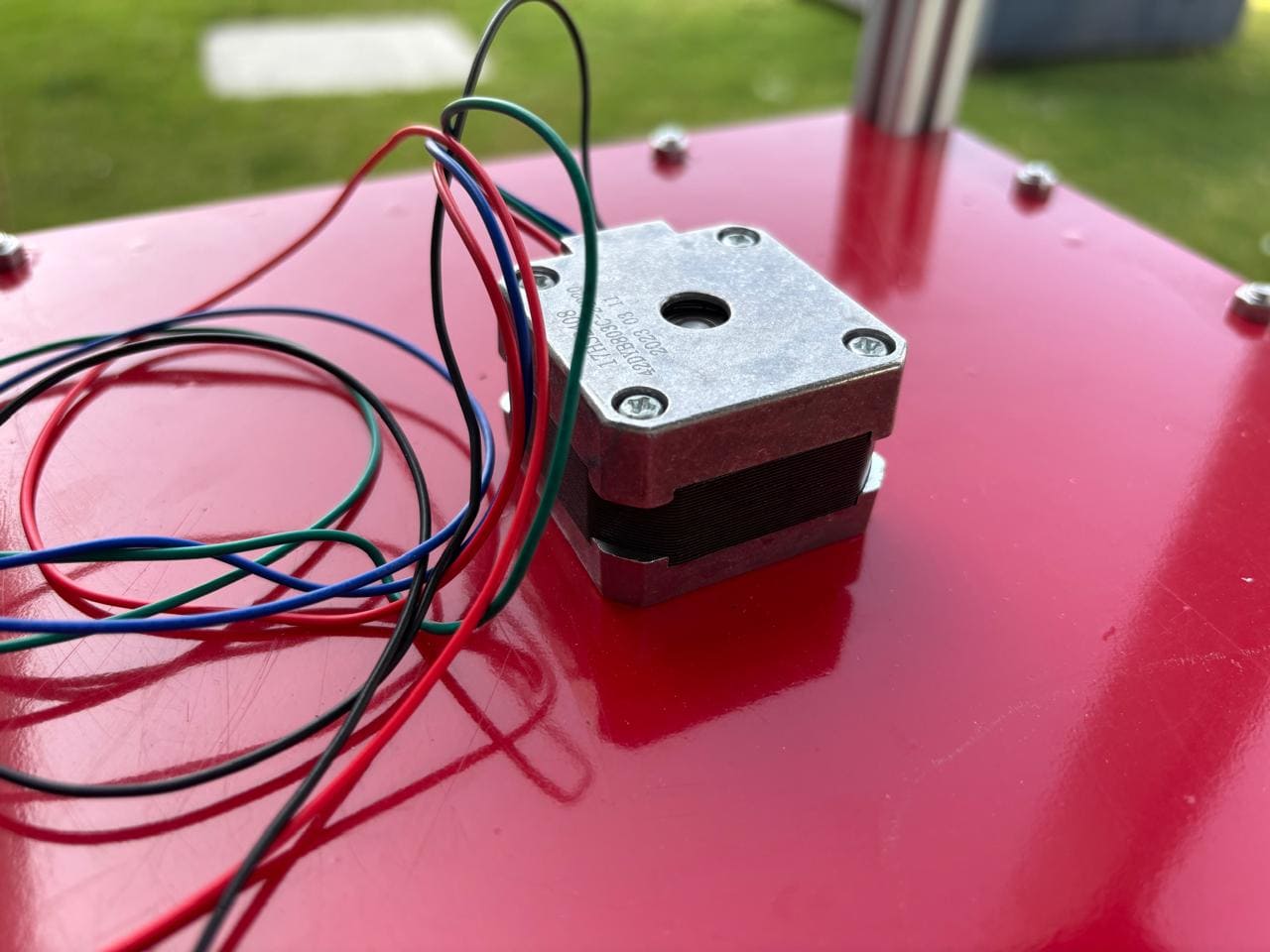
Component Setup and Configuration
All necessary components were placed on the protoboard, including the ATTiny85 microcontrollers, XIAO ESP32C3 module, capacitors, diodes, resistors, and jumpers. These elements were strategically arranged on the protoboard to simulate the final design, ensuring that all components functioned together effectively.
Main Challenge: Cable Complexity
A significant challenge during the protoboard setup was the number of wires required to connect each component. This large number of connections created a visually complex layout and made it difficult to trace signal routes. Special attention was needed to avoid connection errors and accidental short circuits. Additionally, the cable complexity occasionally led to interference, which could disrupt the I2C communication between the ATTiny85 and the ESP32C3.
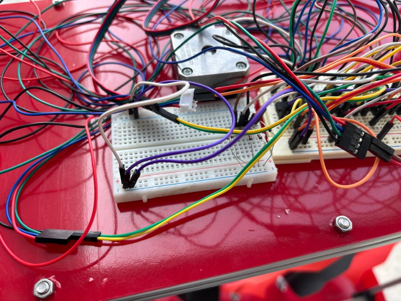
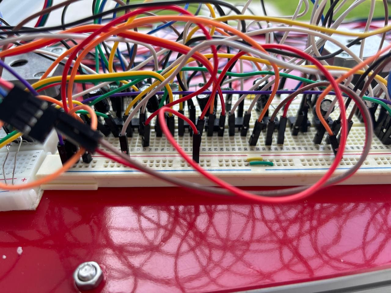
Interference Issues and Accuracy Measures
Interference in the connections, due to the excessive wiring and component proximity, was identified as a recurring issue. Different layouts of wires and components on the protoboard were tested to reduce these effects. Additional diodes and resistors were integrated to protect the circuit and improve the accuracy of voltage readings.
Optimization for the Final PCB Design
After identifying and resolving issues on the protoboard, important decisions were made for the PCB design, such as using more efficient routing paths to reduce interference and arranging components to minimize cable usage. This optimization process facilitated a smoother transition to the KiCad design phase, where the improvements identified during protoboard testing were reflected.
Summary of the Protoboard Testing Phase
Testing on the protoboard was essential for understanding the system's needs and making necessary adjustments to the design. Despite the challenges presented by extensive wiring, this phase ensured the circuit’s reliability and functionality before moving to custom PCB fabrication, guaranteeing an optimized and precise design in the final product.
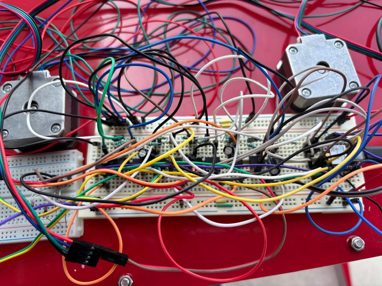
Components used
1. NEMA17 - Stepper motor
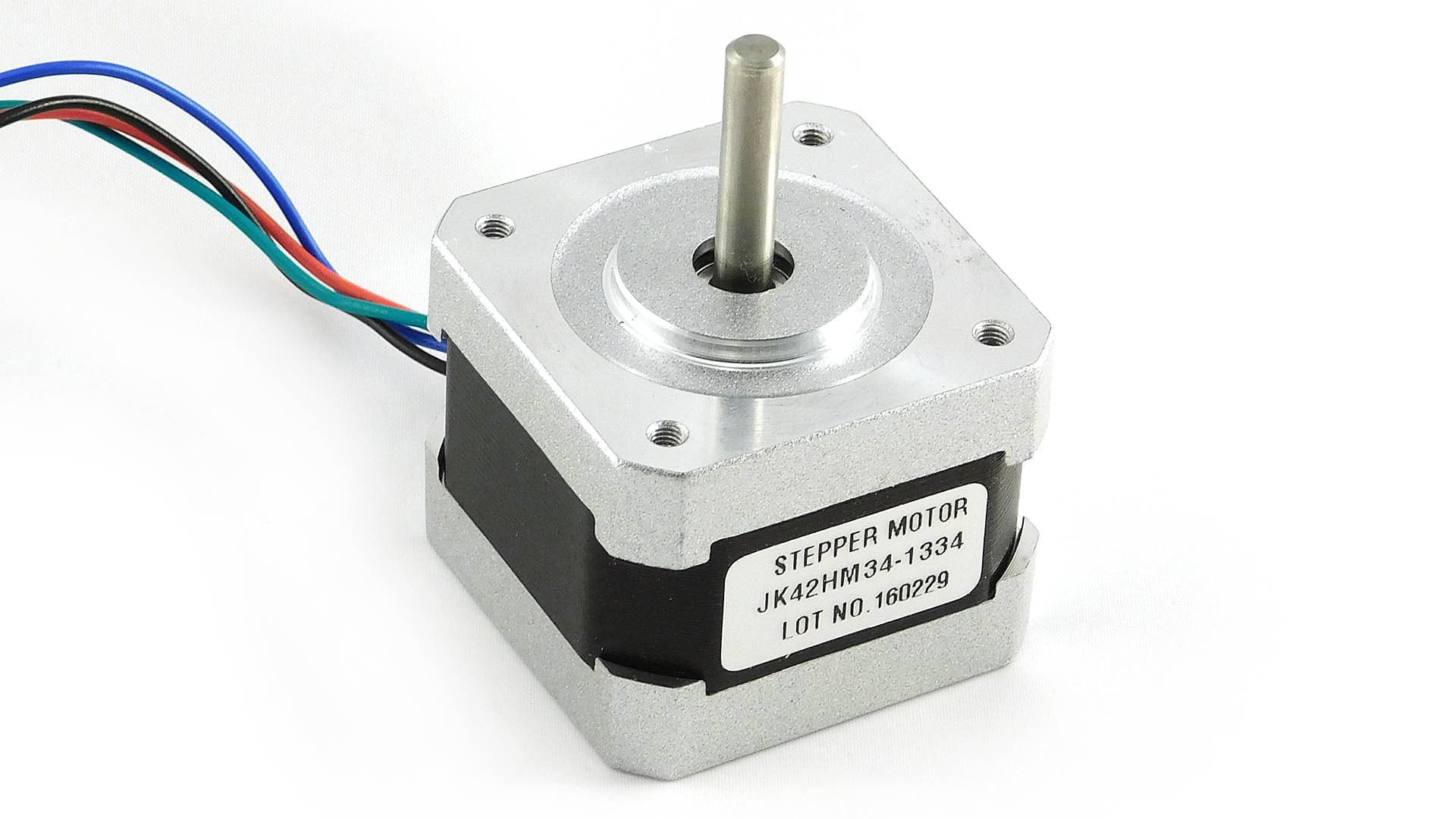
Description: A motor used to control the rotation of the wind turbine propellers accurately.
Specifications:
Torque
0.4 Nm
Current
1.2 A
Step Angle
1.8°
Voltage
12 V
2. 100 µF Electrolytic Capacitor
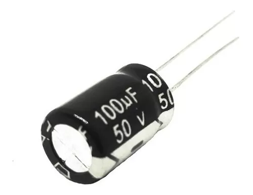
Description: Stabilizes voltage levels in the circuit and smoothens fluctuations caused by power surges.
Specifications:
Capacitance
100 µF
Tolerance
±20%
Maximum Voltage
25 V
Type
Electrolytic
3. 1N4148 Diode
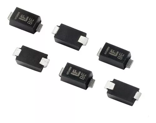
Description: A high-speed diode used to protect the circuit against overcurrent conditions.
Specifications:
Maximum Reverse Voltage
100 V
Maximum Forward Current
300 mA
Reverse Recovery Time
4 ns
4. Resistors
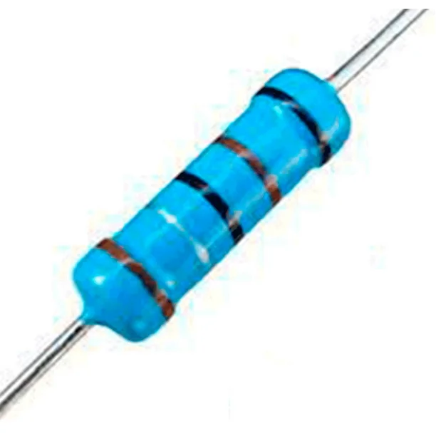
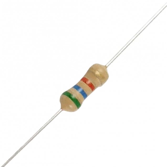
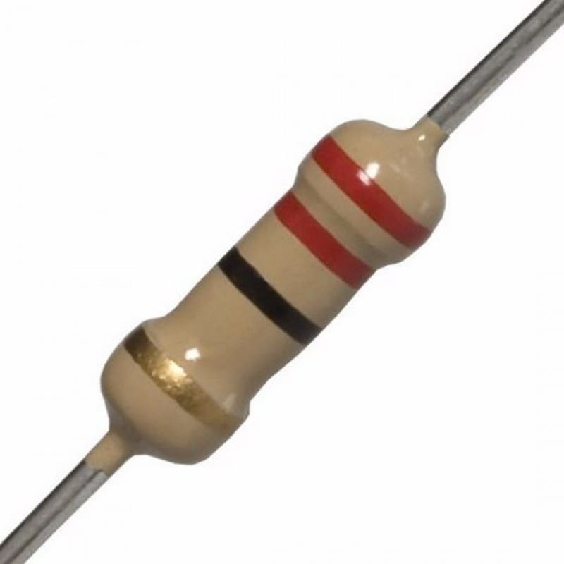
Description: Used across various parts of the circuit to control current and ensure stable operation of other components.
5. Jumpers
Description: Configurable connectors that allow hardware settings adjustments without additional soldering.
6. ATTiny85 Microcontroller
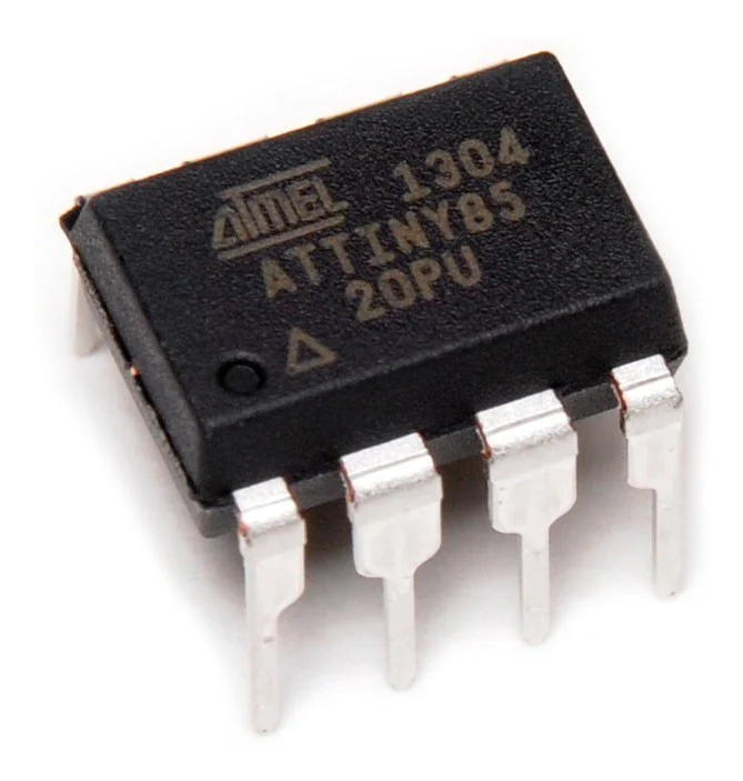
Description: A compact microcontroller responsible for reading sensor data and communicating through the I2C protocol.
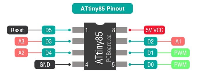
Specifications:
Flash Memory
8 KB
Operating Frequency
20 MHz
I/O Pins
6
Communication
I2C Support
Pinout:
7. XIAO ESP32C3
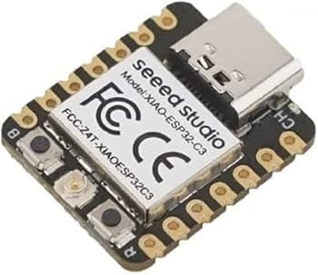
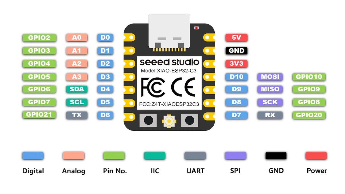
Description: A high-performance, low-power microcontroller that provides Wi-Fi and Bluetooth connectivity. The ESP32C3 acts as the main communication module, transmitting data from the ATTiny85 units to an online platform for real-time monitoring.
Specifications:
Processor
ESP32-C3 (RISC-V)
Memory
400 KB SRAM, 4 MB Flash
Connectivity
Wi-Fi and Bluetooth
Communication
I2C Support
Pinout:
Circuit Schematic Description

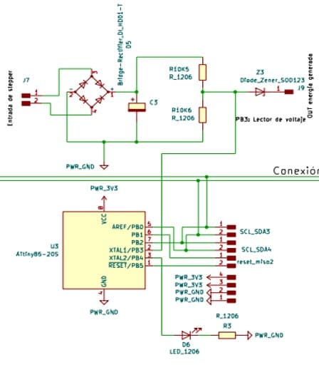
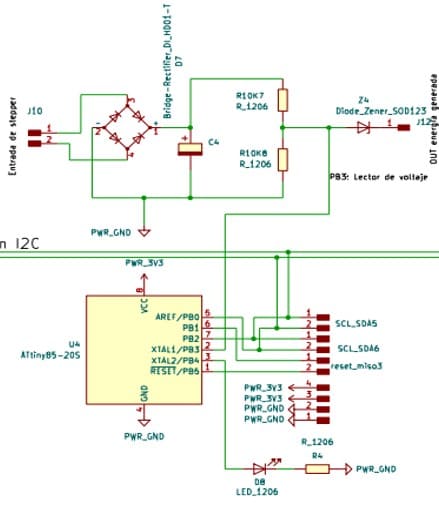
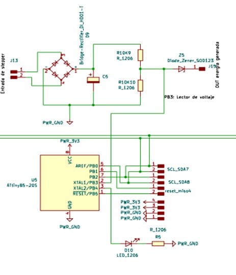
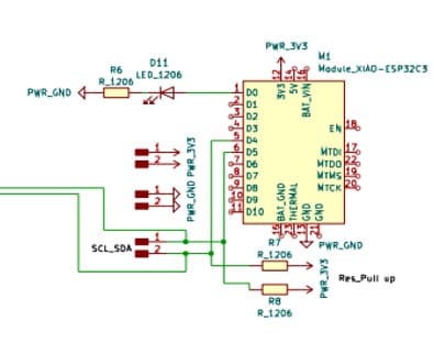
The first image shows the complete circuit schematic, with multiple ATTiny85 microcontrollers connected to the XIAO ESP32C3 via the I2C protocol. This layout allows each propeller's voltage data to be read and sent to the ESP32C3, which then transmits the data to an online platform where it can be displayed in a web application. This setup enables real-time monitoring of the power generated by each propeller, providing valuable insights into the system’s performance.
I2C Communication Protocol
The communication between the ATTiny85 microcontrollers and the ESP32C3 module is managed using the I2C protocol. This protocol allows multiple devices to share the same data bus with only two lines:
- SCL (Serial Clock Line): Synchronizes data transfer timing.
- SDA (Serial Data Line): Carries the actual data.
Each ATTiny85 acts as an I2C slave, responsible for gathering voltage data from its designated propeller. The ESP32C3 serves as the I2C master, requesting data from each ATTiny85 and then aggregating this data. Once collected, the ESP32C3 transmits the information over Wi-Fi to a web server, where the data is visualized through a web interface. This system enables remote monitoring, allowing users to see how much power each propeller is generating at any given time.
Circuit Operation
Power Input Stage
The circuit is powered by a stable 3.3V or 5V input source. Each PCB features capacitors and diodes for voltage stabilization and surge protection, ensuring consistent operation across all components.
Voltage
3.3V / 5V
Capacitors
100μF
Protection
Zener Diode
Voltage Measurement and ATTiny85 Microcontroller
Each ATTiny85 microcontroller is dedicated to a specific propeller, measuring the generated voltage and relaying data via I2C communication to the XIAO ESP32C3. The ATTiny85 gathers voltage data through a protected circuit with diodes and resistors to ensure accurate readings and shield against electrical noise.
Data Processing and Transmission by XIAO ESP32C3
The XIAO ESP32C3 functions as the central hub for data collection and transmission. It gathers data from each ATTiny85 via I2C and transmits this information over Wi-Fi to an online server. This server processes and displays the data, enabling real-time monitoring of the power generated by each propeller. The web interface provides users with insights into the turbine's efficiency and performance.
I2C Communication Protocol
The I2C communication protocol is used to connect multiple ATTiny85 microcontrollers with the XIAO ESP32C3. This setup allows the microcontrollers to act as slaves, sending data to the ESP32C3 master. I2C is efficient for this project because it simplifies wiring and enables scalable data collection from multiple sources.
KiCad
KiCad is an open-source electronic design software, widely used in electronic engineering for creating schematics and designing PCBs (Printed Circuit Boards). Its user-friendly interface and advanced features make it suitable for both simple and complex electronic projects.
In this project, KiCad played a crucial role in developing the PCBs required for the wind turbine system, allowing each propeller to measure and transmit its energy generation data in real-time. With KiCad, we were able to optimize the designs to ensure precision and functionality in data transmission to the communication module.
Designed PCBs
- 5 PCBs for ATTiny85: Each PCB is dedicated to an ATTiny85, which measures the voltage generated by an individual propeller. These PCBs enable independent data collection from each propeller, ensuring accuracy and consistency in power measurements.
- 1 PCB for XIAO ESP32C3: This board acts as the central hub, collecting data from the ATTiny85 microcontrollers and transmitting it over the Internet for remote monitoring. The XIAO ESP32C3 PCB is also responsible for managing power and establishing I2C communication with the other PCBs.
Design Process in KiCad
Schematic Creation
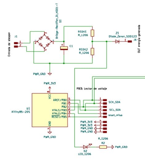
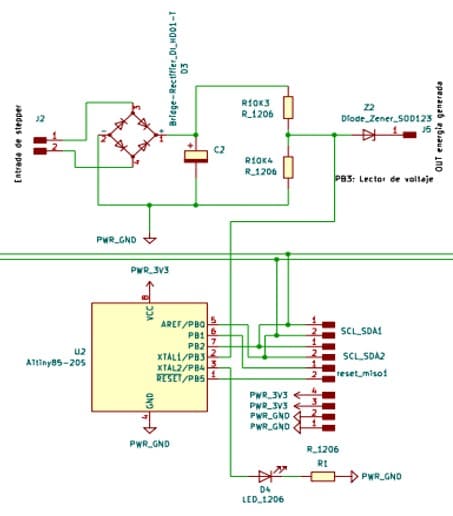
The design process begins with creating an electrical schematic, where all necessary components are placed and connected, including resistors, capacitors, diodes, ATTiny85 microcontrollers, and the XIAO ESP32C3 module.
The schematic provides an overview of the circuit, ensuring that each component is correctly connected. This phase is crucial, as an accurate schematic is the foundation for an error-free PCB design.
PCB Layout Design
Once the schematic is complete, the next step is the physical layout design of the PCB. In this phase, components are arranged within a limited space, optimizing the area of the board. The connections (traces) between components are routed to minimize distance and reduce interference, enhancing circuit efficiency.
Trace routing requires careful planning to avoid signal crossover or electromagnetic interference, which is especially important in communication circuits like I2C.
Manufacturing Optimization
In this stage, the design is optimized to facilitate the manufacturing process. This includes adjusting trace sizes, configuring mounting holes, and ensuring that the design complies with manufacturing requirements. Factors such as copper layer thickness, pad size for soldering, and trace spacing are considered, which all impact PCB reliability and durability.


Physical PCB Assembly
After completing the design and manufacturing processes, the physical PCBs were assembled to prepare them for integration into the wind turbine system. Each PCB is meticulously assembled and inspected to ensure all components are placed correctly, following the design specifications.
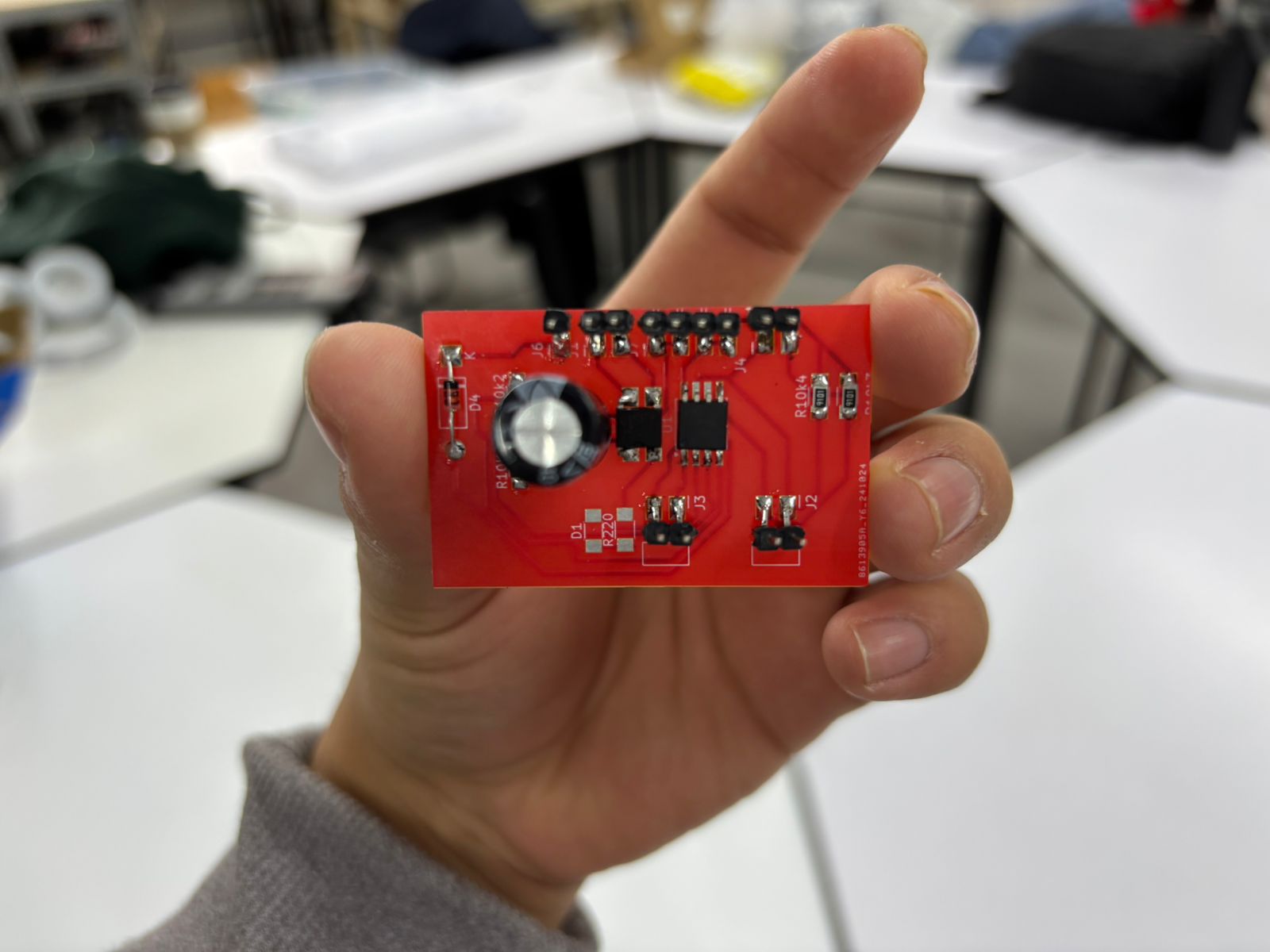
ATTiny85 PCB
This PCB is specifically designed to measure voltage generated by a single propeller and transmit data to the central ESP32C3 module.
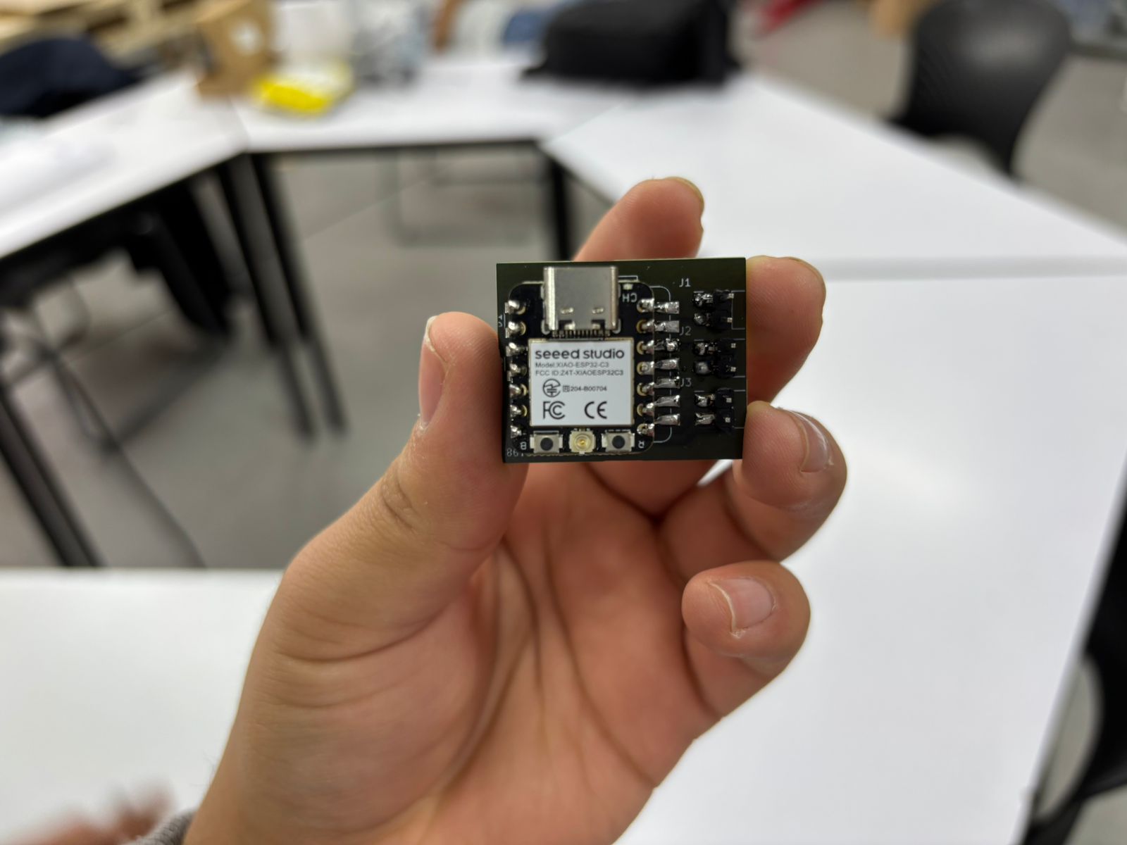
XIAO ESP32C3 PCB
This PCB functions as the central hub, receiving data from the ATTiny85 microcontrollers and transmitting it to the web server for remote monitoring.

