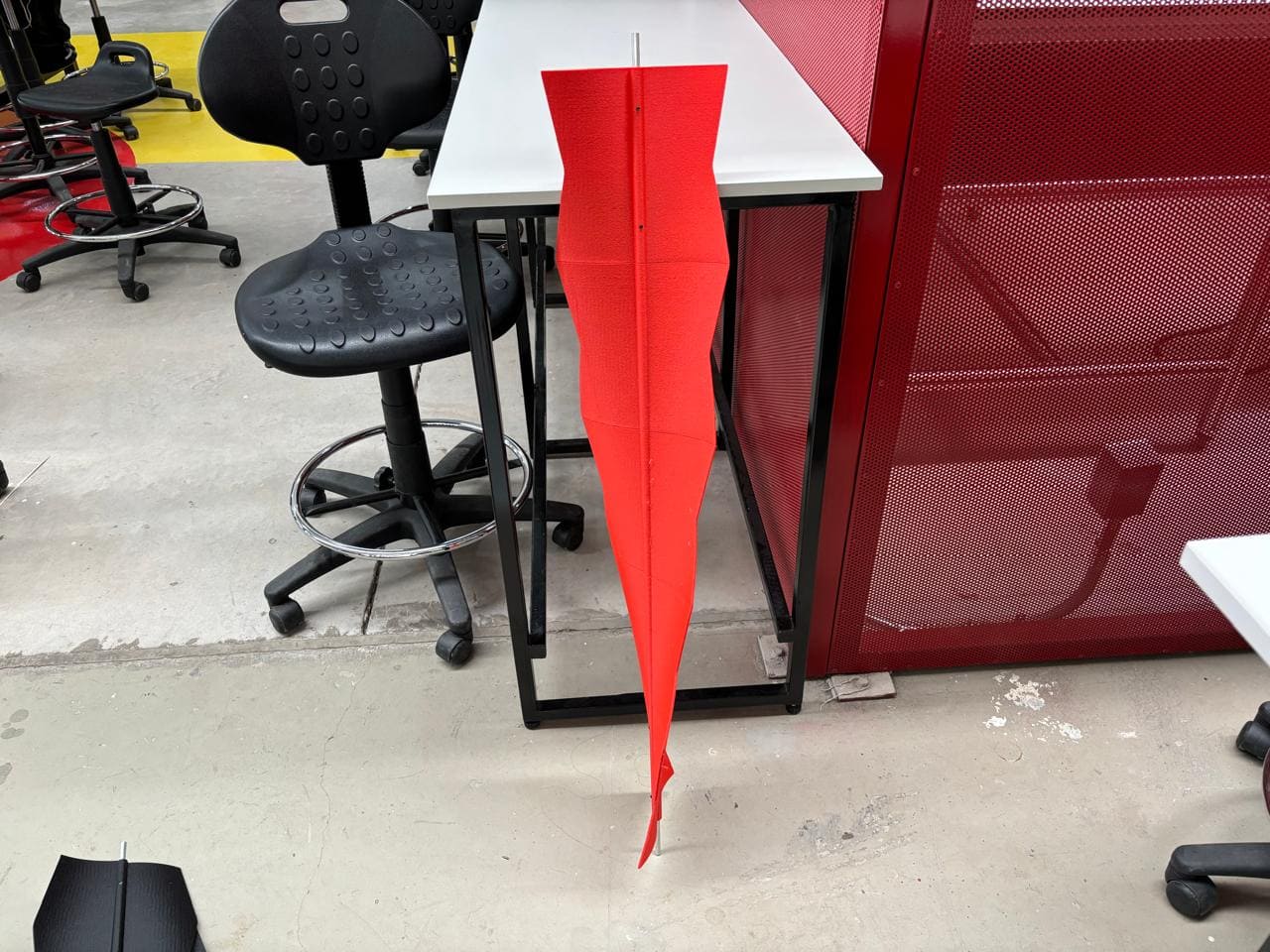
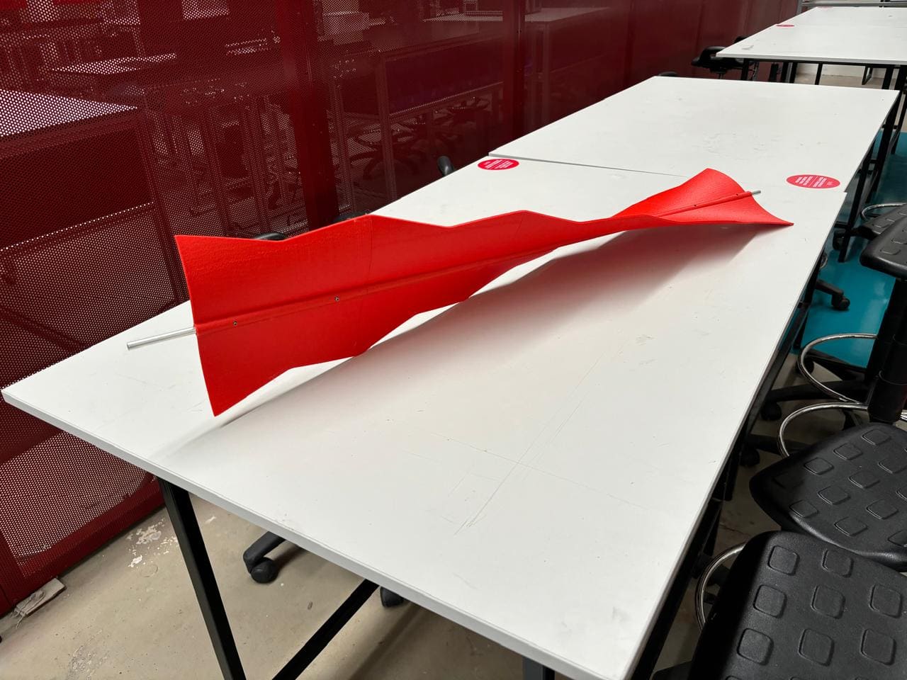
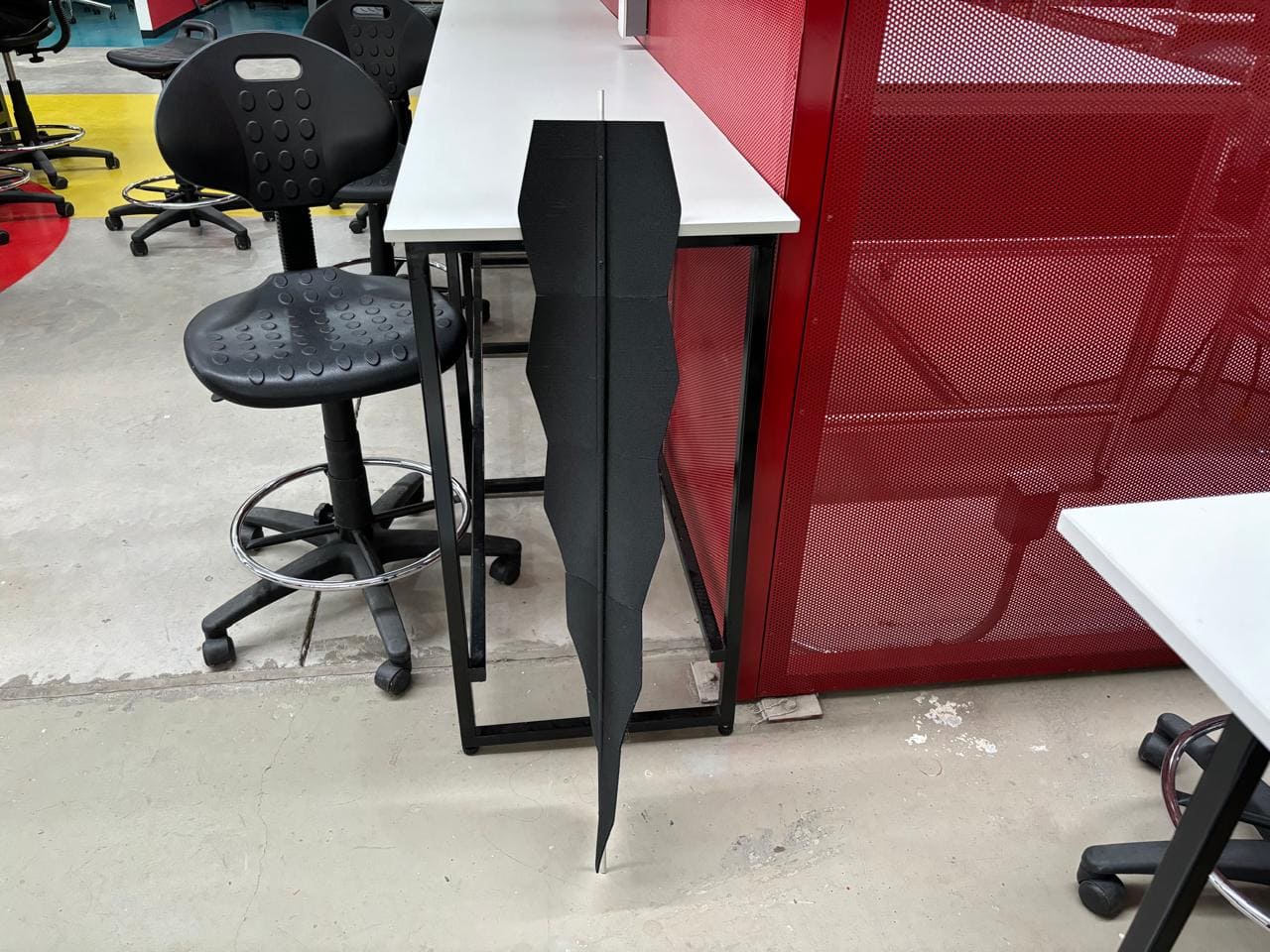
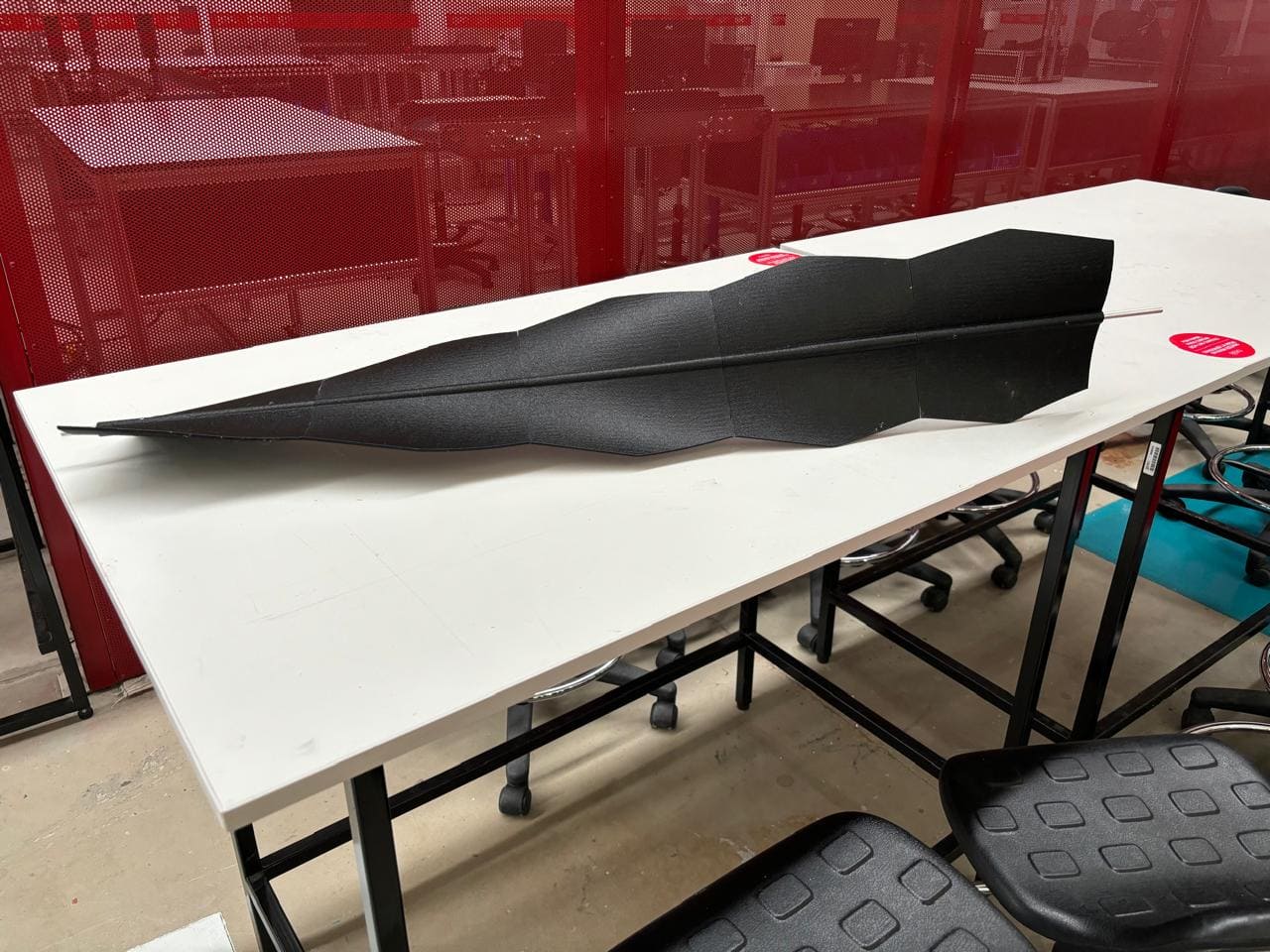
3D printing of propelleres
Design of the Wind Turbine Propellers
To design the propellers, a mood board was first created to gather ideas and establish the project's direction.
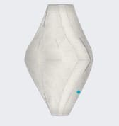
1st Proposal
This is an organic figure composed of four protruding blades, designed to optimize precision when receiving air.
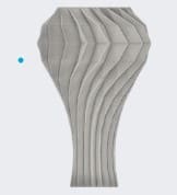
2nd Proposal
It has an appearance with multiple blades to try to maximize the wind capture.
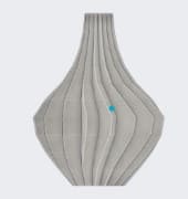
3rd Proposal
It presents a vase-like appearance, where the aim is to capture wind with its robust and slender design.
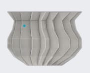
4th Proposal
This design not only improves wind capture efficiency but also represents an aesthetic and functional advancement with its star-shaped design.
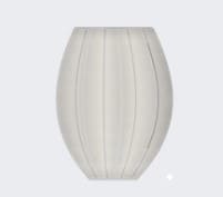
5th Proposal
By emulating the aerodynamics of leaves, our blades can capture the wind more efficiently, thus enhancing the overall performance of the wind system.
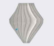
6th Proposal
Our design features a set of multiple blades, conceived to optimally harness the wind, even under minimal conditions.
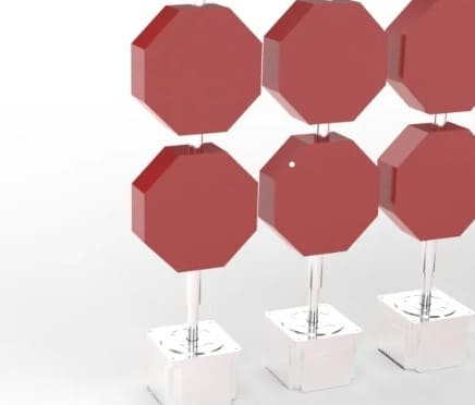
7th Proposal
Octagonal Blade
The mechanism consists of an 8mm diameter rod and a coupling.
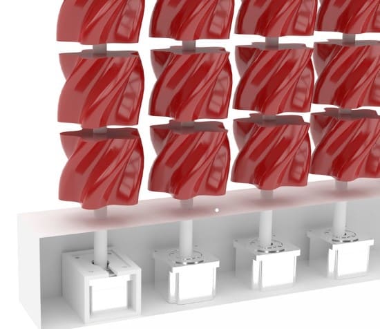
8th Proposal
Floral Blade
Cylindrical pentagon in the shape of a flower.
Proposals
Proposal 1

This proposal features a blade with a smooth, organic twist, characterized by wide, flowing curves along its length. Its aerodynamic design gradually narrows at both ends, optimizing wind capture with a consistent flow across its surface. The moderate twist angle of this blade allows it to function efficiently in stable wind conditions.
Propsal 2

In this second proposal, the blade has a more pronounced twist than the previous design, with sharp, defined lines that give it a thinner and more streamlined profile. This design, with a greater tilt, is intended to maximize energy capture in strong wind conditions. Its slender appearance also makes it ideal for dynamic wind contexts, where the blade can quickly respond to changes in wind speed.
Proposal 3
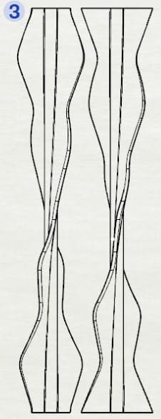
The third proposal stands out for its segmented design, with accentuated curvature changes that create a wavy pattern along its length. These multiple curves allow for better wind capture from various directions, making it versatile and adaptable. This blade is ideal for environments where the wind direction changes frequently, providing flexible and effective performance.
Final proposal
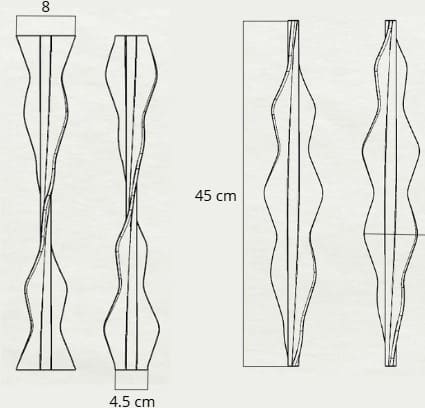
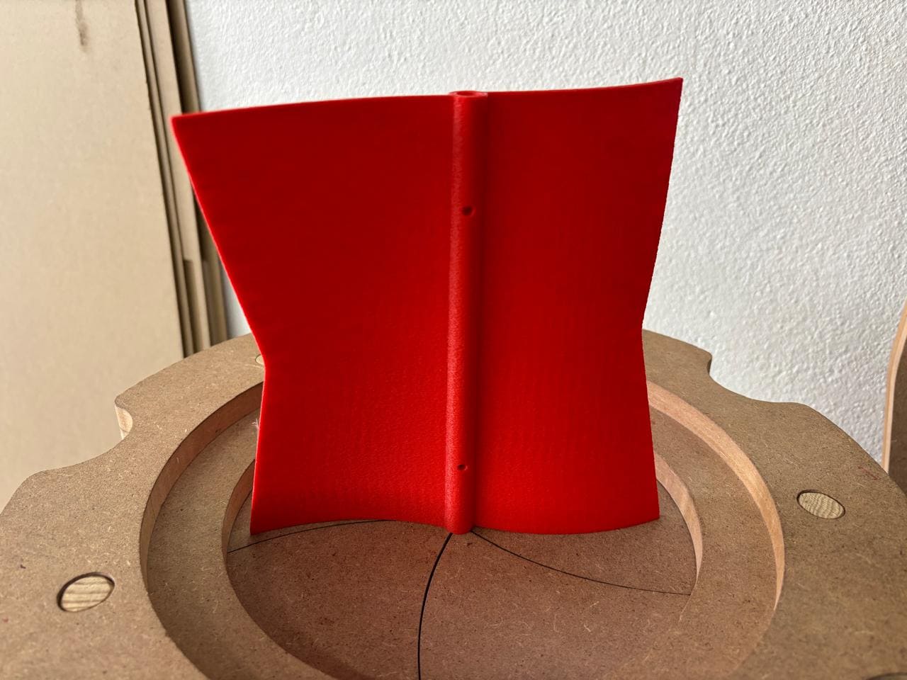
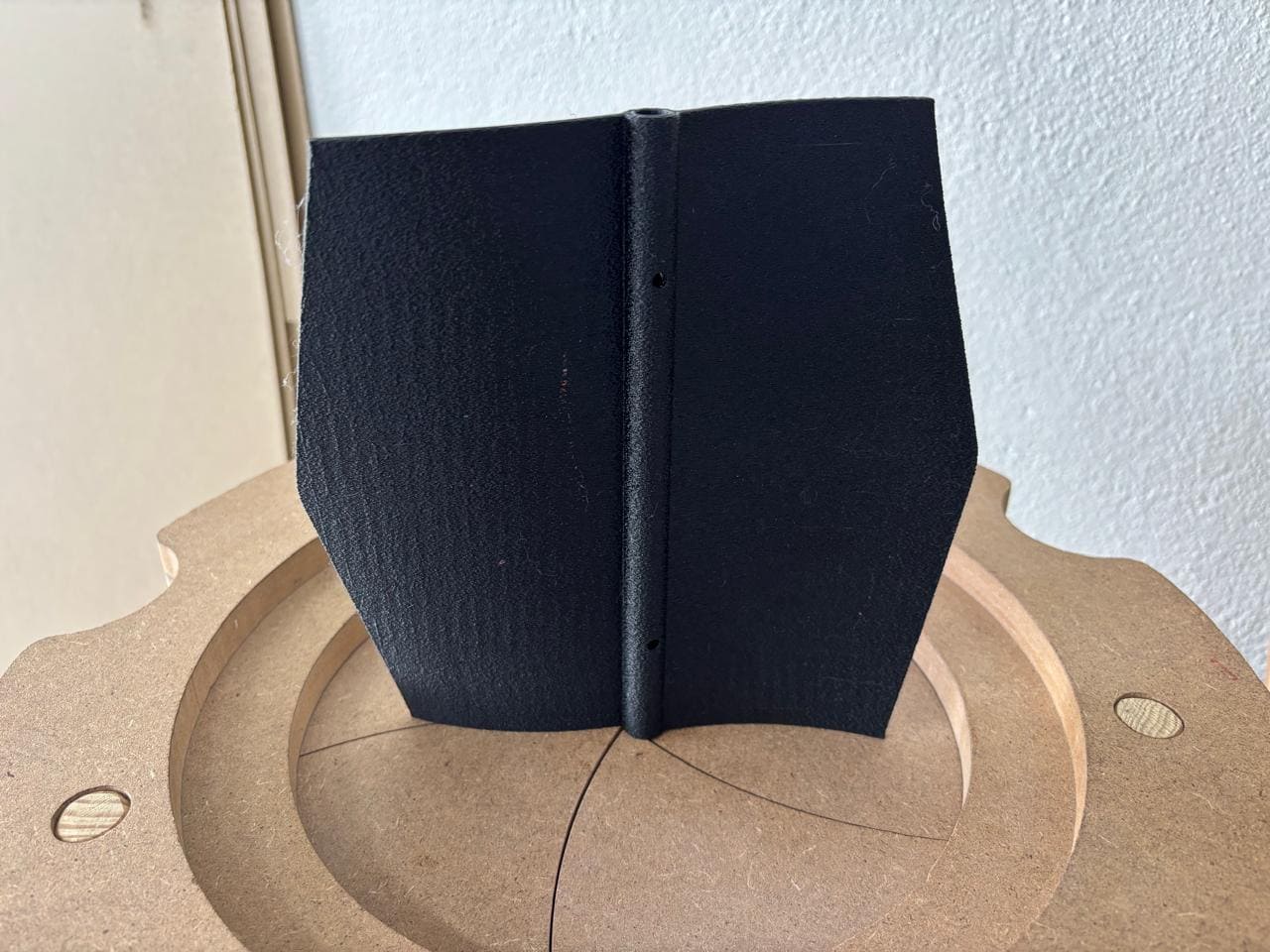
This image shows the selected blade in a front view, highlighting four key dimensions that explain its modular design. The blade has a total height of 45 cm, with two differentiated parts in terms of maximum width to prevent collisions during rotation. The first blade section has a width of 4.5 cm at the base and a maximum of 8 cm at the top, while the second section reaches a width of 10 cm at its widest point. This staggered design allows both blades to complement each other when rotating, maximizing wind capture without interfering with each other.
Total height
45 cm
Width of the first blade
8cm
Width of the second blade
4.5 cm
Segmented design to prevent collisions and improve wind capture
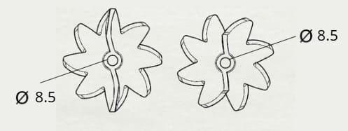
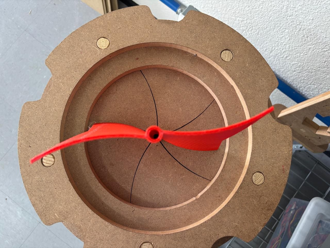
The second image presents a top view of the blade design, showing a central diameter of 8.5 mm. This diameter is where an aluminum tube will be inserted, on which the blades will be mounted to form a complete structure. This modularity in design addresses the limitations of the 3D printer, which cannot print such a large piece in a single go. The assembled structure allows for building a larger blade by mounting each segment on the tube, providing stability and facilitating prototype maintenance.
Central diameter
8.5 mm for aluminum tube insertion
Modular structure to facilitate 3D printing and assembly
3D Printing Parameters and Settings
To achieve optimal performance and high quality in the propeller models, specific 3D printing settings were chosen. These parameters were carefully adjusted based on the propeller shape, material properties, and desired durability.
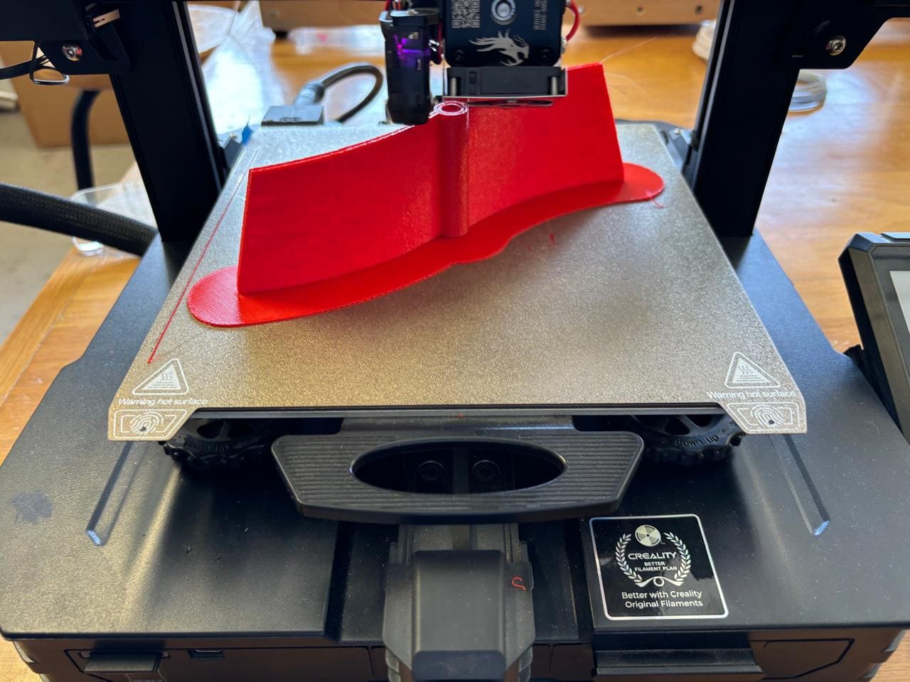
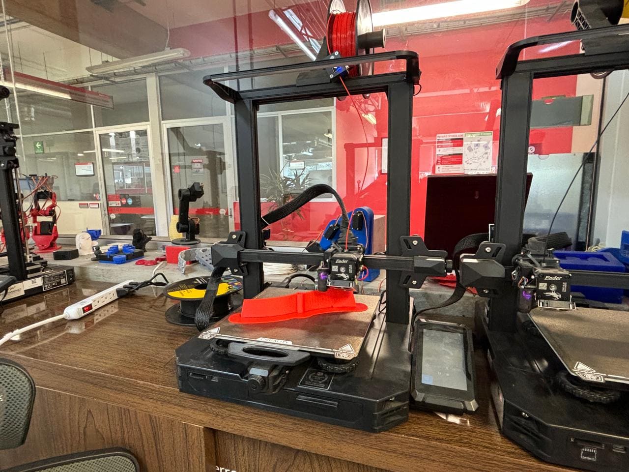
Printer Used: Ender-3 S1 Pro
The Ender-3 S1 Pro is a 3D printer that stands out for its excellent print quality and its ability to work with a wide range of materials. It is capable of printing in materials from PLA to more specialized materials such as TPU and PA.
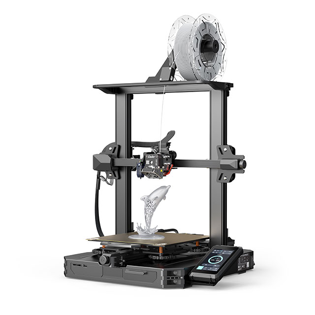
Some characteristics of the printer:
Printing Technology
FDM
Build Volume
220 x 220 x 270 mm
Printing Speed
150 mm/s
XY Resolution
± 0.1 mm
Layer Height
0.05 - 0.4 mm
Nozzle Temperature
Up to 300° C
Supported Materials
PLA, ABS, PETG, TPU, PA, WOOD
Print Settings for PLA
- Material: PLA was chosen for its ease of use and mechanical properties suitable for prototypes.
- Layer Height: A layer height of 0.2 mm was used to balance print time and surface finish, providing a smooth surface for better aerodynamics.
- Infill Density: 20% infill was applied to offer structural support without adding excessive weight.
- Print Orientation: The propellers were printed in a vertical position to ensure that the layer lines aligned with the stress direction, enhancing strength in critical areas.
- Print Speed: Set to 60 mm/s to reduce print time while maintaining quality.
- Supports: Minimal supports were used at the base of the propellers to ensure stability during printing. These were removed post-printing to achieve a clean finish.
- Nozzle Temperature: 200°C, optimal for PLA on the Ender-3 S1 Pro to ensure good layer adhesion without causing overheating issues.
- Bed Temperature: 60°C, providing optimal bed adhesion for PLA and preventing warping.
These parameters were determined after running multiple test prints, ensuring the best balance between print quality, strength, and material use.
Printing Process and Challenges
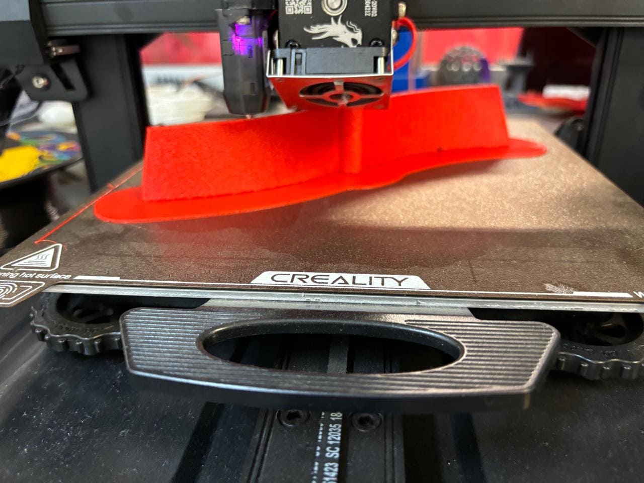
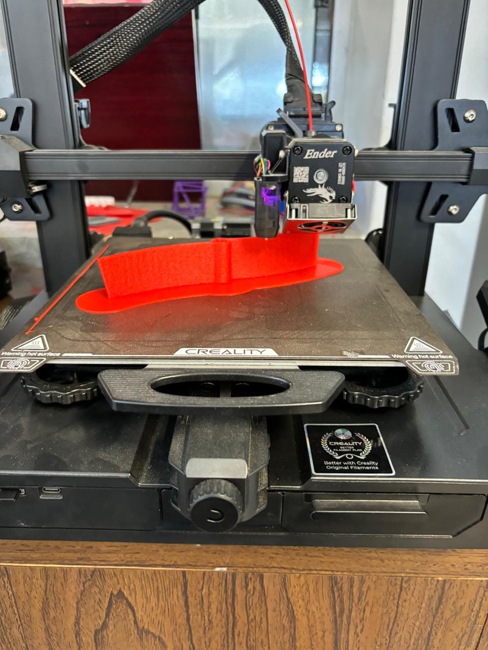
The propeller printing process presented various challenges, especially due to their size and complex shape. Below are some of the main issues encountered and the solutions implemented:
1. Warping
Given the large surface area of the propellers, warping was a concern during printing. To counteract this, a bed temperature of 60°C and a brim around the model were used to improve bed adhesion and prevent curling at the edges.
2. Layer Shifting
Layer shifting occasionally occurred due to the height of the prints. To mitigate this, the print speed was reduced to 50 mm/s, and the printer was placed on a stable surface to prevent vibrations.
3. Support Removal
Removing supports from delicate areas was a challenge. Supports were added only where absolutely necessary, and fine tweezers were used to carefully remove any remaining structures without damaging the propellers.
Despite these challenges, adjustments to the printing process allowed for high-quality prints that maintained the structural integrity of the design.
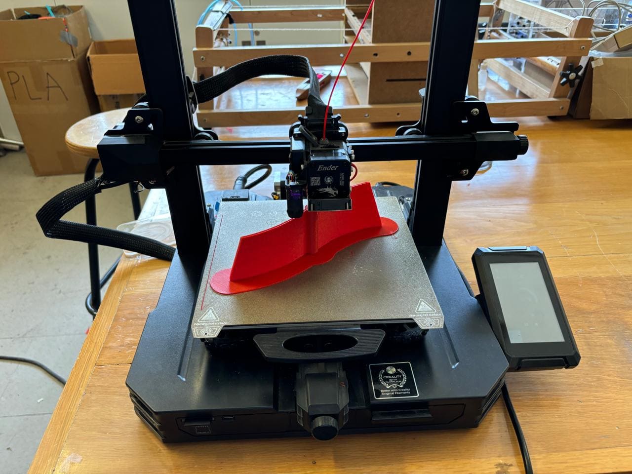
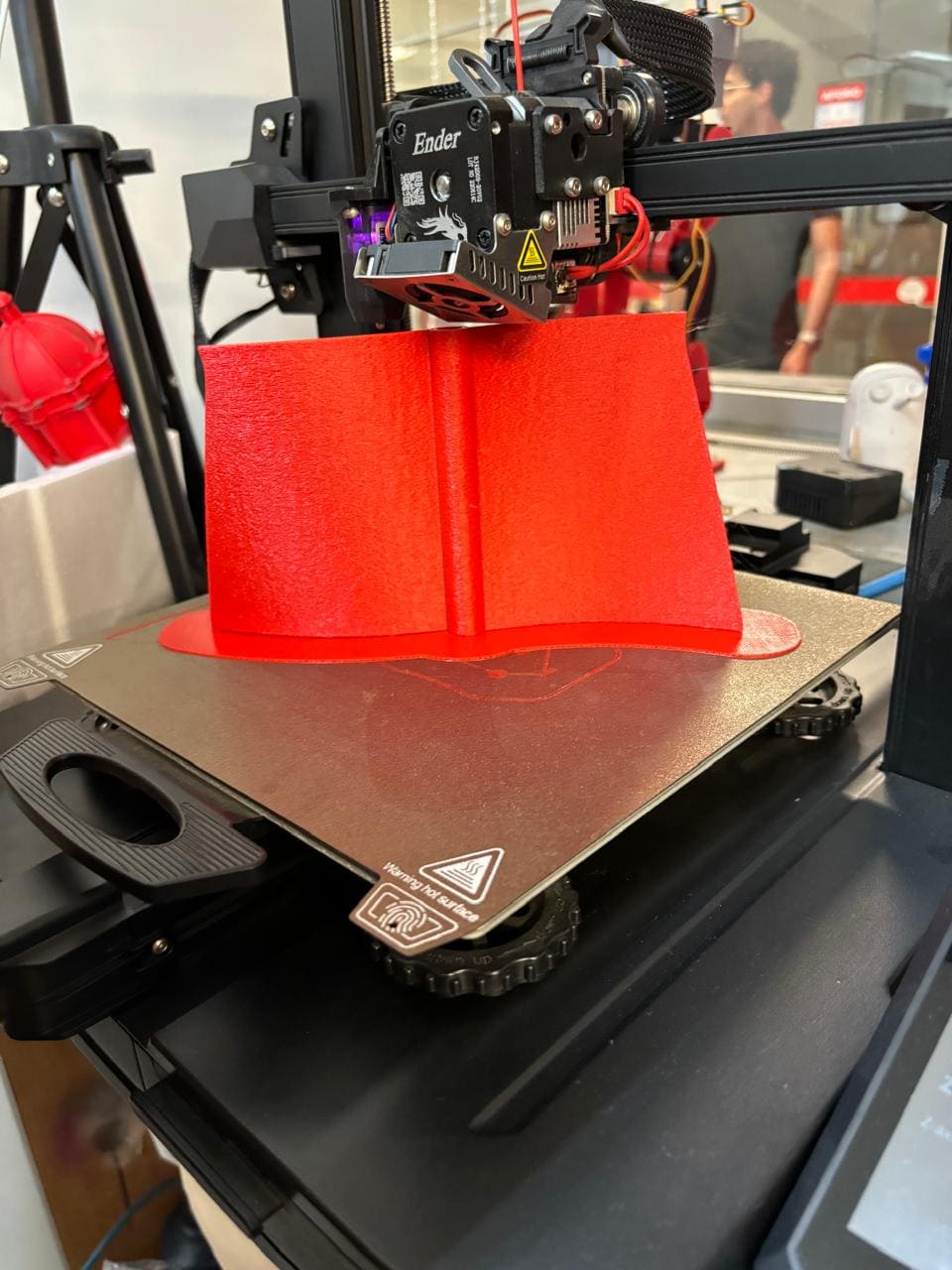
Final Quality Checks for Printed Parts
After printing, each propeller was subjected to a series of quality checks to ensure they met the required performance and durability standards.
1. Surface Finish
The propellers were inspected for rough surfaces or imperfections that could impact aerodynamic performance. Minor defects were sanded with fine-grit sandpaper to achieve a smooth surface.
2. Dimensional Accuracy
Calipers were used to measure critical dimensions of the propellers, such as width and height, to ensure they matched the design specifications. Minor adjustments were made to subsequent prints to improve accuracy where necessary.
3. Structural Integrity
Each propeller was manually tested for flexibility and resilience by applying light pressure. This test ensured that the propeller could withstand rotational forces without breaking or deforming.
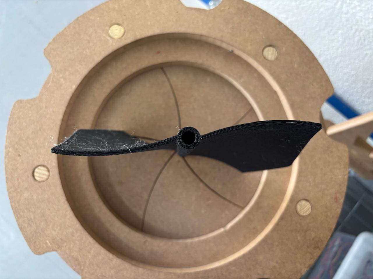
4. Fit Test
Finally, the propellers were mounted on the aluminum rod to confirm proper fit and alignment. This step ensured that the propellers would rotate smoothly and remain stable under operational conditions.
Once all checks were completed, the propellers were deemed ready for assembly and further testing in the prototype.
