Final Project: Photo-Podoscope
What does it do?
A photo-podoscope is a tool for assessing a footprint; it is performed by observing the supporting areas of the foot in standing position analyzed through image processing techniques. This evaluation and diagnosis generally is made by a specialist like a physiotherapist. Generally, this evaluation is made based on the form of the footprint by using a traditional podoscope or rudimentary process which carries several disadvantages[1].
This project intends to develop an affordable photo-podoscope with that can make healthcare accesible everywhere.
Who’s done what beforehand?
Previous work in the field includes various podoscopes and foot scanning devices. However, these are often costly and not accessible to all communities. The Photo-Podoscope aims to offer a low-cost alternative that is easy to replicate and improves accessibility to advanced foot care diagnostics.
What did you design?
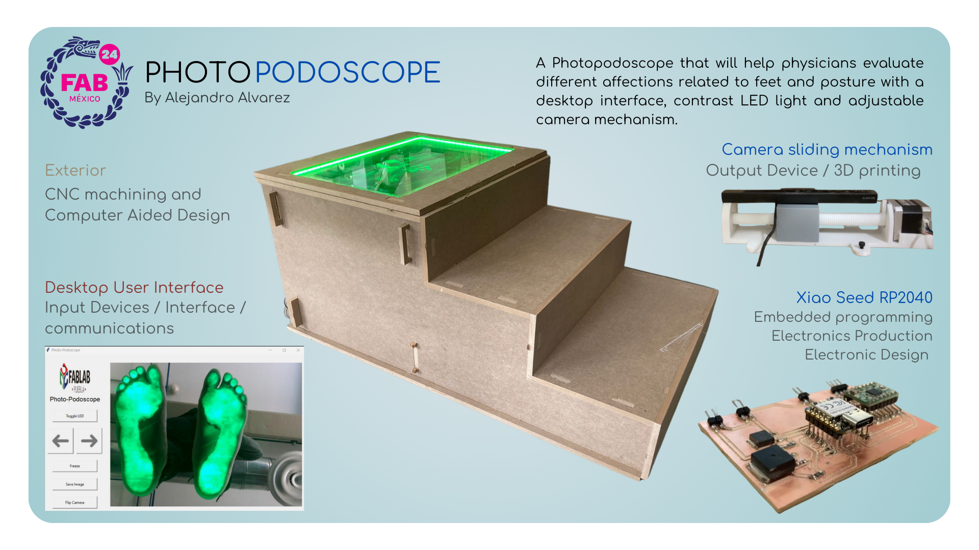
I designed the entire system from scratch, including:
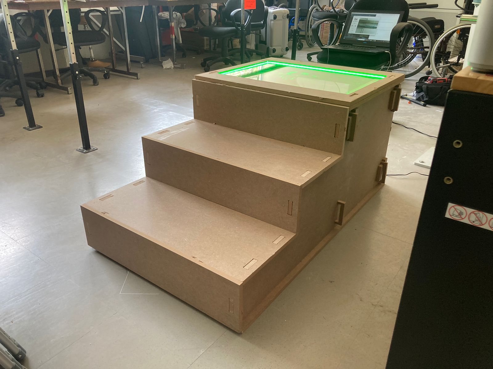
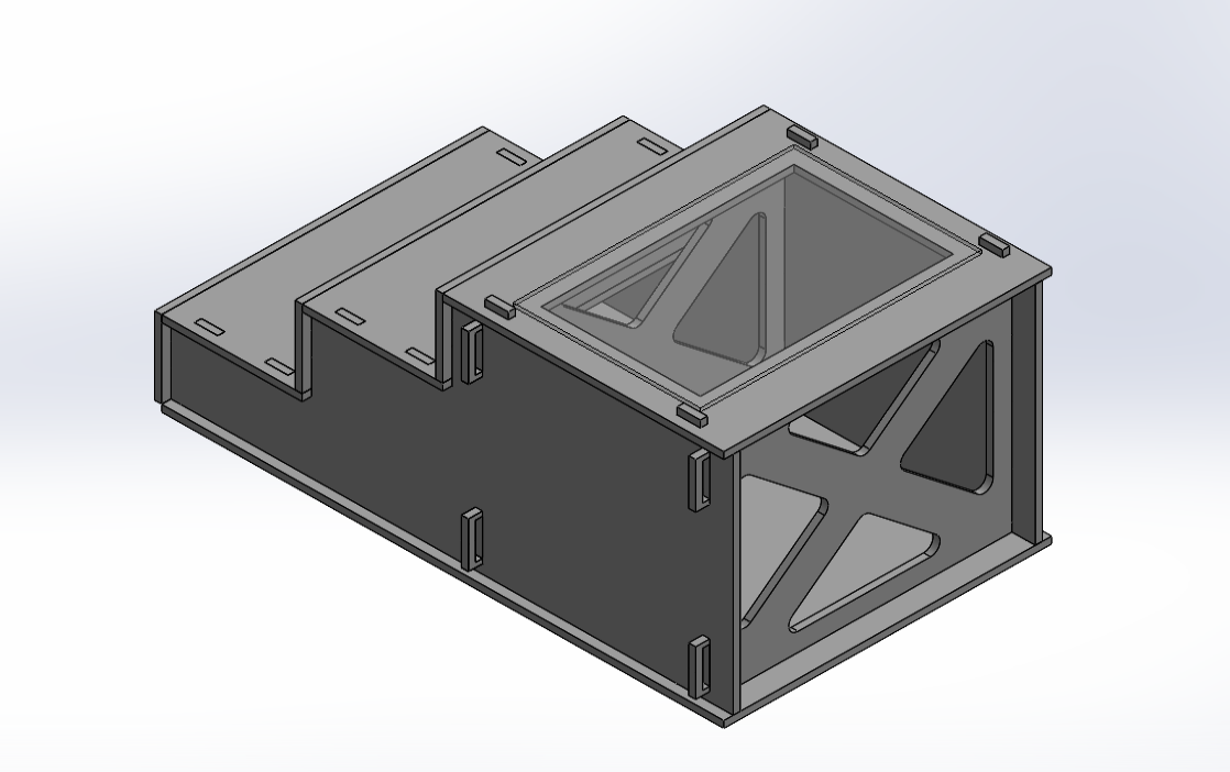
- A physical structure resembling steps with an acrylic platform for patients to stand on, made from MDF with CNC machining
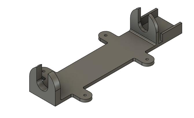
- A mechanism using a lead screw and nut system powered by a NEMA 17 stepper motor to move the camera laterally made with 3D printing in PETG
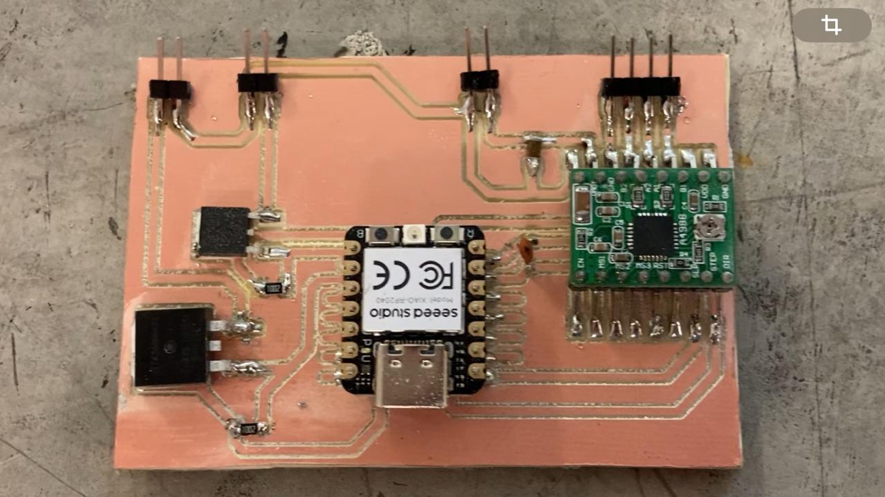
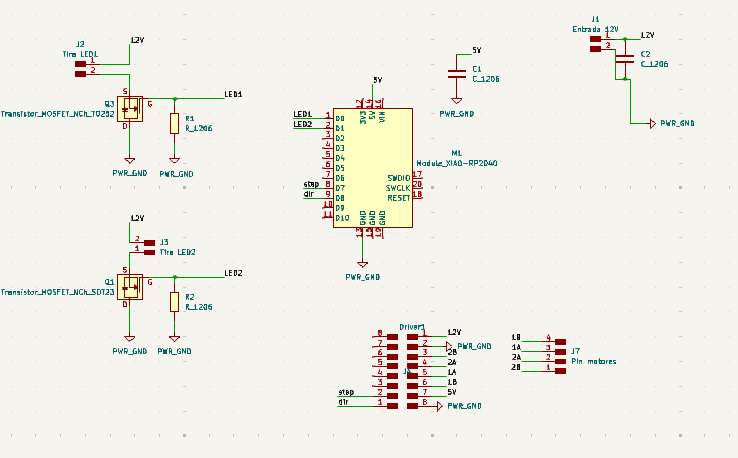
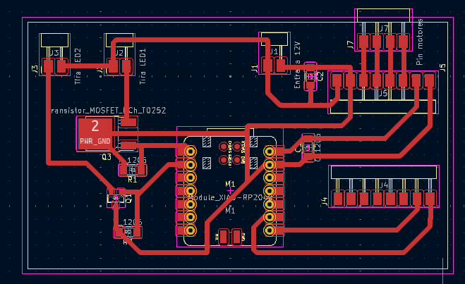
- A custom PCB integrating a Xiao Seed RP2040 microcontroller to control the LEDs and the motor.
- A software interface in Python using Tkinter for controlling the camera movement and lighting.
What materials and components were used?
| Component | Qty | Approximate Cost (USD) | Link/Where will they come from |
|---|---|---|---|
| MDF (15 mm) | 2 sheets | 50 | Provided by IBERO Puebla FAB Lab |
| Acrylic sheet (8 mm x 600 mm x 400 m) | 1 sheet | 75 | Provided by IBERO Puebla FAB Lab |
| PLA filament | 1 spool | 25 | Provided by IBERO Puebla FAB Lab |
| PETG filament | 1 spool | 30 | Provided by IBERO Puebla FAB Lab |
| NEMA 17 stepper motor | 1 | 15 | Provided by IBERO Puebla FAB Lab |
| Xiao Seed RP2040 microcontroller | 1 | 10 | Provided by IBERO Puebla FAB Lab |
| 5m LED strip | 1 | 15 | JAMS Electronica |
| Mosfet | 2 | 3 | Provided by IBERO Puebla FAB Lab |
| PCB board | 1 | 5 | Provided by IBERO Puebla FAB Lab |
| CNC router service | 1 service | N/A | Provided by IBERO Puebla FAB Lab |
| 3D printing service | 1 service | N/A | Provided by IBERO Puebla FAB Lab |
What parts and systems were made?
Physical Structure: The 15 mm MDF structure and acrylic platform were designed in a stair like shape to make easier for patients to step up, using anthropometric measures of the Mexican population and assembled with different internal structures that will ensure the weight is well distributed to minimize stress on critical points. The acrylic is 8 mm thick and was previously calculated with the provider datasheet to ensure patient safety.
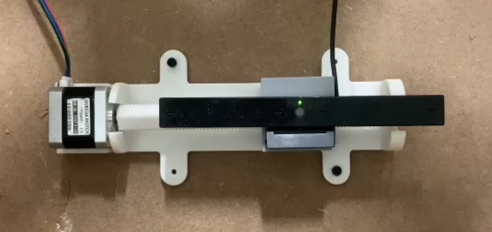
Camera Mechanism: The lateral movement mechanism for the camera was design with a Nut and screw system in mind. This type of mechanism allows to convert a rotational movement into a linear trajectory. This mechanism will be driven by a NEMA 17 motor and will have the webcam mounted on top of it. To create this mechanism, the most adequate form of prototyping is 3D printing. Although using a 3D printer for a screw can be challenging, It can be done by flattening a side of the screw and printing horizontal to maximize the strength
Custom PCB: The PCB was designed to integrate the microcontroller, motor driver A4988, and a LED strip. This PCB was design using KiCad and had a 12V input for both the Nema17 motor and the LED Strip. To ensure the correct flow of current a 1mm trace was calculated and the LED was turned On and Off by using a N type Mosfet transistor. The PCB was milled using the Roland SRM-20 and the XiaoSeed can be programmed using Arduino IDE.
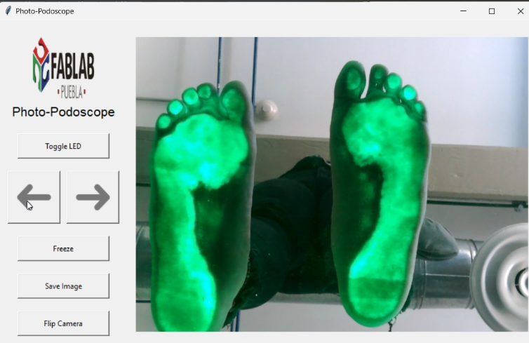
Software Interface: To control the camera and lighting, I developed a custom software interface. This interface, built with Python Tkinter, allows the health professional to precisely adjust the camera's position and lighting levels directly from their computer. The interface communicates with the Xiao Seed RP2040 microcontroller, which in turn controls the NEMA 17 stepper motor and the LED lighting. This setup ensures that the user can capture clear and detailed images of the patient's feet with ease.
What processes were used?
- CAD Design: SolidWorks was used for the MDF structure and Fusion 360 for the camera mechanism.
- PCB Design: KiCAD was utilized for designing the custom PCB.
- Fabrication:
- CNC Routing: The MDF structure was cut using a CNC router.
- 3D Printing: The camera mechanism parts were printed using PLA and PETG materials.
- PCB Milling: The custom PCB was fabricated using a Roland SRM-20 milling machine.
- Programming: Arduino IDE was used for programming the microcontroller in C#, and Python Tkinter was used to create the software interface.
What questions were answered?
- Can a low-cost podoscope be designed and built?
- How can a stepper motor and microcontroller be integrated to provide precise camera movement?
- How can the system be controlled via a user-friendly software interface?
What worked? What didn’t?
- Worked: The mechanical design, camera movement mechanism, PCB functionality, and software interface all worked as intended.
- Didn’t Work: Initial programming of the interface and tolerance issues in the 3D printed lead screw system required adjustments.
How was it evaluated?
- Finite Element Analysis (FEA): To ensure the structure's stability under load.
- Functional Testing: Testing the camera movement and lighting control.
- Usability Testing: Ensuring the software interface was user-friendly and effective.

Final Outcome:
Licensing
MIT License (Software)
The MIT License is a permissive free software license originating at the Massachusetts Institute of Technology (MIT). It allows for reuse within proprietary software provided that all copies of the licensed software include a copy of the MIT License terms. This license is simple and flexible, suitable for most projects involving software.
CERN OHL-S (Hardware)
The CERN Open Hardware License (OHL) is a license used for hardware designs. The OHL-S (Strongly Reciprocal) version ensures that any modifications to the hardware design must also be released under the same license, promoting open-source principles in hardware development.
